1994 JEEP CHEROKEE glove box
[x] Cancel search: glove boxPage 1703 of 1784
HEATER CORE AND HOUSING
REMOVAL
WARNING: HOT ENGINE COOLANT CAN CAUSE
SEVERE BURNS. DO NOT OPEN THE RADIATOR
DRAIN COCK WHEN THE COOLING SYSTEM IS
HOT AND PRESSURIZED. ALLOW THE COOLANT
TO DECREASE TO ROOM TEMPERATURE BEFORE
STARTING REPAIR OPERATIONS.
(1) Drain approximately 1.9 liters (2 qts) of coolant
from the radiator. Drain the coolant into a clean con-
tainer.
(2) Disconnect the heater hoses.
(3) Disconnect the vent door cables.
(4) Disconnect the blower motor wire.
(5) Disconnect the defroster duct.
(6) Remove the nuts that attach the heater hous-
ing studs to the engine compartment side of the dash
panel.
(7) Remove the heater housing assembly by tilting
it downward, to disengage it from the defroster duct.
Pull it rearward and out from under the instrument
panel.
(8) Remove the heater hosing cover from the hous-
ing.
(9) Remove the heater core from the housing.
INSTALLATION
(1) Install the heater core in the housing and in-
stall the cover on the housing.
(2) Position the heater housing on the dash panel.
Be sure the housing studs all extend through the
dash panel.
(3) Install the seals on the heater core outlet and
inlet tubes and over the blower motor housing.
(4) Install the attaching nuts on the housing studs.
CAUTION: DO NOT over tighten the attaching nuts.
The housing could become distorted causing air
leaks and improper heater door operation. Tighten
the nuts alternately and evenly until 2 stud threads
are visible beyond each nut.
(5) Connect the defroster duct to the housing.
(6) Connect the blower motor wire.
(7) Connect the vent door control cables.
(8) Connect the heater hoses.
(9) Fill and bleed the cooling system.
(10) Check system operation.
BLOWER MOTOR (HEATING)
REMOVAL
(1) Remove the heater housing.
(2) Remove the blower motor-to-heater housing at-
taching screws/nuts.
(3) Remove the blower motor from the housing.
INSTALLATION
(1) Position the blower motor into the housing.
(2) Install and tighten the blower motor-to-heater
housing attaching screws/nuts.
(3) Install the heater housing.
(4) Check blower motor and heater operation.
DEFROSTER NOZZLE AND DUCT
REMOVAL
WARNING: HOT ENGINE COOLANT CAN CAUSE
SEVERE BURNS. DO NOT OPEN THE RADIATOR
DRAIN COCK WHEN THE COOLING SYSTEM IS
HOT AND PRESSURIZED. ALLOW THE COOLANT
TO DECREASE TO ROOM TEMPERATURE BEFORE
STARTING REPAIR OPERATIONS.
(1) Drain approximately 1.9 liters (2 qts) of coolant
from the radiator. Drain the coolant into a clean con-
tainer.
(2) Disconnect the heater hoses.
(3) Remove the nuts attaching the heater housing
studs to the engine compartment side of the dash
panel.
(4) Disconnect the speedometer cable.
(5) Remove the glove box.
(6) Tilt the heater housing back and pull it rear-
ward and out from under the instrument panel.
(7) Disconnect the vent control cables.
(8) Remove the fresh air intake grille from the
cowl.
(9) Remove the fresh air intake duct.
(10) Lower the windshield.
(11) Remove the defroster nozzle attaching screws
and remove the nozzle and duct.
INSTALLATION
(1) Install the defroster nozzle and duct.
(2) Raise and secure the windshield.
(3) Install the fresh air intake duct.
(4) Install the fresh air intake grille on the cowl.
(5) Install the vent cables.
(6) Position the heater housing on the dash panel.
Be sure all the housing studs extend through the
dash panel.
(7) Install the seals on the blower motor and the
heater core inlet and outlet tubes.
(8) Install the attaching nuts on the housing studs.
CAUTION: DO NOT over tighten the attaching nuts.
The housing could become distorted causing air
leaks and improper heater door operation. Tighten
the nuts alternately and evenly until 2 stud threads
are visible beyond each nut.
(9) Install the glove box.
(10) Connect the speedometer cable.
(11) Connect the heater hoses.
24 - 40 HEATING AND AIR CONDITIONINGJ
Page 1704 of 1784
(12) Fill and bleed the cooling system.
FRESH AIR DOOR VACUUM MOTOR
REMOVAL
(1) Remove the glove box and assist handle.
(2) Disconnect the vacuum hose from the motor.
(3) Remove the motor lever retaining clip.
(4) Remove the motor attaching nuts and remove
the motor from the fresh air duct.
INSTALLATION
(1) Position the motor on the fresh air duct and in-
stall the motor attaching nuts.
(2) Align the motor lever with the air door lever
and install the lever retaining clip.
(3) Connect the vacuum hose to the motor.
(4) Install the glove box and assist handle.
FRESH AIR INTAKE DUCT
REMOVAL
WARNING: HOT ENGINE COOLANT CAN CAUSE
SEVERE BURNS. DO NOT OPEN THE RADIATOR
DRAIN COCK WHEN THE COOLING SYSTEM IS
HOT AND PRESSURIZED. ALLOW THE COOLANT
TO DECREASE TO ROOM TEMPERATURE BEFORE
STARTING REPAIR OPERATIONS.
(1) Drain approximately 1.9 liters (2 qts) of coolant
from the radiator. Drain the coolant into a clean con-
tainer.
(2) Disconnect the heater hoses.
(3) Remove the nuts attaching the heater housing
studs to the dash panel from inside the engine com-
partment.
(4) Disconnect the speedometer cable.
(5) Remove the glove box and assist handle.
(6) Tilt the heater housing back and pull it rear-
ward and out from under the instrument panel.
(7) Disconnect the vent cables.
(8) Remove the fresh air intake grille from the
cowl.
(9) Remove the fresh air intake duct.
INSTALLATION
(1) Install the fresh air intake duct.
(2) Install the defroster nozzle and duct.
(3) Raise and secure the windshield.
(4) Install the fresh air grille on the cowl.
(5) Install the vent cables.
(6) Position the heater housing on the dash panel.
Be sure all the housing studs extend through the
dash panel.
(7) Install the seals on the blower motor and
heater core inlet and outlet tubes.
(8) Install the attaching nuts on the heater hous-
ing studs.CAUTION: DO NOT over tighten the attaching nuts.
The housing could become distorted causing air
leaks and improper heater door operation. Tighten
the nuts alternately and evenly until 2 stud threads
are visible beyond each nut.
(9) Install the glove box and assist handle.
(10) Connect the speedometer cable.
(11) Connect the heater hoses.
(12) Fill and bleed the cooling system.
DESCRIPTION (AIR CONDITIONING)
The evaporator, blower fan and motor, thermostat,
expansion valve, capillary tube, air outlets and sys-
tem controls are located in the evaporator housing.
The evaporator housing is mounted under the instru-
ment panel. The compressor, condenser, receiver-
dryer and refrigerant lines are located in the engine
compartment.
A rotary-type compressor with magnetic clutch op-
erated drive pulley is used for all vehicles equipped
with air conditioning.
SIGHT GLASS
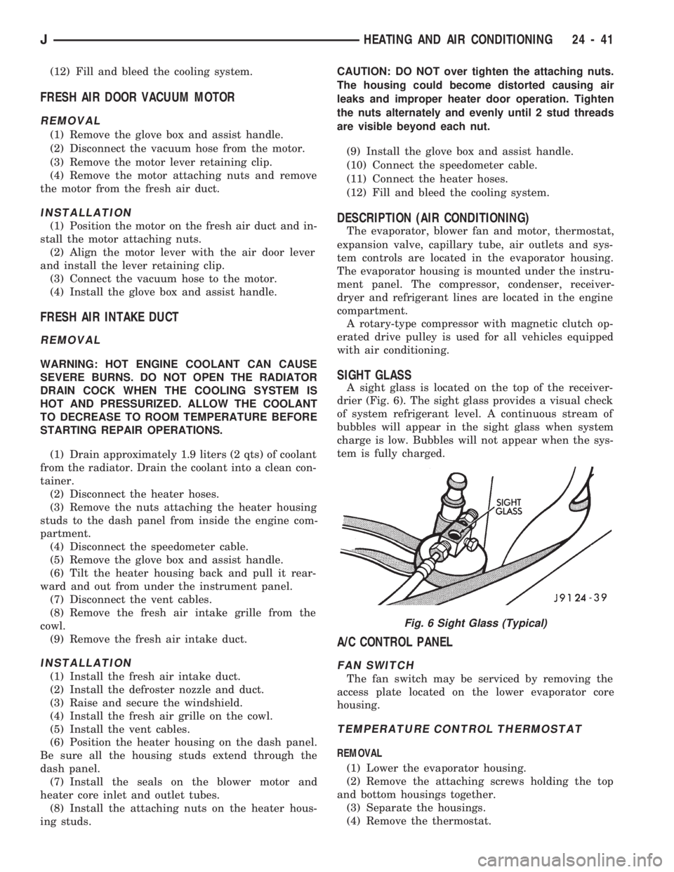
A sight glass is located on the top of the receiver-
drier (Fig. 6). The sight glass provides a visual check
of system refrigerant level. A continuous stream of
bubbles will appear in the sight glass when system
charge is low. Bubbles will not appear when the sys-
tem is fully charged.
A/C CONTROL PANEL
FAN SWITCH
The fan switch may be serviced by removing the
access plate located on the lower evaporator core
housing.
TEMPERATURE CONTROL THERMOSTAT
REMOVAL
(1) Lower the evaporator housing.
(2) Remove the attaching screws holding the top
and bottom housings together.
(3) Separate the housings.
(4) Remove the thermostat.
Fig. 6 Sight Glass (Typical)
JHEATING AND AIR CONDITIONING 24 - 41
Page 1737 of 1784
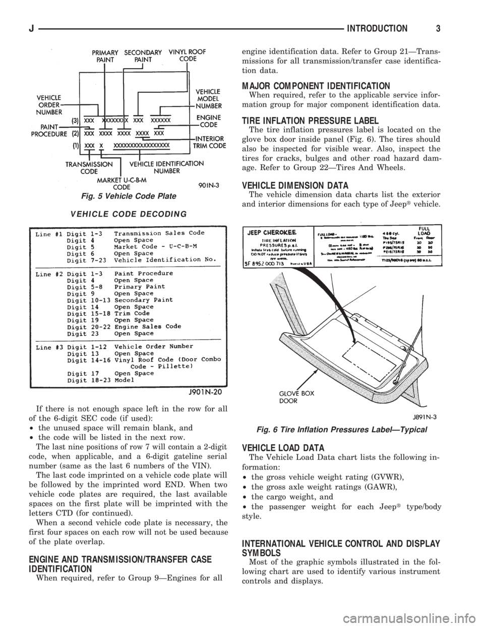
If there is not enough space left in the row for all
of the 6-digit SEC code (if used):
²the unused space will remain blank, and
²the code will be listed in the next row.
The last nine positions of row 7 will contain a 2-digit
code, when applicable, and a 6-digit gateline serial
number (same as the last 6 numbers of the VIN).
The last code imprinted on a vehicle code plate will
be followed by the imprinted word END. When two
vehicle code plates are required, the last available
spaces on the first plate will be imprinted with the
letters CTD (for continued).
When a second vehicle code plate is necessary, the
first four spaces on each row will not be used because
of the plate overlap.
ENGINE AND TRANSMISSION/TRANSFER CASE
IDENTIFICATION
When required, refer to Group 9ÐEngines for allengine identification data. Refer to Group 21ÐTrans-
missions for all transmission/transfer case identifica-
tion data.
MAJOR COMPONENT IDENTIFICATION
When required, refer to the applicable service infor-
mation group for major component identification data.
TIRE INFLATION PRESSURE LABEL
The tire inflation pressures label is located on the
glove box door inside panel (Fig. 6). The tires should
also be inspected for visible wear. Also, inspect the
tires for cracks, bulges and other road hazard dam-
age. Refer to Group 22ÐTires And Wheels.
VEHICLE DIMENSION DATA
The vehicle dimension data charts list the exterior
and interior dimensions for each type of Jeeptvehicle.
VEHICLE LOAD DATA
The Vehicle Load Data chart lists the following in-
formation:
²the gross vehicle weight rating (GVWR),
²the gross axle weight ratings (GAWR),
²the cargo weight, and
²the passenger weight for each Jeepttype/body
style.
INTERNATIONAL VEHICLE CONTROL AND DISPLAY
SYMBOLS
Most of the graphic symbols illustrated in the fol-
lowing chart are used to identify various instrument
controls and displays.
Fig. 5 Vehicle Code Plate
VEHICLE CODE DECODING
Fig. 6 Tire Inflation Pressures LabelÐTypical
JINTRODUCTION3
Page 1747 of 1784
BODY SOLENOIDS, TRANSMISSION
VALVE ............................21-175
BODY STRIPES/DECALS...........23-25,23-153
BODY, THROTTLE.................14-29,14-59
BODY UNDERCOAT....................23-203
BOOSTER CHECK VALVE TEST, POWER......5-11
BOOSTER INSTALLATION, POWER
BRAKE..........................5-23,5-51
BOOSTER OPERATION, POWER BRAKE......5-22
BOOSTER, POWER BRAKE............5-22,5-40
BOOSTER REMOVAL, POWER BRAKE . . . 5-22,5-51
BOOSTER TEST, MASTER CYLINDER/
POWER.............................5-11
BOOSTER VACUUM TEST, POWER..........5-12
BORES, HONING CYLINDER................9-2
BOX, GLOVE.........................23-194
BRACKET, FUEL FILTER.................23-86
BRACKET, FUEL FILTER SHIELD...........13-17
BRACKET, I/P TWEETER SPEAKER/
COURTESY LAMP SUPPORT............23-95
BRACKET, MUFFLER/TAILPIPE HANGER.....13-16
BRACKET, REARVIEW MIRROR
RETAINING........................23-183
BRACKET REPLACEMENT, INTERIOR
REARVIEW MIRROR SUPPORT..........23-75
BRACKETS, CATALYTIC CONVERTER/
MUFFLER/TAILPIPE SUPPORT...........23-85
BRACKETSÐXJ VEHICLES, SPARE TIRE/
WHEEL HOLDDOWN AND FLOOR.......23-128
BRAKE ADJUSTMENT, DRUM..............5-35
BRAKE ADJUSTMENT PARKING............5-63
BRAKE BLEEDINGÐBRAKE FLUID AND
LEVELÐBRAKELINES AND HOSES........5-13
BRAKE BLEEDINGÐWITH ABS BRAKES.....5-14
BRAKE BLEEDINGÐWITH STANDARD
BRAKES.............................5-13
BRAKE BOOSTER INSTALLATION,
POWER.........................5-23,5-51
BRAKE BOOSTER OPERATION, POWER......5-22
BRAKE BOOSTER, POWER............5-22,5-40
BRAKE BOOSTER REMOVAL, POWER . . . 5-22,5-51
BRAKE CABLE TENSIONER REPLACEMENT
(XJ), PARKING........................5-61
BRAKE CHECK, PRELIMINARY..............5-7
BRAKE COMPONENTS, WHEEL.............5-1
BRAKE DIAGNOSIS, ABS..................5-3
BRAKE DIAGNOSIS, SERVICE..............5-7
BRAKE DRUM REFINISHING..............5-37
BRAKE FLUID CONTAMINATION............5-13
BRAKE FLUID, IMPORTANCE OF CLEAN.....5-48
BRAKE FLUID LEVEL....................5-13
BRAKE FLUID, RECOMMENDED........5-13,5-48
BRAKE FLUID TUBE RETAINER CLIP,
FUEL AND; BODY COMPONENTSÐXJ
VEHICLES..........................23-86
BRAKE FLUID TUBE RETAINER CLIP,
FUEL AND; FRAME AND BUMPERS......13-16
BRAKE FLUID/LUBRICANTS/CLEANING
SOLVENTS............................5-1
BRAKE FRONT CABLE REPLACEMENT
(YJ), PARKING........................5-62
BRAKE INDICATOR INOPERATIVE..........8E-4
BRAKE INDICATOR LAMP; INSTRUMENT
PANEL AND GAUGESÐXJ...............8E-2
BRAKE INDICATOR LAMP; INSTRUMENT
PANEL AND GAUGESÐYJ
..............8E-16
BRAKE LEVER INSTALLATION (XJ WITH
FULLCONSOLE), PARKING
..............5-60
BRAKE LEVER INSTALLATION (XJ WITH
MINICONSOLE), PARKING
...............5-58
BRAKE LEVER INSTALLATION (XJ
WITHOUT CONSOLE), PARKING
..........5-60
BRAKE LEVER REMOVAL (XJ WITH FULL
CONSOLE), PARKING
..................5-59
BRAKE LEVER REMOVAL (XJ WITH MINI
CONSOLE), PARKING
..................5-58
BRAKE LEVER REMOVAL (XJ WITHOUT
CONSOLE), PARKING
..................5-60
BRAKE OPERATION, PARKING
.............5-56
BRAKE OVERHAUL, SECOND
............21-232
BRAKE PACK REQUIREMENTS, AW-4
CLUTCH
...........................21-328
BRAKE PEDAL AND BRAKELIGHT
SWITCH
.............................5-65
BRAKE PEDAL INSTALLATION
.............5-66BRAKE PEDAL INSTALLATION (YJ),
PARKING............................5-61
BRAKE PEDAL REMOVAL.................5-65
BRAKE PEDAL REMOVAL (YJ), PARKING....5-61
BRAKE PEDAL SERVICE..................5-65
BRAKE PISTON AND TRANSMISSION
CASE OVERHAUL, FIRST-REVERSE......21-237
BRAKE PROBLEMS, DIAGNOSING
PARKING............................5-10
BRAKE PROBLEMS, DIAGNOSING
SERVICE.............................5-8
BRAKE REAR CABLE REPLACEMENT
(XJ), PARKING........................5-62
BRAKE REAR CABLE REPLACEMENT (YJ),
PARKING............................5-63
BRAKE ROTOR REFINISHING, DISC.........5-32
BRAKE ROTOR RUNOUT, DISC............5-31
BRAKE ROTOR THICKNESS, DISC..........5-31
BRAKE ROTOR THICKNESS VARIATION,
DISC...............................5-31
BRAKE SAFETY PRECAUTIONS.............5-2
BRAKE SERVO, SECOND COAST.........21-181
BRAKE SWITCH.......................14-54
BRAKE SWITCHÐPCM INPUT............14-20
BRAKE SYSTEM (ABS), ANTILOCK..........5-1
BRAKE SYSTEM (ABS) INDICATOR
LAMP, ANTI-LOCK.....................8E-2
BRAKE SYSTEM OPERATION, ANTILOCK.....5-43
BRAKE SYSTEM, POWER.................0-32
BRAKE TORQUE SPECIFICATIONS..........5-67
BRAKE WARNING LIGHT DISPLAY...........5-4
BRAKE WARNING LIGHTS.................5-1
BRAKELIGHT SWITCH ADJUSTMENT........5-66
BRAKELIGHT SWITCH, BRAKE PEDAL.......5-65
BRAKELIGHT SWITCH INSTALLATION.......5-66
BRAKELIGHT SWITCH REMOVAL...........5-66
BRAKELINE CHARTS....................5-15
BRAKELINES AND HOSES................5-15
BRAKELINING MATERIAL..................5-1
BRAKES, BRAKE BLEEDINGÐWITH ABS.....5-14
BRAKES, BRAKE BLEEDINGÐWITH
STANDARD..........................5-13
BRAKES, DISC.........................5-24
BRAKES, DRUM........................5-34
BRAKES, PARKING......................5-56
BRAKES, POWER........................5-1
BRAKESHOE INSTALLATION, DISC..........5-26
BRAKESHOE INSTALLATION, DRUM........5-34
BRAKESHOE REMOVAL, DISC.............5-25
BRAKESHOE REMOVAL, DRUM............5-34
BRAKING MODE, ABS OPERATION IN
ANTILOCK...........................5-43
BRAKING MODE, ABS OPERATION
IN NORMAL..........................5-43
BREAK-IN, ENGINE......................0-13
BRUSH GUARD........................23-3
BUCKET SEAT COMPONENTS, POWER....23-106
BUCKET SEAT CUSHION AND COVER......23-98
BUCKET SEAT PLATFORM AND TRACKS . . . 23-105
BUCKET SEATBACK COVER AND FRAME . . . 23-100
BUCKET SEATBACK RECONDITIONING.....23-102
BUCKET SEATS, FRONT.................23-97
BUFFING AND POLISHING..............23-203
BULB REPLACEMENT, BACK-UP/REAR
TURN SIGNAL/TAIL LAMP...............8L-9
BULB REPLACEMENT, FRONT PARK/
TURN SIGNAL LAMP
...................8L-8
BULB REPLACEMENT, HEADLAMP
..........8L-3
BULB REPLACEMENT, INSTRUMENT
CLUSTER
...........................8E-19
BULB REPLACEMENT, SIDE MARKER
LAMP
...............................8L-7
BULB REPLACEMENT, UNDERHOOD
LAMP
..............................8L-18
BULB REPLACEMENTÐYJ VEHICLES,
HARDTOP DOME/CARGO LAMP
.........8L-20
BULB/ELEMENT REPLACEMENT, FOG
LAMP
..............................8L-13
BUMPER, FRONT
..................13-3,13-14
BUMPER, LIFTGATE LICENSE PLATE
SCREW ANCHOR
.....................23-72
BUMPER, REAR
...................13-6,13-18
BUMPER, REAR JOUNCE
................13-18
BUMPERÐXJ VEHICLES, REAR
SEATBACK LATCH STRIKER
...........23-111BUMPERS AND FRAME ATTACHED
COMPONENTS, YJ....................13-14
BUMPERS, FUEL FILLER DOOR...........23-31
BUMPERS, XJ.........................13-3
BUSHING AND PISTON CLEARANCE, AW-
4 ................................21-326
BUSHING REPLACEMENT, AXLE.......2-11,2-32
BUSHING REPLACEMENT, LEAF SPRING
EYE; FRONT SUSPENSION AND AXLE.....2-15
BUSHING REPLACEMENT, LEAF SPRING
EYE; REAR SUSPENSION AND AXLES . . . 3-4,3-6
BUZZER SYSTEM, CHIME/WARNING........8A-1
CABLE, ACCELERATOR PEDAL AND
THROTTLE.....................14-16,14-54
CABLE ADJUSTMENT, PARK INTERLOCK . . . 21-186
CABLE ADJUSTMENT, SHIFT............21-186
CABLE ADJUSTMENT, TRANSMISSION
THROTTLE....................21-98,21-185
CABLE ADJUSTMENT, TRANSMISSION
THROTTLE VALVE....................21-70
CABLE ADJUSTMENT (XJ), PARK
INTERLOCK.........................21-97
CABLE ADJUSTMENT (XJ), SHIFT.........21-97
CABLE REPLACEMENT, HEATER
CONTROL..........................24-30
CABLE REPLACEMENT, LATCH
RELEASE...........................23-10
CABLE REPLACEMENT, SERVO............8H-9
CABLE REPLACEMENT, TRANSMISSION
THROTTLE.........................21-184
CABLE REPLACEMENT (XJ),
PARKING BRAKE REAR.................5-62
CABLE REPLACEMENT (YJ), PARKING
BRAKE FRONT........................5-62
CABLE REPLACEMENT (YJ), PARKING
BRAKE REAR.........................5-63
CABLE RESISTANCE, SPARK PLUG........8D-18
CABLE TENSIONER REPLACEMENT (XJ),
PARKING BRAKE......................5-61
CABLE, THROTTLE.....................14-16
CABLEÐCONSOLE SHIFT AUTOMATIC,
PARK-LOCK.........................19-45
CABLES, DISTRIBUTOR CAP AND ROTOR,
IGNITION............................0-18
CABLES, SPARK PLUG SECONDARY . . 8D-17,8D-29
CABLES, VENT DOOR CONTROL..........24-39
CALIBRATION VALUES, GAUGE...........8E-22
CALIPER ASSEMBLY....................5-29
CALIPER CLEANING AND INSPECTION......5-28
CALIPER DISASSEMBLY..................5-27
CALIPER INSTALLATION..................5-30
CALIPER OPERATION AND WEAR
COMPENSATION......................5-24
CALIPER REMOVAL.....................5-27
CAMSHAFT........................9-29,9-69
CAMSHAFT PIN REPLACEMENT........9-31,9-71
CAMSHAFT POSITION SENSOR; FUEL
SYSTEM............................14-54
CAMSHAFT POSITION SENSOR;
IGNITION SYSTEMS..............8D-1,8D-20
CAMSHAFT POSITION SENSORÐPCM
INPUT.............................14-20
CAMSHAFT POSITION SENSOR TEST;
FUEL SYSTEM.......................14-43
CAMSHAFT POSITION SENSOR TEST;
IGNITION SYSTEMS...................8D-8
CANADA ONLY, DAYTIME RUNNING
LIGHTS............................8L-16
CANISTER, EVAP...................25-4,25-9
CAP AND ROTOR, IGNITION CABLES,
DISTRIBUTOR........................0-18
CAP, DISTRIBUTOR.....................8D-9
CAP, FUEL TANK FILLER TUBE; EMISSION
CONTROL SYSTEMS...............25-4,25-9
CAP, FUEL TANK FILLER TUBE; FUEL
SYSTEM............................14-12
CAP, RADIATOR PRESSURE...............7-20
CAPACITIES, COOLING SYSTEM...........7-38
CAPACITIES, FLUID......................0-4
CAPACITIES, FUEL TANK...........14-12,14-62
CAPACITY TEST, FUEL PUMP..............14-7
CAR REPLACEMENT, PITMAN SHAFT
SEALSÐIN
.........................19-21
CARDAN (CV), DOUBLE
.................16-10
CARDAN, SINGLE
.......................16-9
CARDAN U-JOINT, AXLE SHAFT
............2-25
JINDEX3
Description Group-Page Description Group-Page Description Group-Page
Page 1754 of 1784
FUSES AND ABBREVIATIONS, SYMBOLS, . . . 8W-6
FUSIBLE LINK REPLACEMENT............8W-4
FUSIBLE LINKS........................8W-3
GALVANIZED METALS, PAINT REPAIR ON . . 23-202
GAP ADJUSTMENT, WHEEL SENSOR AIR....5-49
GAP, REAR SPEED SENSOR AIR............5-3
GASKET FAILURE DIAGNOSIS, ENGINE
CYLINDER HEAD.......................9-5
GASKETS, FORM-IN-PLACE................9-1
GAUGE AND MANIFOLD ASSEMBLY,
PRESSURE..........................24-2
GAUGE CALIBRATION VALUES............8E-22
GAUGE CLUSTER REPLACEMENT.........8E-24
GAUGE, COOLANT TEMPERATURE..........8E-1
GAUGE, FUEL..........................8E-2
GAUGE HOUSINGS, INSTRUMENT
CLUSTER..........................23-190
GAUGE INOPERATIVE, COOLANT
TEMPERATURE.......................8E-3
GAUGE INOPERATIVE, FUEL...............8E-3
GAUGE INOPERATIVE, OIL PRESSURE......8E-3
GAUGE INOPERATIVE, ONE..............8E-22
GAUGE, OIL PRESSURE..................8E-1
GAUGE PACKAGE DIAGNOSIS............8E-22
GAUGE PACKAGE GAUGE REPLACEMENT . . . 8E-24
GAUGE PACKAGE GENERAL
INFORMATION.......................8E-22
GAUGE PACKAGE SERVICE PROCEDURES . . . 8E-24
GAUGE REPLACEMENT, GAUGE
PACKAGE...........................8E-24
GAUGE REPLACEMENTÐINSTRUMENT
CLUSTER REMOVED...................8E-5
GAUGE SENDING UNIT, FUEL.............14-15
GAUGES AND INDICATORS INOPERATIVE....8E-3
GAUGES INOPERATIVE (FIG. 15), ALL......8E-22
GAUGES, INSTRUMENT CLUSTER;
INSTRUMENT PANEL AND GAUGESÐ
XJ ................................8E-13
GAUGES, INSTRUMENT CLUSTER;
INSTRUMENT PANEL AND GAUGESÐ
YJ ................................8E-27
GAUGES, INSTRUMENT PANEL......8A-1 ,8E-27
GAUGES, PRESSURE....................22-2
GAUGESÐXJ, INSTRUMENT PANEL........8E-1
GAUGESÐYJ, INSTRUMENT PANEL........8E-1
GEAR (1) POSITION, HYDRAULIC FLOW
IN MANUAL FIRST...................21-94
GEAR ADJUSTMENTS IN VEHICLE.........19-37
GEAR ADJUSTMENTS ON BENCH.........19-42
GEAR ADJUSTMENTS, STEERING.........19-22
GEAR AND BEARING NOISE; FRONT
SUSPENSION AND AXLE................2-16
GEAR AND BEARING NOISE; REAR
SUSPENSION AND AXLES................3-7
GEAR AND CLUTCH OVERHAUL,
OVERDRIVE PLANETARY..............21-209
GEAR AND NO. 1 ONE-WAY CLUTCH
OVERHAUL, SUN....................21-229
GEAR ASSEMBLY, STEERING.............19-41
GEAR ASSEMBLY/INSTALLATION,
PINION; FRONT SUSPENSION AND AXLE....2-40
GEAR ASSEMBLY/INSTALLATION,
PINION; REAR SUSPENSION AND AXLES....3-22
GEAR CLEANING AND INSPECTION........19-40
GEAR COMPONENTS, FIRSTÐTHIRDÐ
REVERSE..........................21-159
GEAR (CONVERTER CLUTCH
ENGAGED), HYDRAULIC FLOW IN
THIRD.............................21-90
GEAR DEPTH INFORMATION, PINION;
FRONT SUSPENSION AND AXLE..........2-37
GEAR DEPTH INFORMATION, PINION;
REAR SUSPENSION AND AXLES..........3-19
GEAR DEPTH VARIANCE, PINION; FRONT
SUSPENSION AND AXLE................2-38
GEAR DEPTH VARIANCE, PINION; REAR
SUSPENSION AND AXLES...........3-20,3-38
GEAR DISASSEMBLY INFORMATION.......19-24
GEAR, HYDRAULIC FLOW IN D RANGE
FIRST..............................21-87
GEAR, HYDRAULIC FLOW IN D RANGE
SECOND
............................21-88
GEAR, HYDRAULIC FLOW IN D
RANGE THIRD
.......................21-89
GEAR INSTALLATION, RING
...............3-24
GEAR LEAKAGE DIAGNOSIS
..............19-8GEAR, MANUAL STEERING.........19-35,19-73
GEAR OVERDRIVE COMPONENTS,
FOURTH...........................21-158
GEAR OVERHAUL, FRONT PLANETARY....21-228
GEAR OVERHAUL, GOVERNOR AND
PARK .............................21-121
GEAR, POWER STEERING...............19-73
GEAR RATIOS..........................21-2
GEAR RATIOS, TRANSMISSION...........21-33
GEAR, RECIRCULATING BALL POWER
STEERING..........................19-19
GEAR REPLACEMENT, STEERING....19-21,19-43
GEAR SELECTOR INDICATOR
REPLACEMENTÐINSTRUMENT
CLUSTER REMOVED...................8E-6
GEAR SERVICE, GOVERNOR AND PARK . . . 21-101
GEAR SPECIFICATIONS, MANUAL
STEERING..........................19-44
GEAR SPECIFICATIONS, POWER
STEERING..........................19-34
GEAR, SPEED SENSOR ROTORÐ
SPEEDOMETER DRIVE...............21-183
GEAR TRAIN OVERHAUL, PLANETARY.....21-131
GEARÐYJ VEHICLES, MANUAL
STEERING...........................0-32
GEARS, RECIRCULATING-BALL
POWER STEERING...................19-69
GEARSHIFT LINKAGE...................21-70
GEARSHIFT LINKAGE ADJUSTMENT (YJ) . . . 21-96
GEARTRAIN OPERATION AND
APPLICATION CHARTS...............21-159
GENERAL; BATTERY/STARTER/
GENERATOR SERVICE..................8B-7
GENERAL BODY SERVICE INFORMATION....23-1
GENERAL; CHIME/BUZZER WARNING
SYSTEMS...........................8U-1
GENERAL DIAGNOSIS INFORMATION;
CLUTCH..............................6-3
GENERAL DIAGNOSIS INFORMATION;
TRANSMISSION AND TRANSFER
CASE.............................21-167
GENERAL; HEATING AND AIR
CONDITIONING.......................24-8
GENERAL INFORMATION, 2.5L STARTER....8B-4
GENERAL INFORMATION, 4.0L STARTER....8B-6
GENERAL INFORMATION; AUDIO
SYSTEMS........................8F-1,8F-8
GENERAL INFORMATION, BATTERY
TESTING............................8A-3
GENERAL INFORMATION; BATTERY/
STARTER/GENERATOR SERVICE......8B-1,8B-4
GENERAL INFORMATION; BRAKES . . . 5-1,5-7,5-24,
5-39,5-65
GENERAL INFORMATION; CLUTCH..........6-1
GENERAL INFORMATION; COOLING
SYSTEM.................7-1,7-31,7-37,7-38
GENERAL INFORMATION; ELECTRICAL . 8A-1,8A-2,
8A-8,8A-9,8A-14
GENERAL INFORMATION; EMISSION
CONTROL SYSTEMS...................25-1
GENERAL INFORMATION; ENGINES......9-9,9-50
GENERAL INFORMATION; EXHAUST
SYSTEM AND INTAKE MANIFOLD.........11-1
GENERAL INFORMATION; FRAME AND
BUMPERS.......................13-1,13-8
GENERAL INFORMATION; FRONT
SUSPENSION AND AXLE..........2-1,2-5,2-16
GENERAL INFORMATION, FRONT WIPERS/
WASHERS...........................8K-8
GENERAL INFORMATION; FUEL SYSTEM....14-1,
14-12,14-16,14-17,14-32,14-62
GENERAL INFORMATION, GAUGE
PACKAGE...........................8E-22
GENERAL INFORMATION; HEATING
AND AIR CONDITIONING................24-1
GENERAL INFORMATION; HORNS..........8G-1
GENERAL INFORMATION; IGNITION
SYSTEMS
.......8D-1,8D-8,8D-20,8D-30,8D-33
GENERAL INFORMATION, INSTRUMENT
CLUSTER; INSTRUMENT PANEL
AND GAUGESÐXJ
....................8E-1
GENERAL INFORMATION, INSTRUMENT
CLUSTER; INSTRUMENT PANEL AND
GAUGESÐYJ
........................8E-14
GENERAL INFORMATION; LUBRICATION
AND MAINTENANCE
....................0-1GENERAL INFORMATION; PROPELLER
SHAFTS.............................16-1
GENERAL INFORMATION; REAR
SUSPENSION AND AXLES........3-1,3-7,3-11
GENERAL INFORMATION; STEERING........19-1
GENERAL INFORMATION; TRANSMISSION
AND TRANSFER CASE.......21-1,21-32,21-66,
21-69,21-156,21-272,21-293
GENERAL INFORMATION; VEHICLE
SPEED CONTROL SYSTEM..............8H-1
GENERAL INFORMATION; WHEELS AND
TIRES..........................22-1,22-6
GENERAL INFORMATION; WIRING
DIAGRAMS..........................8W-1
GENERAL; POWER DOOR LOCKS..........8P-1
GENERAL; POWER MIRRORS.............8T-1
GENERAL; POWER SEATS................8R-1
GENERAL; REAR WINDOW DEFOGGER......8N-1
GENERAL SERVICE INFORMATION; BODY
COMPONENTSÐXJ VEHICLES.........23-132
GENERAL SERVICE INFORMATION;
BRAKES.........................5-20,5-56
GENERAL SERVICE MAINTENANCE..........0-5
GENERAL SERVICE PROCEDURE
INFORMATION.......................19-69
GENERAL SERVICE, STEERING COLUMN . . . 19-45
GENERAL SPECIFICATIONS, 30RH/32RH . . . 21-322
GENERAL SPECIFICATIONS, AW-4........21-324
GENERATOR DIAGNOSTIC TROUBLE
CODE (DTC)........................8A-19
GENERATOR FIELDÐPCM OUTPUT........14-25
GENERATOR LAMPÐPCM OUTPUT........14-25
GENERATOR REPLACEMENTÐLEFT
HAND DRIVE.........................8B-7
GENERATOR REPLACEMENTÐ
RIGHT HAND DRIVE...................8B-9
GENERATOR SERVICE PROCEDURES.......8B-7
GENERATOR SPECIFICATIONS............8B-12
GENERATOR SPLASH SHIELD............13-14
GENERATOR TEST PROCEDURES ON
VEHICLE...........................8A-14
GLASS AND DOOR OPENING WEATHERSTRIP
SEALS, DOOR WINDOW...............23-62
GLASS, FIXEDÐWATER LEAK
DETECTION AND REPAIR........23-83,23-189
GLASS, FIXED WINDOW..........23-73,23-183
GLASS, FRONT DOOR WINDOW..........23-49
GLASS, FULL-METAL DOOR VENT
WINDOW..........................23-177
GLASS, FULL-METAL DOOR WINDOW.....23-178
GLASS, HARD TOP LIFTGATE............23-162
GLASS, HARD TOP QUARTER WINDOW . . . 23-188
GLASS, REAR DOOR FIXED WINDOW......23-53
GLASS, REAR DOOR WINDOW
...........23-52
GLASS REGULATOR, FRONT DOOR
WINDOW
...........................23-48
GLASS REGULATOR, FULL-METAL
DOOR WINDOW
....................23-177
GLASS REGULATOR HANDLE, FULL-
METAL DOOR WINDOW
..............23-175
GLASS REGULATOR, REAR DOOR
WINDOW
...........................23-51
GLASS REPLACEMENT, WINDSHIELD
......23-75
GLASS, SIGHT
........................24-41
GLASS WEATHERSTRIP SEAL
REPLACEMENT, LIFTGATE
.............23-163
GLASS, WINDSHIELD
..................23-185
GLASSÐXJ VEHICLES, LIFTGATE
WINDOW
...........................23-81
GLASSÐXJ VEHICLES, REAR
QUARTER VENT WINDOW
..............23-80
GLASS/REAR QUARTER PLASTIC INSERT
ÐXJ VEHICLES, QUARTER WINDOW
.....23-80
GLOVE BOX
.........................23-194
GOVERNOR AND PARK GEAR
OVERHAUL
........................21-121
GOVERNOR AND PARK GEAR SERVICE
....21-101
GRID REPAIR, REAR WINDOW
DEFOGGER
..........................8N-2
GRID TEST, REAR WINDOW DEFOGGER
.....8N-1
GRILLE AND GRILLE OPENING PANEL
(GOP)
..............................23-3
GRILLE AND SCREEN, COWL
.......23-11,23-139
GRILLE APPLIQUE, RADIATOR
...........23-134
10 INDEXJ
Description Group-Page Description Group-Page Description Group-Page