1994 JEEP CHEROKEE glove box
[x] Cancel search: glove boxPage 765 of 1784
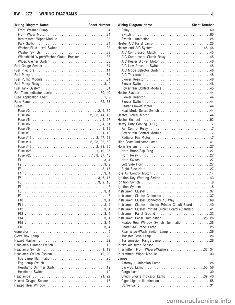
Wiring Diagram Name Sheet Number
Front Washer Pump.........................34
Front Wiper Motor..........................34
Intermittent Wiper Module.....................33
Park Switch..............................34
Washer Fluid Level Switch.....................33
Washer Switch............................33
Windshield Wiper/Washer Circuit Breaker...........33
Wiper/Washer Switch........................33
Fuel Gauge Sensor...........................54
Fuel Injectors...............................14
Fuel Pump.................................54
Fuel Pump Module...........................54
Fuel Pump Relay............................3,9
Fuel Tank System............................54
Full Time Indicator Lamp.....................39, 40
Fuse Application Chart........................1,2
Fuse Panel..............................62, 63
Fuses
Fuse #2.............................2,4,60
Fuse #4..........................2,33,44,46
Fuse #5.............................1,4,27
Fuse #6.............................1,4,51
Fuse #9...............................1,19
Fuse #10..............................1,19
Fuse #13............................2,47,58
Fuse #14.........................2,23,33,60
Fuse #19............................2,33,35
Fuse #25............................1,19,25
Fuse #26..........................1,8,37,43
F1 ...................................3,4
F2 ...................................3,9
F3 ...................................3,17
F4 ...................................3,4
F5 .................................3,6,17
F6 .................................3,9,10
F7 .....................................3
F8 ...................................3,4
F9 .....................................3
F10 ...................................3,4
F11 ...................................3,4
F12 ...................................3,4
F13 ...................................3,4
F14 ...................................3,4
F15 ...................................3,4
F16 ...................................3,4
Generator..................................5
Glove Box Lamp.............................29
Hazard Flasher..............................32
Headlamp Dimmer Switch.......................19
Headlamp Switch...........................1,19
Headlamp Switch System.....................19, 20
Fog Lamp Illumination........................20
Fog Lamp Switch...........................20
Headlamp Dimmer Switch.....................19
Headlamp Switch...........................19
Headlamps..............................21, 22
Heated Oxygen Sensor.........................13
Heated Rear Window..........................60Wiring Diagram Name Sheet Number
Relay...................................60
Switch..................................60
Switch Illumination..........................25
Heater A/C Panel Lamp........................25
Heater and A/C System......................45, 46
A/C Compressor Clutch.......................45
A/C Compressor Clutch Relay...................45
A/C Heater Blower Motor......................46
A/C Low Pressure Switch.....................45
A/C Mode Selector Switch.....................46
A/C Thermostat............................45
Blower Resistor............................46
Blower Switch.............................46
Powertrain Control Module.....................45
Heater System..............................44
Blower Resistor............................44
Blower Switch.............................44
Heater Blower Motor.........................44
Heat Mode Select Switch......................44
Heater Blower Motor..........................44
Heater Element..............................52
Heavy Duty Cooling (4.0L).......................7
Fan Control Relay...........................7
Powertrain Control Module.....................7
Radiator Fan Motor..........................7
High-Beam Indicator Lamp......................41
Horn System...............................27
Horn Brush/Slip Ring........................27
Horn Relay...............................27
Horn Switch..............................27
Left Side Horn.............................27
Right Side Horn............................27
Idle Air Control Motor.........................14
Ignition Key Warning Switch.....................43
Ignition Switch...............................8
Ignition System..............................8
Instrument Cluster............................37
Instrument Cluster Connector.....................37
Instrument Cluster Connector 16 Way...............69
Instrument Cluster Indicator Printed Circuit Board.......40
Instrument Cluster Printed Circuit Board (Standard)......41
Instrument Panel Ground.......................32
Instrument Panel Illumination..................25, 26
Heated Rear Window Switch Illumination...........25
Heater A/C Panel Lamp.......................25
Rear Wiper/Wash Switch Lamp..................26
Transfer Case Lamp.........................26
Transmission Range Lamp.....................26
Intake Air Temp Sensor........................11
Intermittent Front Wipers/Washers...............33, 34
Intermittent Wiper Module.......................33
Lamps
Ashtray Illumination Lamp.....................26
Back-Up Lamp..........................55, 56
Cargo Lamp..............................30
Check Engine Indicator Lamp................39, 40
Cigar Lighter Illumination......................58
Dome Lamp..............................31
8W - 272 WIRING DIAGRAMSJ
Page 766 of 1784
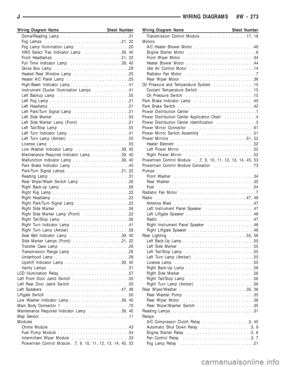
Wiring Diagram Name Sheet Number
Dome/Reading Lamp.........................31
Fog Lamps............................21, 22
Fog Lamp Illumination Lamp...................20
4WD Select Trac Indicator Lamp..............39, 40
Front Headlamps.........................21, 22
Full Time Indicator Lamp...................39, 40
Glove Box Lamp...........................29
Heated Rear Window Lamp....................25
Heater A/C Panel Lamp.......................25
High-Beam Indicator Lamp.....................41
Instrument Cluster Illumination Lamps.............41
Left Backup Lamp..........................55
Left Fog Lamp.............................21
Left Headlamp.............................21
Left Park/Turn Signal Lamp....................21
Left Side Marker...........................55
Left Side Marker Lamp (Front)..................21
Left Tail/Stop Lamp.........................55
Left Turn Indicator Lamp......................41
Left Turn Lamp (Amber)......................55
License Lamp.............................55
Low Washer Indicator Lamp.................39, 40
Maintenance Required Indicator Lamp...........39, 40
Malfunction Indicator Lamp..................39, 40
Park Brake Indicator Lamp.....................40
Park/Turn Signal Lamps....................21, 22
Reading Lamp.............................31
Rear Wiper/Wash Switch Lamp..................26
Right Back-up Lamp.........................56
Right Fog Lamp............................22
Right Headlamp............................22
Right Park/Turn Signal Lamp...................22
Right Side Marker..........................56
Right Side Marker Lamp (Front).................22
Right Tail/Stop Lamp........................56
Right Turn Indicator Lamp.....................41
Right Turn Lamp (Amber).....................56
Seat Belt Indicator Lamp...................39, 40
Side Marker Lamps (Front)..................21, 22
Transfer Case Lamp.........................26
Transmission Range Lamp.....................26
Underhood Lamp...........................28
Upshift Indicator Lamp.....................39, 40
Vanity Lamps.............................31
LCD Illumination Relay.........................57
Left Front Door Jamb Switch.....................50
Left Rear Door Jamb Switch.....................50
Left Speakers............................47, 48
Liftgate Switch..............................50
Low Washer Indicator Lamp...................39, 40
Main Body Connector 1........................70
Maintenance Required Indicator Lamp............39, 40
Map Sensor................................11
Modules
Chime Module.............................43
Fuel Pump Module..........................54
Intermittent Wiper Module.....................33
Powertrain Control Module . .7, 9, 10, 11, 12, 13, 14, 45, 53Wiring Diagram Name Sheet Number
Transmission Control Module.................17, 18
Motors
A/C Heater Blower Motor......................46
Engine Starter Motor.........................6
Front Wiper Motor..........................34
Heater Blower Motor.........................44
Idle Air Control Motor........................14
Radiator Fan Motor..........................7
Rear Wiper Motor..........................36
Oil Pressure and Temperature System...............15
Coolant Temperature Switch....................15
Oil Pressure Switch.........................15
Park Brake Indicator Lamp......................40
Park Brake Switch............................42
Power Distribution Center........................1
Power Distribution Center Application Chart............4
Power Distribution Center Identification...............3
Power Mirror Connector........................61
Power Mirror Switch Assembly...................51
Power Mirrors............................51, 52
Heater Element............................52
Left Power Mirror..........................52
Right Power Mirror.........................52
Powertrain Control Module . . .7, 9, 10, 11, 12, 13, 14, 45, 53
Powertrain Control Module Connector...............73
Pumps
Front Washer.............................34
Rear Washer..............................35
Fuel...................................54
Radiator Fan Motor............................7
Radio.................................47, 48
Antenna Mast.............................47
Left Instrument Panel Speaker..................47
Left Liftgate Speaker.........................48
Radio..................................47
Right Instrument Panel Speaker.................48
Right Liftgate Speaker........................48
Rear Lighting............................55, 56
Left Back-Up Lamp..........................55
Left Side Marker...........................55
Left Tail/Stop Lamp.........................55
Left Turn Lamp (Amber)......................55
License Lamp.............................55
Right Back-Up Lamp.........................56
Right Side Marker..........................56
Right Tail/Stop Lamp........................56
Right Turn Lamp (Amber).....................56
Rear Wiper/Washer.........................35, 36
Rear Washer Pump.........................35
Rear Wiper Motor..........................36
Rear Wiper/Washer Switch.....................35
Reading Lamps..............................31
Relays
A/C Compressor Clutch Relay.................3,45
Automatic Shut Down Relay...................3,9
Engine Starter Relay........................3,6
Fan Control Relay.........................3,7
Fog Lamp Relay...........................21
JWIRING DIAGRAMS 8W - 273
Page 1457 of 1784
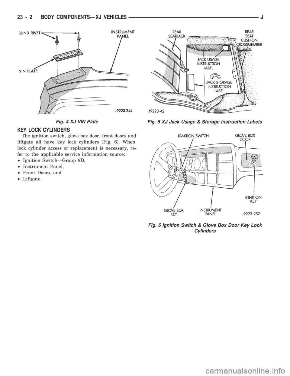
KEY LOCK CYLINDERS
The ignition switch, glove box door, front doors and
liftgate all have key lock cylinders (Fig. 6). When
lock cylinder access or replacement is necessary, re-
fer to the applicable service information source:
²Ignition SwitchÐGroup 8D,
²Instrument Panel,
²Front Doors, and
²Liftgate.
Fig. 4 XJ VIN PlateFig. 5 XJ Jack Usage & Storage Instruction Labels
Fig. 6 Ignition Switch & Glove Box Door Key Lock
Cylinders
23 - 2 BODY COMPONENTSÐXJ VEHICLESJ
Page 1587 of 1784
BODY COMPONENTSÐYJ VEHICLES
CONTENTS
page page
ADD-A-TRUNK........................ 198
DOORS.............................. 172
EXTERIOR COMPONENTS............... 134FIXED WINDOW GLASS................ 181
GENERAL SERVICE INFORMATION........ 132
INTERIOR COMPONENTS............... 188
GENERAL SERVICE INFORMATION
LABELS/DECALS/PLATES
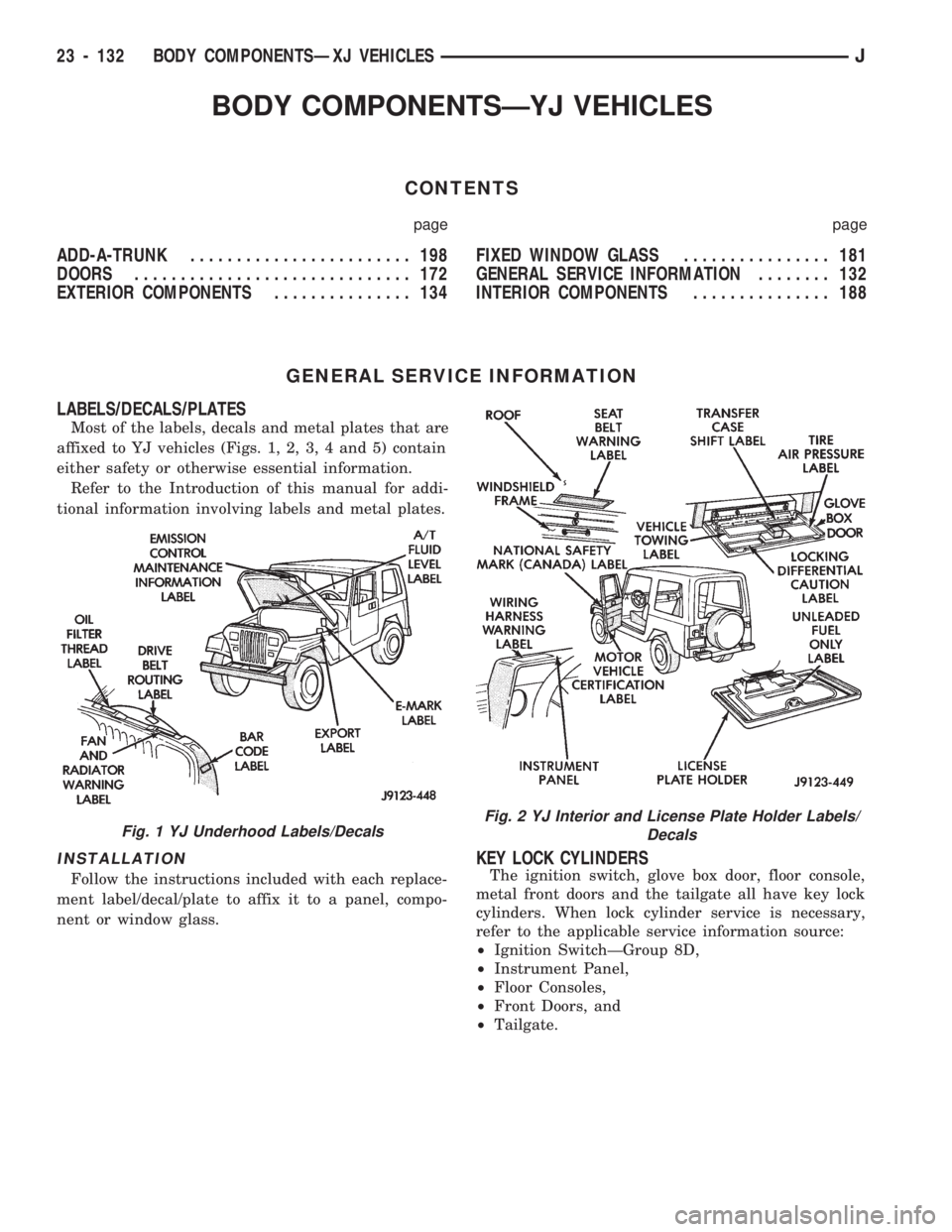
Most of the labels, decals and metal plates that are
affixed to YJ vehicles (Figs. 1, 2, 3, 4 and 5) contain
either safety or otherwise essential information.
Refer to the Introduction of this manual for addi-
tional information involving labels and metal plates.
INSTALLATION
Follow the instructions included with each replace-
ment label/decal/plate to affix it to a panel, compo-
nent or window glass.
KEY LOCK CYLINDERS
The ignition switch, glove box door, floor console,
metal front doors and the tailgate all have key lock
cylinders. When lock cylinder service is necessary,
refer to the applicable service information source:
²Ignition SwitchÐGroup 8D,
²Instrument Panel,
²Floor Consoles,
²Front Doors, and
²Tailgate.
Fig. 1 YJ Underhood Labels/DecalsFig. 2 YJ Interior and License Plate Holder Labels/
Decals
23 - 132 BODY COMPONENTSÐXJ VEHICLESJ
Page 1645 of 1784
INTERIOR COMPONENTS
INDEX
page page
Carpet/Floor Mats....................... 198
Floor Consoles......................... 197
Front Shoulder Belts..................... 196
Glove Box............................. 194
Instrument Cluster and Gauge Housings...... 190
Instrument Cluster Bezel.................. 191Instrument Panel........................ 190
Instrument Panel Components.............. 191
Instrument Panel Service.................. 192
Rear Shoulder Belts..................... 196
Seats................................ 195
Sunvisors............................. 196
INSTRUMENT PANEL
SERVICE INFORMATION
The instrument panel is constructed of sheet metal
and is attached to cowl panel with screws. The in-
strument panel and defroster grille pad is attached
to the instrument panel with screws.
INSTRUMENT CLUSTER AND GAUGE HOUSINGS
REMOVAL
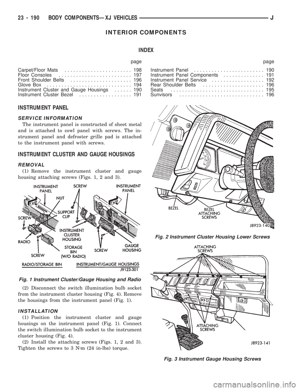
(1) Remove the instrument cluster and gauge
housing attaching screws (Figs. 1, 2 and 3).
(2) Disconnect the switch illumination bulb socket
from the instrument cluster housing (Fig. 4). Remove
the housings from the instrument panel (Fig. 1).
INSTALLATION
(1) Position the instrument cluster and gauge
housings on the instrument panel (Fig. 1). Connect
the switch illumination bulb socket to the instrument
cluster housing (Fig. 4).
(2) Install the attaching screws (Figs. 1, 2 and 3).
Tighten the screws to 3 Nzm (24 in-lbs) torque.
Fig. 2 Instrument Cluster Housing Lower Screws
Fig. 3 Instrument Gauge Housing Screws
Fig. 1 Instrument Cluster/Gauge Housing and Radio
23 - 190 BODY COMPONENTSÐXJ VEHICLESJ
Page 1648 of 1784
(4) Cover the hood surface area in front of the
windshield.
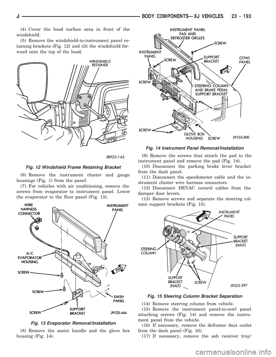
(5) Remove the windshield-to-instrument panel re-
taining brackets (Fig. 12) and tilt the windshield for-
ward onto the top of the hood.
(6) Remove the instrument cluster and gauge
housings (Fig. 1) from the panel.
(7) For vehicles with air conditioning, remove the
screws from evaporator to instrument panel. Lower
the evaporator to the floor panel (Fig. 13).
(8) Remove the assist handle and the glove box
housing (Fig. 14).(9) Remove the screws that attach the pad to the
instrument panel and remove the pad (Fig. 14).
(10) Disconnect the parking brake lever bracket
from the dash panel.
(11) Disconnect the speedometer cable and the in-
strument cluster wire harness connectors.
(12) Disconnect HEVAC control cables from the
damper door levers.
(13) Remove screws and separate the steering col-
umn support brackets (Fig. 15).
(14) Remove steering column from vehicle.
(15) Remove the instrument panel-to-cowl panel
attaching screws (Fig. 14) and remove the instru-
ment panel from the vehicle.
(16) If necessary, remove the defroster duct outlet
from the dash panel (Fig. 16).
(17) If necessary, remove the ash receiver tray/
Fig. 12 Windshield Frame Retaining Bracket
Fig. 13 Evaporator Removal/Installation
Fig. 14 Instrument Panel Removal/Installation
Fig. 15 Steering Column Bracket Separation
JBODY COMPONENTSÐXJ VEHICLES 23 - 193
Page 1649 of 1784
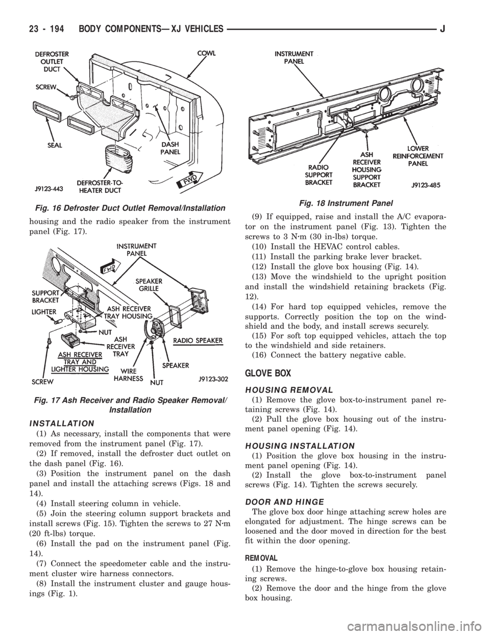
housing and the radio speaker from the instrument
panel (Fig. 17).
INSTALLATION
(1) As necessary, install the components that were
removed from the instrument panel (Fig. 17).
(2) If removed, install the defroster duct outlet on
the dash panel (Fig. 16).
(3) Position the instrument panel on the dash
panel and install the attaching screws (Figs. 18 and
14).
(4) Install steering column in vehicle.
(5) Join the steering column support brackets and
install screws (Fig. 15). Tighten the screws to 27 Nzm
(20 ft-lbs) torque.
(6) Install the pad on the instrument panel (Fig.
14).
(7) Connect the speedometer cable and the instru-
ment cluster wire harness connectors.
(8) Install the instrument cluster and gauge hous-
ings (Fig. 1).(9) If equipped, raise and install the A/C evapora-
tor on the instrument panel (Fig. 13). Tighten the
screws to 3 Nzm (30 in-lbs) torque.
(10) Install the HEVAC control cables.
(11) Install the parking brake lever bracket.
(12) Install the glove box housing (Fig. 14).
(13) Move the windshield to the upright position
and install the windshield retaining brackets (Fig.
12).
(14) For hard top equipped vehicles, remove the
supports. Correctly position the top on the wind-
shield and the body, and install screws securely.
(15) For soft top equipped vehicles, attach the top
to the windshield and side retainers.
(16) Connect the battery negative cable.
GLOVE BOX
HOUSING REMOVAL
(1) Remove the glove box-to-instrument panel re-
taining screws (Fig. 14).
(2) Pull the glove box housing out of the instru-
ment panel opening (Fig. 14).
HOUSING INSTALLATION
(1) Position the glove box housing in the instru-
ment panel opening (Fig. 14).
(2) Install the glove box-to-instrument panel
screws (Fig. 14). Tighten the screws securely.
DOOR AND HINGE
The glove box door hinge attaching screw holes are
elongated for adjustment. The hinge screws can be
loosened and the door moved in direction for the best
fit within the door opening.
REMOVAL
(1) Remove the hinge-to-glove box housing retain-
ing screws.
(2) Remove the door and the hinge from the glove
box housing.
Fig. 16 Defroster Duct Outlet Removal/Installation
Fig. 17 Ash Receiver and Radio Speaker Removal/
Installation
Fig. 18 Instrument Panel
23 - 194 BODY COMPONENTSÐXJ VEHICLESJ
Page 1650 of 1784
(3) If necessary, remove the retaining screws and
the hinge from the glove box door.
INSTALLATION
(1) If removed, install the hinge on the glove box
door with screws. Tighten the screws securely.
(2) Position the glove box door and hinge on the
glove box housing.
(3) Install the hinge-to-glove box housing screws
and adjust the door for proper fit within the opening.
Tighten the screws securely.
DOOR LATCH STRIKER ADJUSTMENT
The glove box door lock cylinder latch striker is at-
tached to the glove box housing opening with screws.
The striker can be moved in or out for adjustment.
SEATS
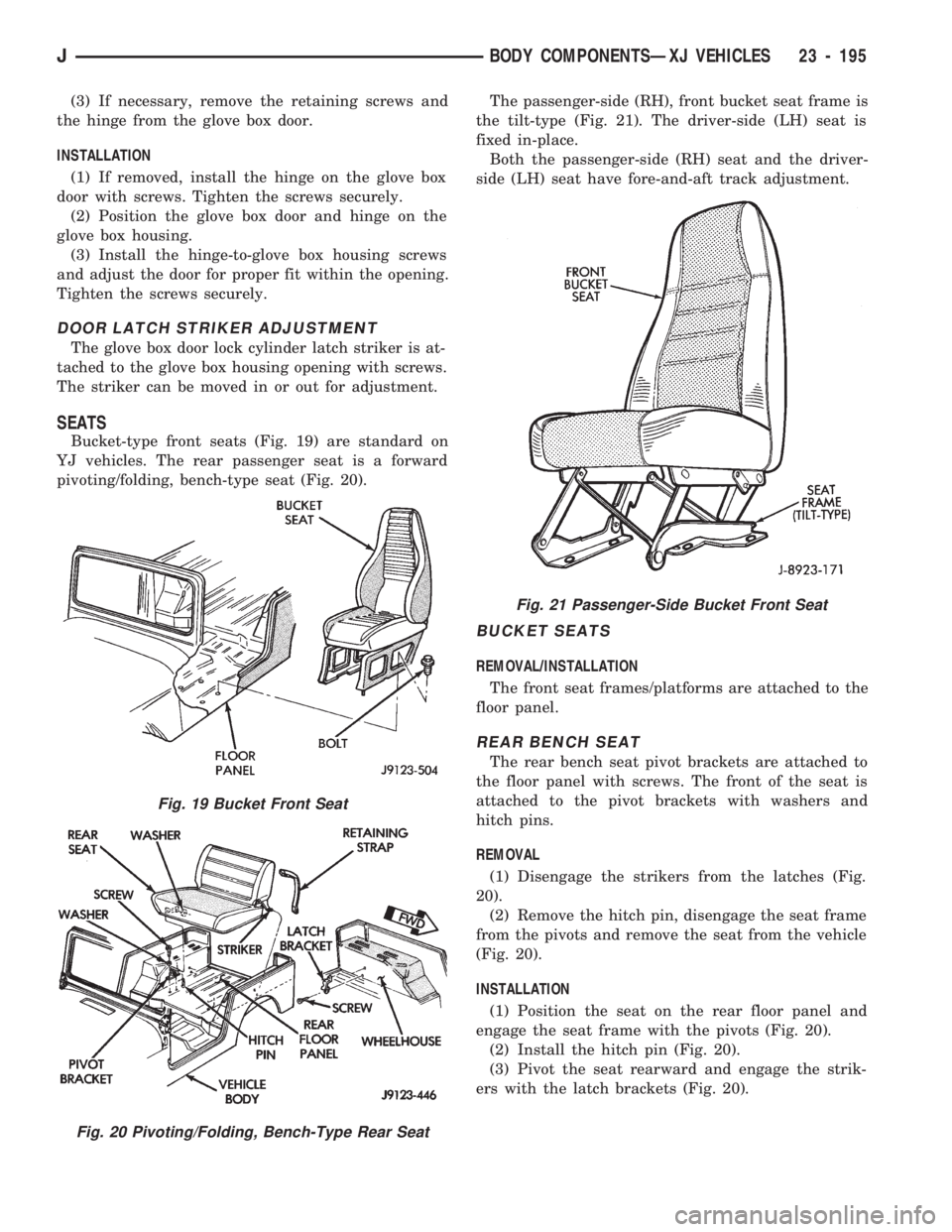
Bucket-type front seats (Fig. 19) are standard on
YJ vehicles. The rear passenger seat is a forward
pivoting/folding, bench-type seat (Fig. 20).The passenger-side (RH), front bucket seat frame is
the tilt-type (Fig. 21). The driver-side (LH) seat is
fixed in-place.
Both the passenger-side (RH) seat and the driver-
side (LH) seat have fore-and-aft track adjustment.
BUCKET SEATS
REMOVAL/INSTALLATION
The front seat frames/platforms are attached to the
floor panel.
REAR BENCH SEAT
The rear bench seat pivot brackets are attached to
the floor panel with screws. The front of the seat is
attached to the pivot brackets with washers and
hitch pins.
REMOVAL
(1) Disengage the strikers from the latches (Fig.
20).
(2) Remove the hitch pin, disengage the seat frame
from the pivots and remove the seat from the vehicle
(Fig. 20).
INSTALLATION
(1) Position the seat on the rear floor panel and
engage the seat frame with the pivots (Fig. 20).
(2) Install the hitch pin (Fig. 20).
(3) Pivot the seat rearward and engage the strik-
ers with the latch brackets (Fig. 20).
Fig. 19 Bucket Front Seat
Fig. 20 Pivoting/Folding, Bench-Type Rear Seat
Fig. 21 Passenger-Side Bucket Front Seat
JBODY COMPONENTSÐXJ VEHICLES 23 - 195