1994 JEEP CHEROKEE engine
[x] Cancel search: enginePage 23 of 1784
DRIVETRAIN
INDEX
page page
Automatic Transmission.................... 23
Drive Shafts............................ 27
Front and Rear Axles..................... 26
Hydraulic Clutch......................... 22Manual Transmission...................... 22
Rubber and Plastic Hoses/Tubing............ 28
Transfer Case........................... 25
HYDRAULIC CLUTCH
RECOMMENDED MAINTENANCE
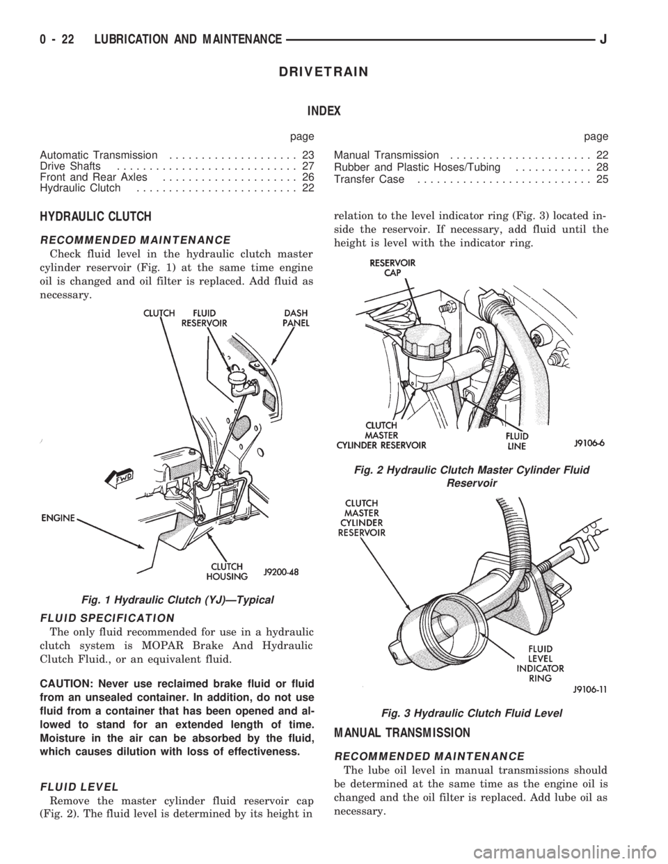
Check fluid level in the hydraulic clutch master
cylinder reservoir (Fig. 1) at the same time engine
oil is changed and oil filter is replaced. Add fluid as
necessary.
FLUID SPECIFICATION
The only fluid recommended for use in a hydraulic
clutch system is MOPAR Brake And Hydraulic
Clutch Fluid., or an equivalent fluid.
CAUTION: Never use reclaimed brake fluid or fluid
from an unsealed container. In addition, do not use
fluid from a container that has been opened and al-
lowed to stand for an extended length of time.
Moisture in the air can be absorbed by the fluid,
which causes dilution with loss of effectiveness.
FLUID LEVEL
Remove the master cylinder fluid reservoir cap
(Fig. 2). The fluid level is determined by its height inrelation to the level indicator ring (Fig. 3) located in-
side the reservoir. If necessary, add fluid until the
height is level with the indicator ring.
MANUAL TRANSMISSION
RECOMMENDED MAINTENANCE
The lube oil level in manual transmissions should
be determined at the same time as the engine oil is
changed and the oil filter is replaced. Add lube oil as
necessary.
Fig. 1 Hydraulic Clutch (YJ)ÐTypical
Fig. 2 Hydraulic Clutch Master Cylinder Fluid
Reservoir
Fig. 3 Hydraulic Clutch Fluid Level
0 - 22 LUBRICATION AND MAINTENANCEJ
Page 24 of 1784
Under normal driving conditions, manual trans-
mission lube oil should be changed after each 60
000-km (37,500 miles). With severe driving condi-
tions, after each 29 000-km (18,000 miles).
LUBRICANT SPECIFICATION
When it becomes necessary to add to or change the
lube oil in a Jeeptmanual transmission, use SAE
75W-90, API Quality Grade GL-5 gear lubricant.
LUBRICANT LEVEL
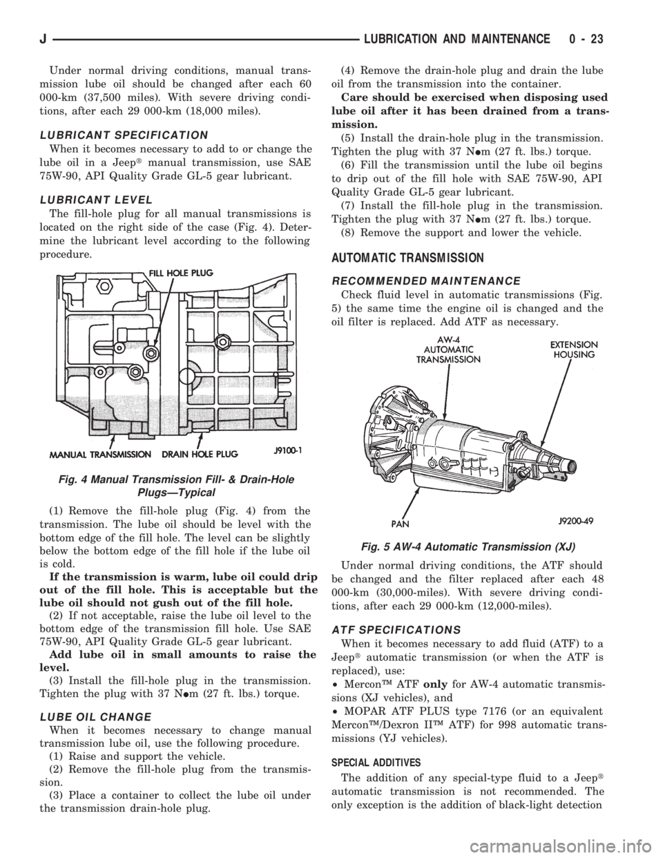
The fill-hole plug for all manual transmissions is
located on the right side of the case (Fig. 4). Deter-
mine the lubricant level according to the following
procedure.
(1) Remove the fill-hole plug (Fig. 4) from the
transmission. The lube oil should be level with the
bottom edge of the fill hole. The level can be slightly
below the bottom edge of the fill hole if the lube oil
is cold.
If the transmission is warm, lube oil could drip
out of the fill hole. This is acceptable but the
lube oil should not gush out of the fill hole.
(2) If not acceptable, raise the lube oil level to the
bottom edge of the transmission fill hole. Use SAE
75W-90, API Quality Grade GL-5 gear lubricant.
Add lube oil in small amounts to raise the
level.
(3) Install the fill-hole plug in the transmission.
Tighten the plug with 37 NIm (27 ft. lbs.) torque.
LUBE OIL CHANGE
When it becomes necessary to change manual
transmission lube oil, use the following procedure.
(1) Raise and support the vehicle.
(2) Remove the fill-hole plug from the transmis-
sion.
(3) Place a container to collect the lube oil under
the transmission drain-hole plug.(4) Remove the drain-hole plug and drain the lube
oil from the transmission into the container.
Care should be exercised when disposing used
lube oil after it has been drained from a trans-
mission.
(5) Install the drain-hole plug in the transmission.
Tighten the plug with 37 NIm (27 ft. lbs.) torque.
(6) Fill the transmission until the lube oil begins
to drip out of the fill hole with SAE 75W-90, API
Quality Grade GL-5 gear lubricant.
(7) Install the fill-hole plug in the transmission.
Tighten the plug with 37 NIm (27 ft. lbs.) torque.
(8) Remove the support and lower the vehicle.
AUTOMATIC TRANSMISSION
RECOMMENDED MAINTENANCE
Check fluid level in automatic transmissions (Fig.
5) the same time the engine oil is changed and the
oil filter is replaced. Add ATF as necessary.
Under normal driving conditions, the ATF should
be changed and the filter replaced after each 48
000-km (30,000-miles). With severe driving condi-
tions, after each 29 000-km (12,000-miles).
ATF SPECIFICATIONS
When it becomes necessary to add fluid (ATF) to a
Jeeptautomatic transmission (or when the ATF is
replaced), use:
²MerconŸ ATFonlyfor AW-4 automatic transmis-
sions (XJ vehicles), and
²MOPAR ATF PLUS type 7176 (or an equivalent
MerconŸ/Dexron IIŸ ATF) for 998 automatic trans-
missions (YJ vehicles).
SPECIAL ADDITIVES
The addition of any special-type fluid to a Jeept
automatic transmission is not recommended. The
only exception is the addition of black-light detection
Fig. 5 AW-4 Automatic Transmission (XJ)
Fig. 4 Manual Transmission Fill- & Drain-Hole
PlugsÐTypical
JLUBRICATION AND MAINTENANCE 0 - 23
Page 25 of 1784
dye to aid in detecting the source of ATF leaks. The
use of transmission sealing additives should also be
avoided.
Black-light detection dye is factory-installed in
automatic transmissions and, unless the ATF
has been drained and re-placed, it is not neces-
sary to add dye.
ATF LEVEL
Determine the ATF level according to the following
procedure.
WARNING: USE EXTREME CAUTION WHEN THE
ENGINE IS OPERATING. DO NOT PUT YOUR
HANDS NEAR THE DRIVE BELT, PULLEYS OR FAN
BLADE. DO NOT STAND IN A DIRECT LINE WITH
THE FAN BLADE.
(1) Operate the engine and allow the automatic
transmission sufficient time to warm to the normal
operating temperature (77ÉC/170ÉF).
When at normal operating temperature, ATF
will be uncomfortable to fingertips when the
dipstick is touched. Normally, 25 km (15 miles) is
a sufficient driving distance for a transmission
to warm to normal operating temperature (77ÉC/
170ÉF).
(2) Place the vehicle on a level surface.
(3) Operate the engine at idle speed.
(4) Engage the parking brake.
(5) Place a block in front of and at the rear of one
wheel/tire to prevent vehicle movement.
(6) Depress the brake pedal and move the trans-
mission selector lever through all the positions and
then place the selector lever in NEUTRAL position.
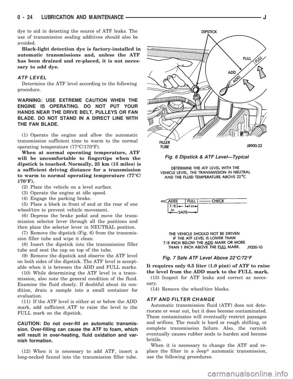
(7) Remove the dipstick (Fig. 6) from the transmis-
sion filler tube and wipe it clean.
(8) Insert the dipstick into the transmission filler
tube and seat the cap on top of the tube.
(9) Remove the dipstick and observe the ATF level
on both sides of the dipstick. The ATF level is accept-
able when it is between the ADD and FULL marks.
(10) While determining the ATF level in a trans-
mission, also note the general condition of the fluid.
Examine the fluid closely. If doubtful about its con-
dition, drain a sample into a small container for
evaluation.
(11) If the ATF level is either at or below the ADD
mark, add sufficient ATF to raise the level to the
FULL mark on the dipstick.
CAUTION: Do not over-fill an automatic transmis-
sion. Over-filling can cause the ATF to foam, which
will result in over-heating, fluid oxidation and var-
nish formation.
(12) When it is necessary to add ATF, insert a
long-necked funnel into the transmission filler tube.It requires only 0.5 liter (1.0 pint) of ATF to raise
the level from the ADD mark to the FULL mark.
(13) Inspect for ATF leaks and correct as neces-
sary.
(14) Remove the wheel/tire blocks.
ATF AND FILTER CHANGE
Automatic transmission fluid (ATF) does not dete-
riorate or wear out, but it does become contaminated.
These contaminates will eventually restrict passages
and orifices. The result is hard or rough shifting, or
complete transmission failure. Also, the varnish
eventually causes rubber seals to harden and become
brittle.
When it is necessary to change the ATF and re-
place the filter in a Jeeptautomatic transmission,
use the following procedures.
Fig. 6 Dipstick & ATF LevelÐTypical
Fig. 7 Safe ATF Level Above 22ÉC/72ÉF
0 - 24 LUBRICATION AND MAINTENANCEJ
Page 26 of 1784

DRAINING ATF/FILTER REMOVAL
Drain the automatic transmission fluid (ATF) im-
mediately after stopping the engine (before the ATF
cools).
(1) Raise and support the vehicle.
(2) Loosen the transmission pan bolts and drain
the original ATF into an appropriate container. Re-
move the pan bolts, the pan and the gasket.
Care should be exercised when disposing used
ATF after it has been drained from a vehicle
transmission.
(3) Remove the screws and the ATF filter (Fig. 8).
Discard the filter.
FILTER INSTALLATION/ATF RE-FILL
(1) Install a replacement ATF filter. Tighten the
screws with 4 NIm (35 in. lbs.) torque.
(2) Clean the pan thoroughly. Install a replace-
ment gasket on the pan. Install the pan with the at-
taching bolts:
²model AW-4 transmission Ð tighten the pan bolts
with 7 NIm (60 in. lbs.) torque; and
²model 998 transmission Ð tighten the pan bolts
with 17 NIm (150 in. lbs.) torque.
(3) Remove the support and lower the vehicle.
(4) Pour approximately 4.7 liters (5 quarts) of ATF
into the filler tube. Use MerconŸ ATF for AW-4 au-
tomatic transmissions. Use MOPAR ATF PLUS type
7176 or equivalent, for 998 automatic transmissions.
(5) Place a block in front of and at the rear of one
wheel/tire to prevent vehicle movement.
(6) Start the engine and allow it to idle a few min-
utes.
(7) Apply the brake pedal and engage the parking
brake. Move the transmission selector lever through
all positions, then place the selector lever in NEU-
TRAL position.(8) With the transmission at normal operating
temperature, observe the ATF level on the dipstick.
Add ATF (if necessary) to raise the level to the
FULL mark on the dipstick.Only 0.5 liter (1.0 pint)
will raise the level from the ADD mark to the
FULL mark when the ATF is at normal operat-
ing temperature.
(9) Inspect for fluid leaks and correct as necessary.
(10) Remove the wheel/tire blocks.
TRANSFER CASE
RECOMMENDED MAINTENANCE
The fluid (ATF) level in transfer cases should be
determined at the same time as the engine oil is
changed and the oil filter is replaced. Add ATF as
necessary.
In addition, transfer case ATF should be changed
after each 48 000-km (30,000-miles) interval of vehi-
cle operation has elapsed.
FLUID SPECIFICATIONS
If it is necessary to add fluid to a transfer case (or
when the fluid is changed), use MOPAR ATF PLUS
type 7176 or an equivalent MerconŸ/Dexron IIŸ
ATF.
FLUID LEVEL
The transfer case fill-hole plug is located at the
rear of the housing (Fig. 9).
Determine the transfer case fluid (ATF) level ac-
cording to the following procedure.
(1) Raise and support the vehicle.
(2) Remove the fill-hole plug from the transfer
case. The ATF level should be at the bottom edge of
the fill hole. The level can be slightly below the bot-
tom edge of the fill hole if the fluid is cold.
Fig. 9 Transfer CaseÐTypical
Fig. 8 ATF FilterÐTypical
JLUBRICATION AND MAINTENANCE 0 - 25
Page 27 of 1784
If the transfer case ATF is warm, it is accept-
able for the fluid to drip out of the fill hole. If
the fluid gushes out of the fill hole, the level is
too high.
(3) If the level is low, raise it to the bottom edge of
the fill hole with MOPAR ATF PLUS type 7176 or
an equivalent MerconŸ/Dexron IIŸ ATF.
(4) Install the fill-hole plug. Tighten the plug with
47 NIm (35 ft. lbs.) torque.
(5) Remove the support and lower the vehicle.
FLUID CHANGE
When it becomes necessary to change the ATF in a
Jeepttransfer case, use the following procedure.
(1) Raise and support the vehicle.
(2) Remove the fill-hole plug from the transfer
case.
(3) Place an appropriate container under the trans-
fer case drain-hole plug.
(4) Remove the drain-hole plug and drain the ATF
from the transfer case into the container.
Care should be exercised when disposing used
ATF after it has been drained from a transfer
case.
CAUTION: Do not over-tighten the drain and fill-hole
plugs. Over-tightening can strip the hole threads
and/or crack the aluminum housing.
(5) Install the drain-hole plug in the transfer case.
Tighten the plug with 47 NIm (35 ft. lbs.) torque.
(6) Fill the transfer case to the bottom edge of the
fill hole with MOPAR ATF PLUS type 7176 (or an
equivalent MerconŸ/Dexron IIŸ ATF).
(7) Install the fill-hole plug in the transfer case.
Tighten the plug with 47 NIm (35 ft. lbs.) torque.
(8) Remove the support and lower the vehicle.
FRONT AND REAR AXLES
RECOMMENDED MAINTENANCE
The lubricant level in axle differential housings
should be determined at the same time as the engine
oil is changed and the oil filter is replaced. Add lu-
bricant as necessary.
In addition, with normal driving conditions, the
axle lubricant should be changed after each 48
000-km (30,000-miles). With severe driving condi-
tions, after each 29 000-km (12,000-miles).
LUBRICANT SPECIFICATIONS
For normal vehicle operation, use SAE 75W-90,
API Quality Grade GL-5 gear lubricant in all Jeept
front (4WD only) and rear axles. Vehicles equipped
with a Trac-Loc rear axle also require a friction mod-
ifier additive with the gear lubricant.
When involved in trailer towing applications
use SAE 80W-140, API Quality Grade GL-5 gearlubricant in the rear axle. XJ Vehicles equipped
with a class III trailer hitch require SAE
75W-140 synthetic gear lubricant in the rear
axle.
LUBRICANT LEVEL
Determine the axle differential housing lubricant
level according to the following procedure.
(1) Raise and support the vehicle.
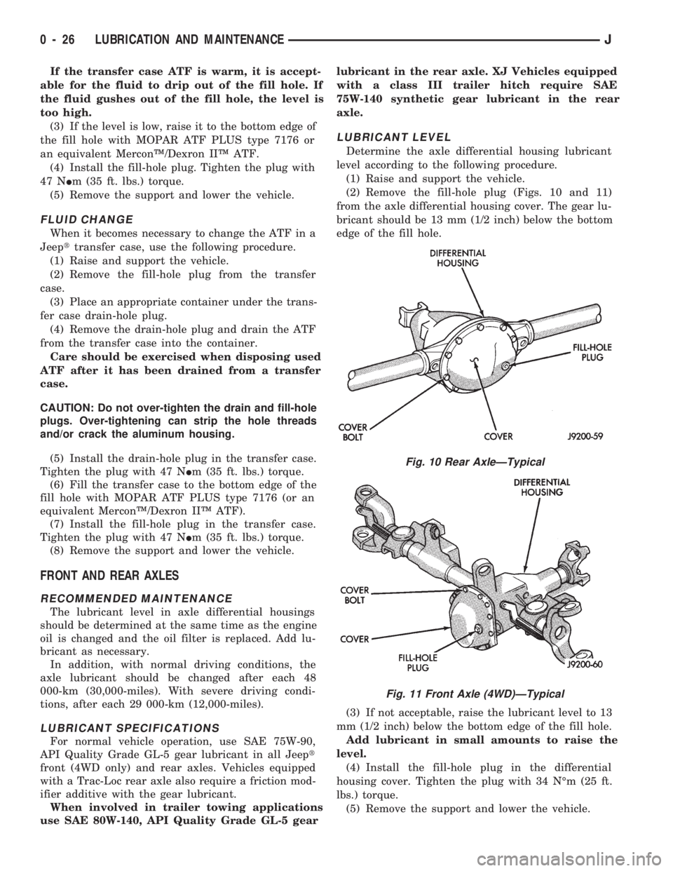
(2) Remove the fill-hole plug (Figs. 10 and 11)
from the axle differential housing cover. The gear lu-
bricant should be 13 mm (1/2 inch) below the bottom
edge of the fill hole.
(3) If not acceptable, raise the lubricant level to 13
mm (1/2 inch) below the bottom edge of the fill hole.
Add lubricant in small amounts to raise the
level.
(4) Install the fill-hole plug in the differential
housing cover. Tighten the plug with 34 NÉm (25 ft.
lbs.) torque.
(5) Remove the support and lower the vehicle.
Fig. 10 Rear AxleÐTypical
Fig. 11 Front Axle (4WD)ÐTypical
0 - 26 LUBRICATION AND MAINTENANCEJ
Page 33 of 1784
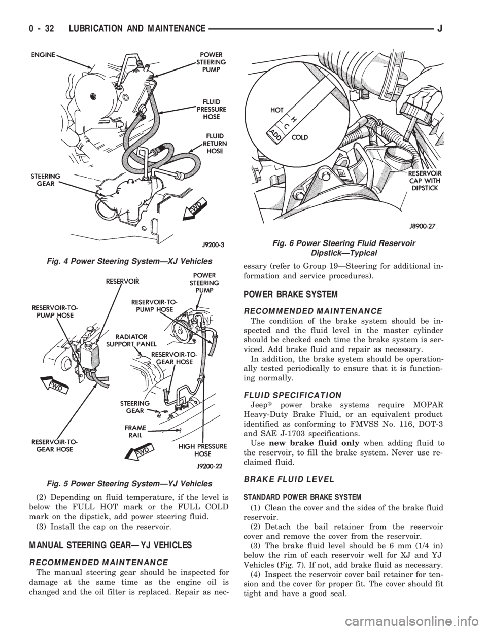
(2) Depending on fluid temperature, if the level is
below the FULL HOT mark or the FULL COLD
mark on the dipstick, add power steering fluid.
(3) Install the cap on the reservoir.
MANUAL STEERING GEARÐYJ VEHICLES
RECOMMENDED MAINTENANCE
The manual steering gear should be inspected for
damage at the same time as the engine oil is
changed and the oil filter is replaced. Repair as nec-essary (refer to Group 19ÐSteering for additional in-
formation and service procedures).
POWER BRAKE SYSTEM
RECOMMENDED MAINTENANCE
The condition of the brake system should be in-
spected and the fluid level in the master cylinder
should be checked each time the brake system is ser-
viced. Add brake fluid and repair as necessary.
In addition, the brake system should be operation-
ally tested periodically to ensure that it is function-
ing normally.
FLUID SPECIFICATION
Jeeptpower brake systems require MOPAR
Heavy-Duty Brake Fluid, or an equivalent product
identified as conforming to FMVSS No. 116, DOT-3
and SAE J-1703 specifications.
Usenew brake fluid onlywhen adding fluid to
the reservoir, to fill the brake system. Never use re-
claimed fluid.
BRAKE FLUID LEVEL
STANDARD POWER BRAKE SYSTEM
(1) Clean the cover and the sides of the brake fluid
reservoir.
(2) Detach the bail retainer from the reservoir
cover and remove the cover from the reservoir.
(3) The brake fluid level should be 6 mm (1/4 in)
below the rim of each reservoir well for XJ and YJ
Vehicles (Fig. 7). If not, add brake fluid as necessary.
(4) Inspect the reservoir cover bail retainer for ten-
sion and the cover for proper fit. The cover should fit
tight and have a good seal.
Fig. 4 Power Steering SystemÐXJ Vehicles
Fig. 5 Power Steering SystemÐYJ Vehicles
Fig. 6 Power Steering Fluid Reservoir
DipstickÐTypical
0 - 32 LUBRICATION AND MAINTENANCEJ
Page 34 of 1784
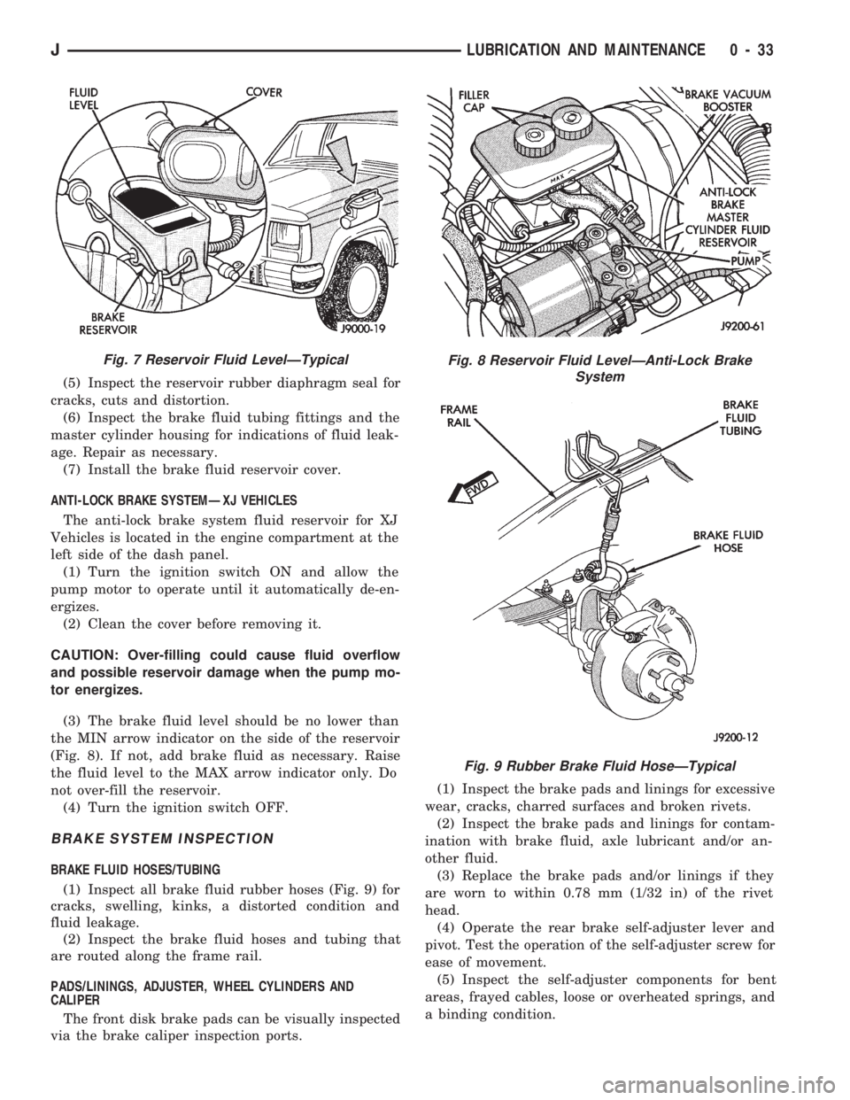
(5) Inspect the reservoir rubber diaphragm seal for
cracks, cuts and distortion.
(6) Inspect the brake fluid tubing fittings and the
master cylinder housing for indications of fluid leak-
age. Repair as necessary.
(7) Install the brake fluid reservoir cover.
ANTI-LOCK BRAKE SYSTEMÐXJ VEHICLES
The anti-lock brake system fluid reservoir for XJ
Vehicles is located in the engine compartment at the
left side of the dash panel.
(1) Turn the ignition switch ON and allow the
pump motor to operate until it automatically de-en-
ergizes.
(2) Clean the cover before removing it.
CAUTION: Over-filling could cause fluid overflow
and possible reservoir damage when the pump mo-
tor energizes.
(3) The brake fluid level should be no lower than
the MIN arrow indicator on the side of the reservoir
(Fig. 8). If not, add brake fluid as necessary. Raise
the fluid level to the MAX arrow indicator only. Do
not over-fill the reservoir.
(4) Turn the ignition switch OFF.
BRAKE SYSTEM INSPECTION
BRAKE FLUID HOSES/TUBING
(1) Inspect all brake fluid rubber hoses (Fig. 9) for
cracks, swelling, kinks, a distorted condition and
fluid leakage.
(2) Inspect the brake fluid hoses and tubing that
are routed along the frame rail.
PADS/LININGS, ADJUSTER, WHEEL CYLINDERS AND
CALIPER
The front disk brake pads can be visually inspected
via the brake caliper inspection ports.(1) Inspect the brake pads and linings for excessive
wear, cracks, charred surfaces and broken rivets.
(2) Inspect the brake pads and linings for contam-
ination with brake fluid, axle lubricant and/or an-
other fluid.
(3) Replace the brake pads and/or linings if they
are worn to within 0.78 mm (1/32 in) of the rivet
head.
(4) Operate the rear brake self-adjuster lever and
pivot. Test the operation of the self-adjuster screw for
ease of movement.
(5) Inspect the self-adjuster components for bent
areas, frayed cables, loose or overheated springs, and
a binding condition.
Fig. 7 Reservoir Fluid LevelÐTypicalFig. 8 Reservoir Fluid LevelÐAnti-Lock Brake
System
Fig. 9 Rubber Brake Fluid HoseÐTypical
JLUBRICATION AND MAINTENANCE 0 - 33
Page 35 of 1784
(6) Inspect the disc brake caliper dust boot for cor-
rect installation, damage/tears and indications of
brake fluid leakage. Inspect the bushings and pins
for corrosion, tears and a binding condition.
(7) Pull the rear wheel cylinder dust boot back to
expose the wheel cylinder housing and inspect for
fluid leaks. Inspect the pistons and cylinder bores for
proper appearance.
(8) Inspect the brake differential warning valve
and housing for indications of leakage, kinked hoses
and loose fittings.
PARK BRAKE
(1) As applicable, engage the park brake lever or
pedal and then release it.
(2) If the park brake is functioning normally, test
it for smooth operation and vehicle-holding capabil-
ity.
(3) Inspect the park brake cables for kinks, fraying
and a binding condition.
(4) With the park brake released, the rear wheels
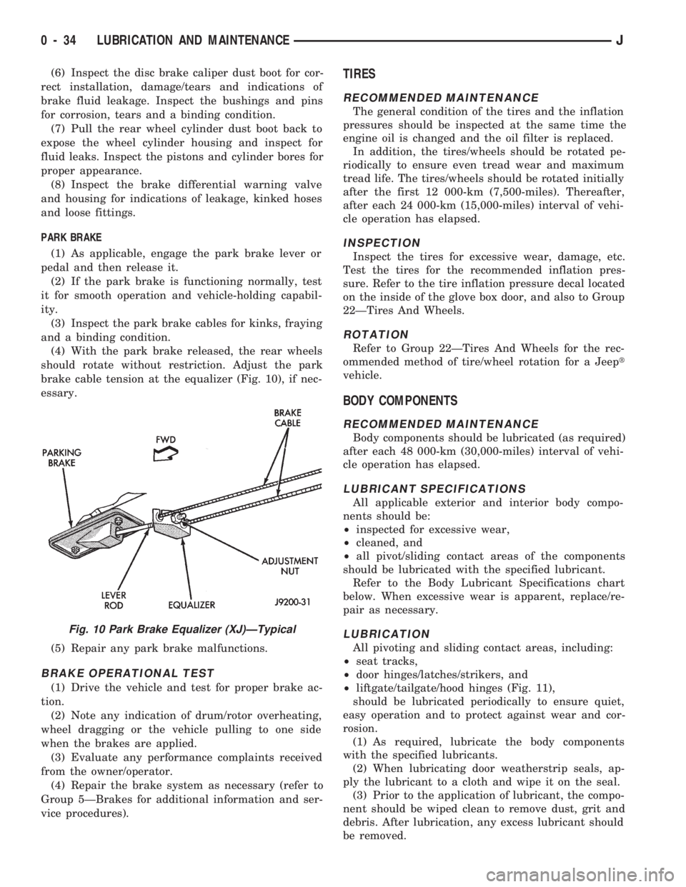
should rotate without restriction. Adjust the park
brake cable tension at the equalizer (Fig. 10), if nec-
essary.
(5) Repair any park brake malfunctions.
BRAKE OPERATIONAL TEST
(1) Drive the vehicle and test for proper brake ac-
tion.
(2) Note any indication of drum/rotor overheating,
wheel dragging or the vehicle pulling to one side
when the brakes are applied.
(3) Evaluate any performance complaints received
from the owner/operator.
(4) Repair the brake system as necessary (refer to
Group 5ÐBrakes for additional information and ser-
vice procedures).
TIRES
RECOMMENDED MAINTENANCE
The general condition of the tires and the inflation
pressures should be inspected at the same time the
engine oil is changed and the oil filter is replaced.
In addition, the tires/wheels should be rotated pe-
riodically to ensure even tread wear and maximum
tread life. The tires/wheels should be rotated initially
after the first 12 000-km (7,500-miles). Thereafter,
after each 24 000-km (15,000-miles) interval of vehi-
cle operation has elapsed.
INSPECTION
Inspect the tires for excessive wear, damage, etc.
Test the tires for the recommended inflation pres-
sure. Refer to the tire inflation pressure decal located
on the inside of the glove box door, and also to Group
22ÐTires And Wheels.
ROTATION
Refer to Group 22ÐTires And Wheels for the rec-
ommended method of tire/wheel rotation for a Jeept
vehicle.
BODY COMPONENTS
RECOMMENDED MAINTENANCE
Body components should be lubricated (as required)
after each 48 000-km (30,000-miles) interval of vehi-
cle operation has elapsed.
LUBRICANT SPECIFICATIONS
All applicable exterior and interior body compo-
nents should be:
²inspected for excessive wear,
²cleaned, and
²all pivot/sliding contact areas of the components
should be lubricated with the specified lubricant.
Refer to the Body Lubricant Specifications chart
below. When excessive wear is apparent, replace/re-
pair as necessary.
LUBRICATION
All pivoting and sliding contact areas, including:
²seat tracks,
²door hinges/latches/strikers, and
²liftgate/tailgate/hood hinges (Fig. 11),
should be lubricated periodically to ensure quiet,
easy operation and to protect against wear and cor-
rosion.
(1) As required, lubricate the body components
with the specified lubricants.
(2) When lubricating door weatherstrip seals, ap-
ply the lubricant to a cloth and wipe it on the seal.
(3) Prior to the application of lubricant, the compo-
nent should be wiped clean to remove dust, grit and
debris. After lubrication, any excess lubricant should
be removed.
Fig. 10 Park Brake Equalizer (XJ)ÐTypical
0 - 34 LUBRICATION AND MAINTENANCEJ