1994 JEEP CHEROKEE coolant
[x] Cancel search: coolantPage 136 of 1784
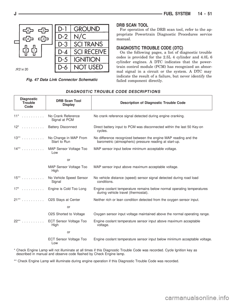
DRB SCAN TOOL
For operation of the DRB scan tool, refer to the ap-
propriate Powertrain Diagnostic Procedures service
manual.
DIAGNOSTIC TROUBLE CODE (DTC)
On the following pages, a list of diagnostic trouble
codes is provided for the 2.5L 4 cylinder and 4.0L 6
cylinder engines. A DTC indicates that the power-
train control module (PCM) has recognized an abnor-
mal signal in a circuit or the system. A DTC may
indicate the result of a failure, but never identify the
failed component directly.
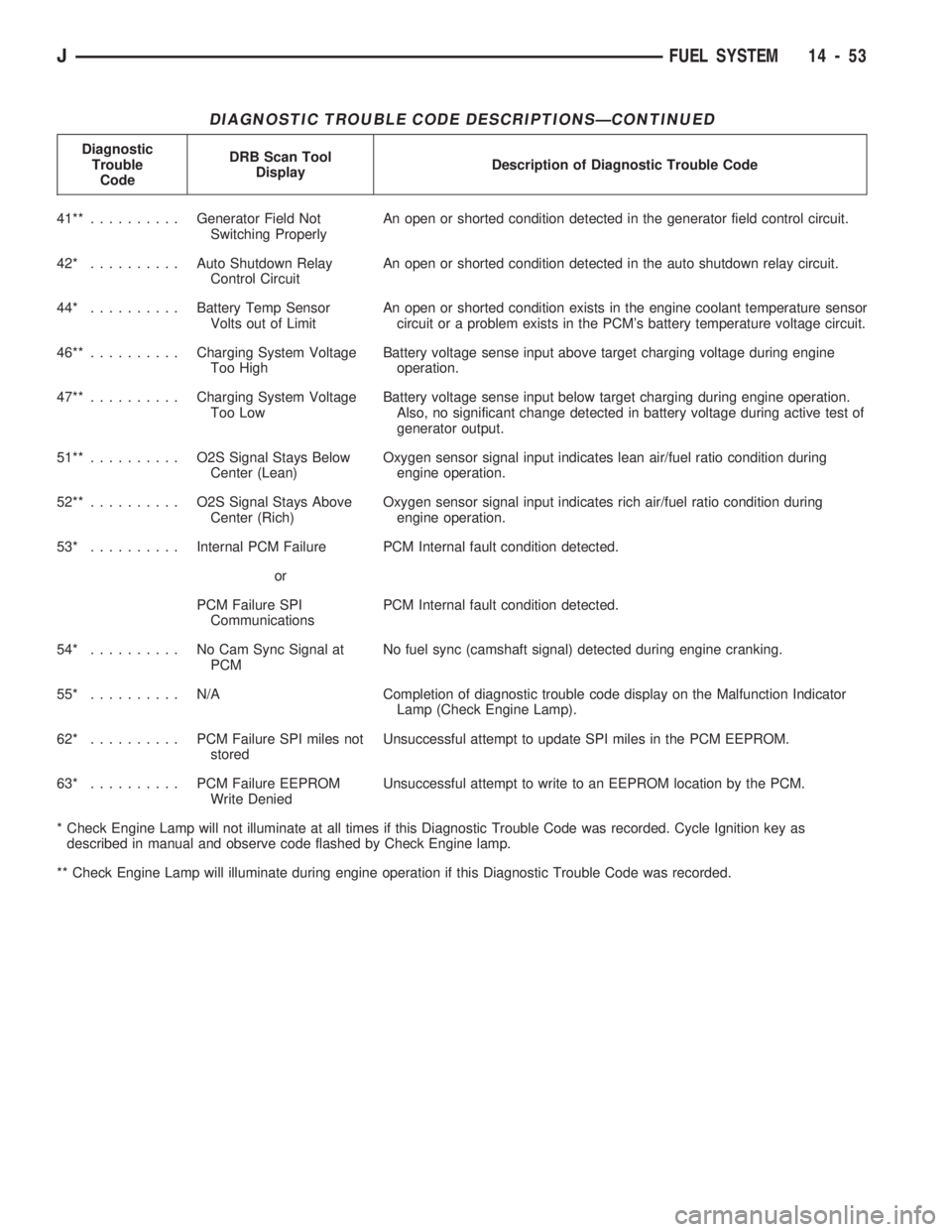
DIAGNOSTIC TROUBLE CODE DESCRIPTIONS
Diagnostic
Trouble
CodeDRB Scan Tool
DisplayDescription of Diagnostic Trouble Code
11* .......... NoCrank Reference
Signal at PCMNo crank reference signal detected during engine cranking.
12* ..........Battery Disconnect Direct battery input to PCM was disconnected within the last 50 Key-on
cycles.
13**.......... NoChange in MAP From
Start to RunNo difference recognized between the engine MAP reading and the
barometric (atmospheric) pressure reading at start-up.
14**.......... MAPSensor Voltage Too
LowMAP sensor input below minimum acceptable voltage.
or
MAP Sensor Voltage Too
HighMAP sensor input above maximum acceptable voltage.
15**.......... NoVehicle Speed Sensor
SignalNo vehicle distance (speed) sensor signal detected during road load
conditions.
17* ..........Engine is Cold Too Long Engine coolant temperature remains below normal operating temperatures
during vehicle travel (thermostat).
21**.......... O2SStays at Center Neither rich or lean condition detected from the oxygen sensor input.
or
O2S Shorted to Voltage Oxygen sensor input voltage maintained above the normal operating range.
22**.......... ECTSensor Voltage Too
HighEngine coolant temperature sensor input above maximum acceptable
voltage.
or
ECT Sensor Voltage Too
LowEngine coolant temperature sensor input below minimum acceptable voltage.
* Check Engine Lamp will not illuminate at all times if this Diagnostic Trouble Code was recorded. Cycle Ignition key as
described in manual and observe code flashed by Check Engine lamp.
** Check Engine Lamp will illuminate during engine operation if this Diagnostic Trouble Code was recorded.
Fig. 47 Data Link Connector Schematic
JFUEL SYSTEM 14 - 51
Page 138 of 1784
DIAGNOSTIC TROUBLE CODE DESCRIPTIONSÐCONTINUED
Diagnostic
Trouble
CodeDRB Scan Tool
DisplayDescription of Diagnostic Trouble Code
41**..........Generator Field Not
Switching ProperlyAn open or shorted condition detected in the generator field control circuit.
42* ..........Auto Shutdown Relay
Control CircuitAn open or shorted condition detected in the auto shutdown relay circuit.
44* ..........Battery Temp Sensor
Volts out of LimitAn open or shorted condition exists in the engine coolant temperature sensor
circuit or a problem exists in the PCM's battery temperature voltage circuit.
46**..........Charging System Voltage
Too HighBattery voltage sense input above target charging voltage during engine
operation.
47**..........Charging System Voltage
Too LowBattery voltage sense input below target charging during engine operation.
Also, no significant change detected in battery voltage during active test of
generator output.
51**.......... O2SSignal Stays Below
Center (Lean)Oxygen sensor signal input indicates lean air/fuel ratio condition during
engine operation.
52**.......... O2SSignal Stays Above
Center (Rich)Oxygen sensor signal input indicates rich air/fuel ratio condition during
engine operation.
53* ..........Internal PCM Failure PCM Internal fault condition detected.
or
PCM Failure SPI
CommunicationsPCM Internal fault condition detected.
54* .......... NoCamSync Signal at
PCMNo fuel sync (camshaft signal) detected during engine cranking.
55* .......... N/ACompletion of diagnostic trouble code display on the Malfunction Indicator
Lamp (Check Engine Lamp).
62* .......... PCMFailure SPI miles not
storedUnsuccessful attempt to update SPI miles in the PCM EEPROM.
63* .......... PCMFailure EEPROM
Write DeniedUnsuccessful attempt to write to an EEPROM location by the PCM.
* Check Engine Lamp will not illuminate at all times if this Diagnostic Trouble Code was recorded. Cycle Ignition key as
described in manual and observe code flashed by Check Engine lamp.
** Check Engine Lamp will illuminate during engine operation if this Diagnostic Trouble Code was recorded.
JFUEL SYSTEM 14 - 53
Page 139 of 1784
MULTI-PORT FUEL INJECTION (MFI)ÐCOMPONENT REMOVAL/INSTALLATION
INDEX
page page
Accelerator Pedal and Throttle Cable......... 54
Air Cleaner Housing...................... 54
Air Conditioning (A/C) Clutch Relay........... 54
Air Filter............................... 54
Automatic Shut Down (ASD) Relay........... 54
Brake Switch............................ 54
Camshaft Position Sensor.................. 54
Crankshaft Position Sensor................. 55
Engine Coolant Temperature Sensor.......... 55
Fuel Filter.............................. 55
Fuel Injector............................ 55
Fuel Pump Module....................... 56
Fuel Pump Relay........................ 56
Fuel Rail Assembly....................... 56
Fuel System Pressure Release Procedure...... 56
Fuel Tank Pressure Relief/Rollover Valve...... 56
Fuel Tanks............................. 56Fuel Tubes/Lines/Hoses and Clamps.......... 56
Idle Air Control (IAC) Motor................. 56
Ignition Coil............................. 57
Intake Air Temperature Sensor.............. 54
Intake Manifold.......................... 57
Manifold Absolute Pressure (MAP) Sensor..... 57
Oxygen (O2S) Sensor..................... 57
Park Neutral Switch....................... 58
Power Steering Pressure SwitchÐ2.5L
Engine Only........................... 58
Powertrain Control Module (PCM)............ 58
Quick-Connect Fittings..................... 59
Throttle Body............................ 59
Throttle Position Sensor (TPS).............. 59
Torque Converter Clutch Relay.............. 60
Vehicle Speed Sensor..................... 60
ACCELERATOR PEDAL AND THROTTLE CABLE
Refer to the Accelerator Pedal and Throttle Cable
section of this group for removal/installation proce-
dures.
AIR CONDITIONING (A/C) CLUTCH RELAY
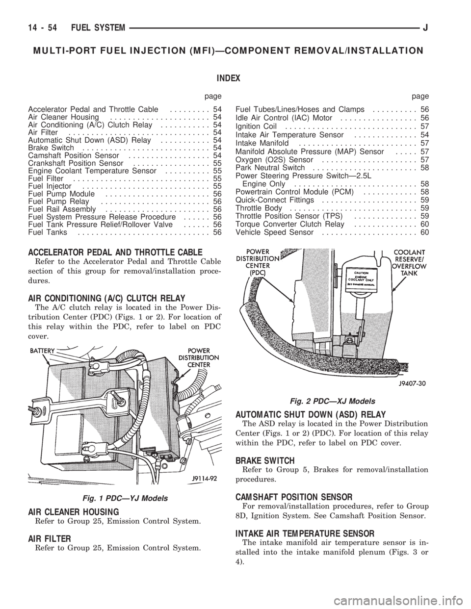
The A/C clutch relay is located in the Power Dis-
tribution Center (PDC) (Figs. 1 or 2). For location of
this relay within the PDC, refer to label on PDC
cover.
AIR CLEANER HOUSING
Refer to Group 25, Emission Control System.
AIR FILTER
Refer to Group 25, Emission Control System.
AUTOMATIC SHUT DOWN (ASD) RELAY
The ASD relay is located in the Power Distribution
Center (Figs. 1 or 2) (PDC). For location of this relay
within the PDC, refer to label on PDC cover.
BRAKE SWITCH
Refer to Group 5, Brakes for removal/installation
procedures.
CAMSHAFT POSITION SENSOR
For removal/installation procedures, refer to Group
8D, Ignition System. See Camshaft Position Sensor.
INTAKE AIR TEMPERATURE SENSOR
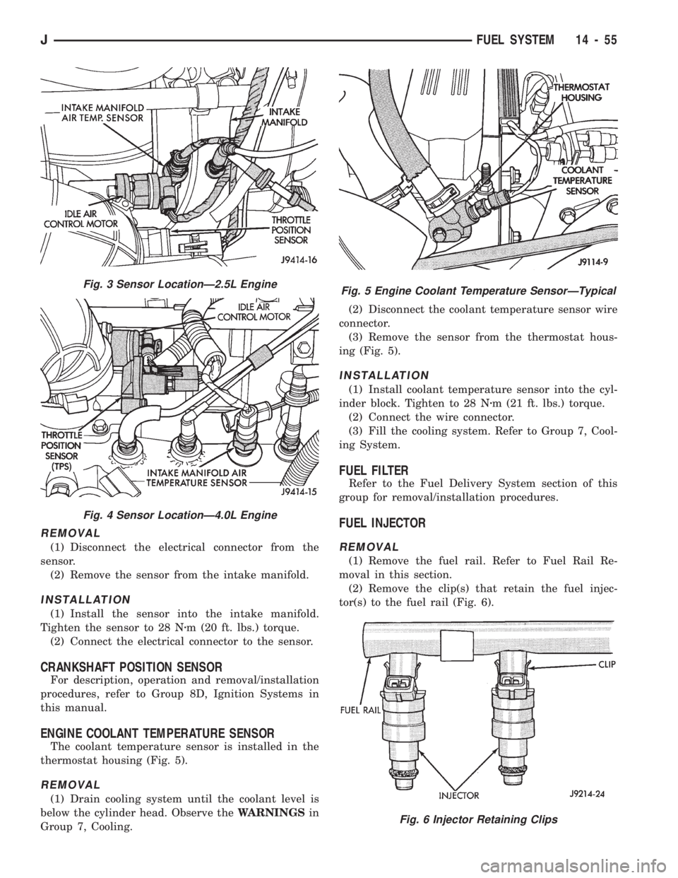
The intake manifold air temperature sensor is in-
stalled into the intake manifold plenum (Figs. 3 or
4).
Fig. 1 PDCÐYJ Models
Fig. 2 PDCÐXJ Models
14 - 54 FUEL SYSTEMJ
Page 140 of 1784
REMOVAL
(1) Disconnect the electrical connector from the
sensor.
(2) Remove the sensor from the intake manifold.
INSTALLATION
(1) Install the sensor into the intake manifold.
Tighten the sensor to 28 Nzm (20 ft. lbs.) torque.
(2) Connect the electrical connector to the sensor.
CRANKSHAFT POSITION SENSOR
For description, operation and removal/installation
procedures, refer to Group 8D, Ignition Systems in
this manual.
ENGINE COOLANT TEMPERATURE SENSOR
The coolant temperature sensor is installed in the
thermostat housing (Fig. 5).
REMOVAL
(1) Drain cooling system until the coolant level is
below the cylinder head. Observe theWARNINGSin
Group 7, Cooling.(2) Disconnect the coolant temperature sensor wire
connector.
(3) Remove the sensor from the thermostat hous-
ing (Fig. 5).
INSTALLATION
(1) Install coolant temperature sensor into the cyl-
inder block. Tighten to 28 Nzm (21 ft. lbs.) torque.
(2) Connect the wire connector.
(3) Fill the cooling system. Refer to Group 7, Cool-
ing System.
FUEL FILTER
Refer to the Fuel Delivery System section of this
group for removal/installation procedures.
FUEL INJECTOR
REMOVAL
(1) Remove the fuel rail. Refer to Fuel Rail Re-
moval in this section.
(2) Remove the clip(s) that retain the fuel injec-
tor(s) to the fuel rail (Fig. 6).
Fig. 3 Sensor LocationÐ2.5L Engine
Fig. 4 Sensor LocationÐ4.0L Engine
Fig. 5 Engine Coolant Temperature SensorÐTypical
Fig. 6 Injector Retaining Clips
JFUEL SYSTEM 14 - 55
Page 234 of 1784
COOLING SYSTEM
CONTENTS
page page
DIAGNOSIS............................. 4
ENGINE ACCESSORY DRIVE BELTS........ 31
ENGINE BLOCK HEATER................. 37GENERAL INFORMATION.................. 1
SERVICE PROCEDURES................... 9
SPECIFICATIONS....................... 38
GENERAL INFORMATION
Throughout this group, references are made to par-
ticular vehicle models by alphabetical designation
(XJ or YJ) or by the particular vehicle nameplate. A
chart showing a breakdown of alphabetical designa-
tions is included in the Introduction section at the
beginning of this manual.
COOLING SYSTEM
The cooling system regulates engine operating tem-
perature. It allows the engine to reach normal oper-
ating temperature as quickly as possible, maintains
normal operating temperature and prevents over-
heating.
The cooling system also provides a means of heat-
ing the passenger compartment and cooling the auto-
matic transmission fluid (if equipped). The cooling
system is pressurized and uses a centrifugal water
pump to circulate coolant throughout the system.
An optional factory installed heavy duty cooling
package is available on most models. The package
consists of a radiator that has an increased numberof cooling fins. XJ models equipped with a 4.0L 6 cyl-
inder engine and heavy duty cooling and/or air con-
ditioning also have an auxiliary electric cooling fan.
COOLING SYSTEM COMPONENTS
The cooling system consists of:
²A radiator
²Cooling fan (mechanical and/or electrical)
²Thermal viscous fan drive
²Fan shroud
²Radiator pressure cap
²Thermostat
²Coolant reserve/overflow system
²Transmission oil cooler (if equipped with an auto-
matic transmission)
²Coolant
²Water pump
²Hoses and hose clamps
SYSTEM COOLANT ROUTING
For cooling system flow routings, refer to Figs. 1, 2,
3or4.
JCOOLING SYSTEM 7 - 1
Page 235 of 1784
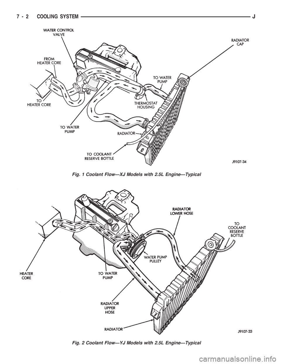
Fig. 1 Coolant FlowÐXJ Models with 2.5L EngineÐTypical
Fig. 2 Coolant FlowÐYJ Models with 2.5L EngineÐTypical
7 - 2 COOLING SYSTEMJ
Page 236 of 1784
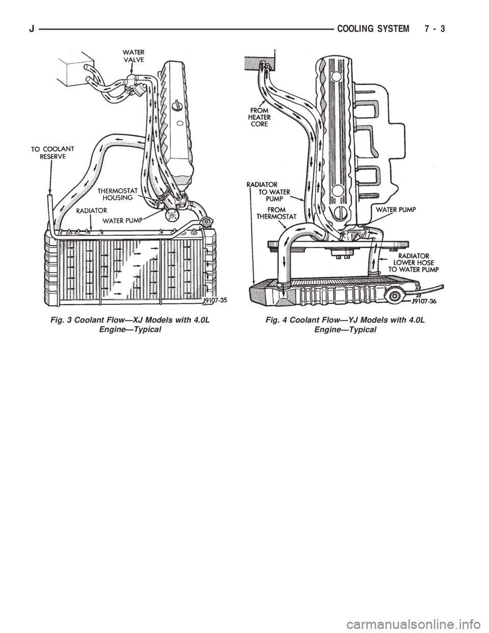
Fig. 3 Coolant FlowÐXJ Models with 4.0L
EngineÐTypicalFig. 4 Coolant FlowÐYJ Models with 4.0L
EngineÐTypical
JCOOLING SYSTEM 7 - 3
Page 242 of 1784
SERVICE PROCEDURES
INDEX
page page
Coolant................................ 15
Coolant Reserve/Overflow System............ 19
Cooling System Cleaning/Reverse Flushing..... 17
Cooling System Fans..................... 26
Cooling System Hoses.................... 26
Draining Cooling System................... 16
Radiator Pressure Cap.................... 20
Radiators............................... 22Refilling Cooling System................... 17
Testing Cooling System for Leaks............ 18
Thermostat............................. 13
Transmission Oil Coolers................... 29
Water Pump Tests........................ 9
Water PumpsÐGeneral Information............ 9
Water PumpsÐRemoval/Installation........... 10
WATER PUMPSÐGENERAL INFORMATION
A centrifugal water pump circulates coolant
through the water jackets, passages, intake manifold,
radiator core, cooling system hoses and heater core.
The pump is driven from the engine crankshaft by a
drive belt on all engines.
The water pump impeller is pressed onto the rear
of a shaft that rotates in bearings pressed into the
housing. The housing has a small hole to allow seep-
age to escape. The water pump seals are lubricated
by the antifreeze in the coolant mixture. No addi-
tional lubrication is necessary.
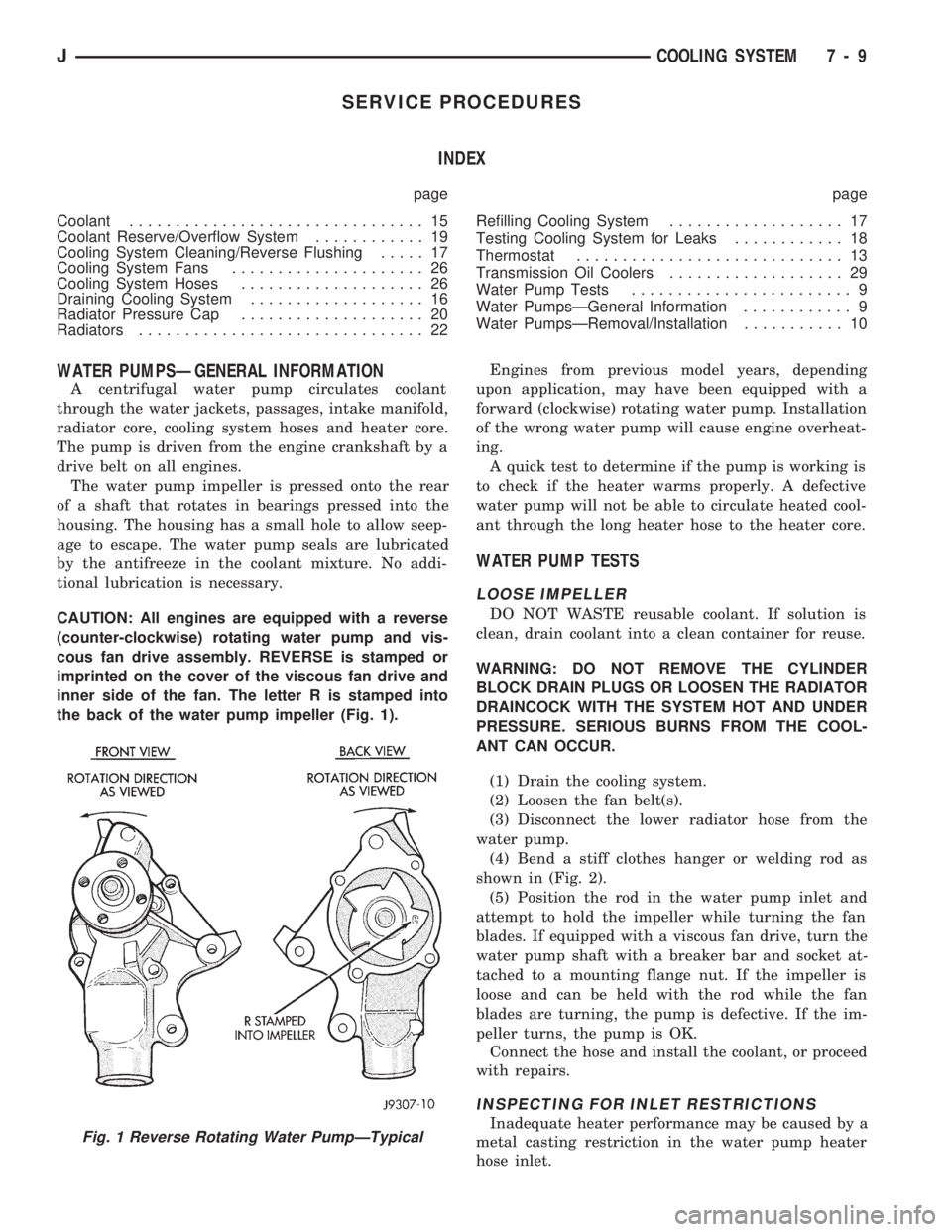
CAUTION: All engines are equipped with a reverse
(counter-clockwise) rotating water pump and vis-
cous fan drive assembly. REVERSE is stamped or
imprinted on the cover of the viscous fan drive and
inner side of the fan. The letter R is stamped into
the back of the water pump impeller (Fig. 1).Engines from previous model years, depending
upon application, may have been equipped with a
forward (clockwise) rotating water pump. Installation
of the wrong water pump will cause engine overheat-
ing.
A quick test to determine if the pump is working is
to check if the heater warms properly. A defective
water pump will not be able to circulate heated cool-
ant through the long heater hose to the heater core.
WATER PUMP TESTS
LOOSE IMPELLER
DO NOT WASTE reusable coolant. If solution is
clean, drain coolant into a clean container for reuse.
WARNING: DO NOT REMOVE THE CYLINDER
BLOCK DRAIN PLUGS OR LOOSEN THE RADIATOR
DRAINCOCK WITH THE SYSTEM HOT AND UNDER
PRESSURE. SERIOUS BURNS FROM THE COOL-
ANT CAN OCCUR.
(1) Drain the cooling system.
(2) Loosen the fan belt(s).
(3) Disconnect the lower radiator hose from the
water pump.
(4) Bend a stiff clothes hanger or welding rod as
shown in (Fig. 2).
(5) Position the rod in the water pump inlet and
attempt to hold the impeller while turning the fan
blades. If equipped with a viscous fan drive, turn the
water pump shaft with a breaker bar and socket at-
tached to a mounting flange nut. If the impeller is
loose and can be held with the rod while the fan
blades are turning, the pump is defective. If the im-
peller turns, the pump is OK.
Connect the hose and install the coolant, or proceed
with repairs.
INSPECTING FOR INLET RESTRICTIONS
Inadequate heater performance may be caused by a
metal casting restriction in the water pump heater
hose inlet.Fig. 1 Reverse Rotating Water PumpÐTypical
JCOOLING SYSTEM 7 - 9