1994 JEEP CHEROKEE engine
[x] Cancel search: enginePage 396 of 1784
perform the speed control switch test. If switch is not
at fault, then check main harness and repair as nec-
essary.
(8) Using an ohmmeter, connect one lead to a good
body ground and touch other lead to terminal in cav-
ity number 29. With brake pedal released, meter
should show continuity. When pedal is depressed,
meter should show open circuit.
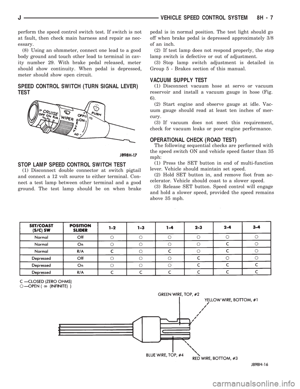
SPEED CONTROL SWITCH (TURN SIGNAL LEVER)
TEST
STOP LAMP SPEED CONTROL SWITCH TEST
(1) Disconnect double connector at switch pigtail
and connect a 12 volt source to either terminal. Con-
nect a test lamp between other terminal and a good
ground. The test lamp should be on when brakepedal is in normal position. The test light should go
off when brake pedal is depressed approximately 3/8
of an inch.
(2) If test lamp does not respond properly, the stop
lamp switch is defective or out of adjustment.
(3) Stop lamp switch adjustment is detailed in
Group 5 - Brakes section of this manual.
VACUUM SUPPLY TEST
(1) Disconnect vacuum hose at servo or vacuum
reservoir and install a vacuum gauge in hose (Fig.
6).
(2) Start engine and observe gauge at idle. Vac-
uum gauge should read at least ten inches of mer-
cury.
(3) If vacuum does not meet this requirement,
check for vacuum leaks or poor engine performance.
OPERATIONAL CHECK (ROAD TEST)
The following sequential checks are performed with
the speed switch ON and vehicle speed faster than 35
mph:
(1) Press the SET button in end of multi-function
lever. Vehicle should maintain set speed.
(2) Hold SET button in, and remove foot from ac-
celerator. Vehicle should coast to a slower speed.
(3) Release SET button. Speed control will engage
and hold a slower speed, provided the speed remains
above 35 mph.
JVEHICLE SPEED CONTROL SYSTEM 8H - 7
Page 402 of 1784

TURN SIGNALS AND HAZARD WARNING FLASHER
CONTENTS
page page
HAZARD LAMPSÐXJ.................... 1
HAZARD LAMPSÐYJ.................... 2
TURN SIGNALSÐXJ..................... 1TURN SIGNALSÐYJ..................... 2
TURN/HAZARD SWITCH REPLACEMENT - ALL
MODELS............................. 3
TURN SIGNALSÐXJ
Refer to Section 8W - Wiring Diagrams for cir-
cuit wiring diagram.
DESCRIPTION
With the turn signal lever in its up or down posi-
tion and the ignition switch in ACCESSORY or ON,
current flows through the:
²turn/hazard switch
²selected turn indicator bulb
²front and rear turn signal bulbs
²and the front side marker bulb.
With the headlamps OFF, the turn and front side
marker lamps flash in unison.With the headlamps
ON, the turn and front side marker lamps flash al-
ternately.
DIAGNOSISÐTURN SIGNAL INOPERATIVE
(1) A turn signal indicator that does not flash usu-
ally indicates a burned out turn signal bulb. Check
for and replace if defective. System should now func-
tion properly. If not, go to next step.
High generator output voltage can burn out
lamps rapidly.(2) Remove and inspect 20 amp #8 fuse. Replace if
necessary. If OK, go to next step.
(3) Remove turn flasher, light blue can, located in
upper left corner of fuse block.
(4) Turn ignition switch to ACCESSORY. Check
for battery voltage at flasher bottom cavity on fuse
block. If OK, go to next step. If not, repair open cir-
cuit in wiring between turn flasher and #8 fuse.
(5) Turn ignition switch to ACCESSORY. Move
turn signal lever up or down. Replace turn flasher
with known good flasher. The lamps should flash. If
not, replace original flasher and go to next step.
(6) Turn ignition switch to OFF. Follow procedure
for turn/hazard switch replacement to locate steering
column connector. Unplug connector.
(7) Turn ignition switch to ACCESSORY. Check
for battery voltage at connector terminal L. If OK,
replace turn/hazard switch and check that lamps
flash. If not, repair open circuit in wiring between
turn flasher and steering column connector terminal
L.
HAZARD LAMPSÐXJ
Refer to Section 8W - Wiring Diagrams for cir-
cuit wiring diagram.
DESCRIPTION
With the hazard switch ON, current flows through
the:
²hazard flasher
²the turn/hazard switch
²two front turn signal bulbs
²two rear turn signal bulbs
²two front side marker bulbs
²and two turn indicator bulbs.
All of these bulbs will flash on and off.
DIAGNOSISÐHAZARD LAMPS INOPERATIVE
(1) Inspect 20 amp #F13 fuse in Power Distribu-
tion Center (PDC). The PDC is located in the engine
compartment, passenger side. For location of fuse,check underside of PDC cover. Replace if necessary.
If OK, go to next step.
(2) Remove hazard flasher (tin can) located in fuse
block.
(3) Check for battery voltage at the terminal on
the right (3 o'clock). If OK, go to next step. If not, re-
pair open circuit in wiring between #F13 fuse and
hazard flasher right terminal.
(4) Replace hazard flasher with known good
flasher. Activate hazard warning switch. Lamps
should flash. If not, replace original flasher and go to
next step.
(5) Follow procedure for turn/hazard switch re-
placement to locate steering column connector. Un-
plug connector.
(6) Check for battery voltage at connector terminal
K. If OK, replace turn/hazard switch. If not, repair
open circuit in wiring between hazard flasher and
steering column connector terminal K.
JTURN SIGNALS AND HAZARD WARNING FLASHER 8J - 1
Page 403 of 1784

TURN SIGNALSÐYJ
Refer to Section 8W - Wiring Diagrams for cir-
cuit wiring diagram.
DESCRIPTION
With the turn signal lever in its up or down posi-
tion and the ignition switch in ACCESSORY or ON,
current flows through the:
²turn/hazard switch
²selected turn indicator bulb
²front and rear turn signal bulbs
²front side marker bulb
With the headlamps OFF, the turn and side
marker lamps flash in unison.With the headlamps
ON, the turn and side marker lamps flash alter-
nately.
DIAGNOSINGÐTURN SIGNAL INOPERATIVE
(1) A turn signal indicator that does not flash usu-
ally indicates a burned out turn signal bulb. Check
for and replace if defective. System should now func-
tion properly. If not, go to next step.
High generator output voltage can burn out
lamps rapidly.
(2) Locate fuse block under driver's side of instru-
ment panel.(3) Remove and inspect 15 amp #4 fuse. Replace if
necessary. If OK, go to next step.
(4) Remove turn flasher, light blue can, located in
fuse block.
(5) Turn ignition switch to ACCESSORY. Check
for battery voltage at cavity on left (closest to hazard
flasher can). If OK, go to next step. If not, repair
open circuit in wiring between turn flasher and #4
fuse.
(6) Turn ignition switch to ACCESSORY. Move
turn signal lever up or down. Replace turn flasher
with known good flasher. The lamps should flash. If
not, replace original flasher and go to next step.
(7) Turn ignition switch to OFF. Follow procedure
for turn/hazard switch replacement to locate steering
column connector. Unplug connector.
(8) Turn ignition switch to ACCESSORY. Check
for battery voltage at connector terminal L. If OK,
replace turn/hazard switch. If not, repair open circuit
in wiring between turn flasher and steering column
connector terminal L.
HAZARD LAMPSÐYJ
Refer to Section 8W - Wiring Diagrams for cir-
cuit wiring diagram.
DESCRIPTION
With the hazard switch ON, current flows through
the:
²hazard flasher
²turn/hazard switch
²two front turn signal bulbs
²two rear turn signal bulbs
²two front side marker bulbs
²two turn indicator bulbs.
All of these bulbs will flash on and off.
DIAGNOSISÐHAZARD LAMPS INOPERATIVE
(1) Inspect 20 amp #F5 fuse in Power Distribution
Center (PDC). The PDC is located in the engine com-
partment, passenger side. For location of fuse, check
underside of PDC cover. Replace if necessary. If OK,
go to next step.(2) Remove hazard flasher (tin can) located in fuse
block.
(3) Check for battery voltage at the terminal on
the left. If OK, go to next step. If not, repair open cir-
cuit in wiring between #F5 fuse and hazard flasher
left terminal.
(4) Replace hazard flasher with known good
flasher. Activate hazard warning switch. Lamps
should flash. If not, replace original flasher and go to
next step.
(5) Follow procedure for turn/hazard switch re-
placement to locate steering column connector. Un-
plug connector.
(6) Check for battery voltage at connector terminal
K. If OK, replace turn/hazard switch. If not, repair
open circuit in wiring between hazard flasher and
steering column connector terminal K.
8J - 2 TURN SIGNALS AND HAZARD WARNING FLASHERJ
Page 413 of 1784
(2) Install the mounting screws.
(3) Connect the wiring harness.
(4) Install the pivot pin, seal, bezel and attaching
nut (Fig. 2). Torque nut to 4 Nzm (32 in. lbs.).
(5) Connect interior washer hose.
Lubricate the bezel nipples with a small amount
of water and then install the washer hoses.
(6) Install the liftgate trim panel.
(7) Install the wiper arm assembly and connect the
external washer hose to the bezel.
(8) Slide the clip along the hose until it is over
hose mount.
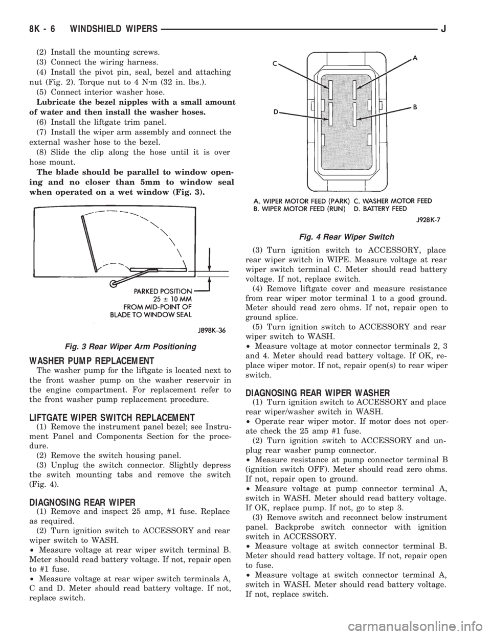
The blade should be parallel to window open-
ing and no closer than 5mm to window seal
when operated on a wet window (Fig. 3).
WASHER PUMP REPLACEMENT
The washer pump for the liftgate is located next to
the front washer pump on the washer reservoir in
the engine compartment. For replacement refer to
the front washer pump replacement procedure.
LIFTGATE WIPER SWITCH REPLACEMENT
(1) Remove the instrument panel bezel; see Instru-
ment Panel and Components Section for the proce-
dure.
(2) Remove the switch housing panel.
(3) Unplug the switch connector. Slightly depress
the switch mounting tabs and remove the switch
(Fig. 4).
DIAGNOSING REAR WIPER
(1) Remove and inspect 25 amp, #1 fuse. Replace
as required.
(2) Turn ignition switch to ACCESSORY and rear
wiper switch to WASH.
²Measure voltage at rear wiper switch terminal B.
Meter should read battery voltage. If not, repair open
to #1 fuse.
²Measure voltage at rear wiper switch terminals A,
C and D. Meter should read battery voltage. If not,
replace switch.(3) Turn ignition switch to ACCESSORY, place
rear wiper switch in WIPE. Measure voltage at rear
wiper switch terminal C. Meter should read battery
voltage. If not, replace switch.
(4) Remove liftgate cover and measure resistance
from rear wiper motor terminal 1 to a good ground.
Meter should read zero ohms. If not, repair open to
ground splice.
(5) Turn ignition switch to ACCESSORY and rear
wiper switch to WASH.
²Measure voltage at motor connector terminals 2, 3
and 4. Meter should read battery voltage. If OK, re-
place wiper motor. If not, repair open(s) to rear wiper
switch.
DIAGNOSING REAR WIPER WASHER
(1) Turn ignition switch to ACCESSORY and place
rear wiper/washer switch in WASH.
²Operate rear wiper motor. If motor does not oper-
ate check the 25 amp #1 fuse.
(2) Turn ignition switch to ACCESSORY and un-
plug rear washer pump connector.
²Measure resistance at pump connector terminal B
(ignition switch OFF). Meter should read zero ohms.
If not, repair open to ground.
²Measure voltage at pump connector terminal A,
switch in WASH. Meter should read battery voltage.
If OK, replace pump. If not, go to step 3.
(3) Remove switch and reconnect below instrument
panel. Backprobe switch connector with ignition
switch in ACCESSORY.
²Measure voltage at switch connector terminal B.
Meter should read battery voltage. If not, repair open
to fuse.
²Measure voltage at switch connector terminal A,
switch in WASH. Meter should read battery voltage.
If not, replace switch.
Fig. 3 Rear Wiper Arm Positioning
Fig. 4 Rear Wiper Switch
8K - 6 WINDSHIELD WIPERSJ
Page 420 of 1784
REAR WASHER PUMP REPLACEMENT
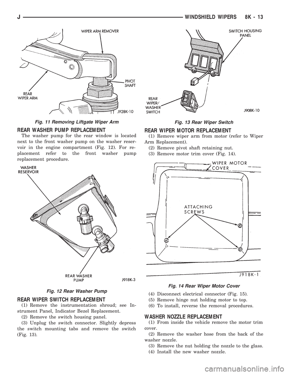
The washer pump for the rear window is located
next to the front washer pump on the washer reser-
voir in the engine compartment (Fig. 12). For re-
placement refer to the front washer pump
replacement procedure.
REAR WIPER SWITCH REPLACEMENT
(1) Remove the instrumentation shroud; see In-
strument Panel, Indicator Bezel Replacement.
(2) Remove the switch housing panel.
(3) Unplug the switch connector. Slightly depress
the switch mounting tabs and remove the switch
(Fig. 13).
REAR WIPER MOTOR REPLACEMENT
(1) Remove wiper arm from motor (refer to Wiper
Arm Replacement).
(2) Remove pivot shaft retaining nut.
(3) Remove motor trim cover (Fig. 14).
(4) Disconnect electrical connector (Fig. 15).
(5) Remove hinge nut holding motor to top.
(6) To install, reverse the removal procedures.
WASHER NOZZLE REPLACEMENT
(1) From inside the vehicle remove the motor trim
cover.
(2) Remove the washer hose from the back of the
washer nozzle.
(3) Remove the nut holding the nozzle to the glass.
(4) Install the new washer nozzle.
Fig. 11 Removing Liftgate Wiper Arm
Fig. 12 Rear Washer Pump
Fig. 13 Rear Wiper Switch
Fig. 14 Rear Wiper Motor Cover
JWINDSHIELD WIPERS 8K - 13
Page 444 of 1784
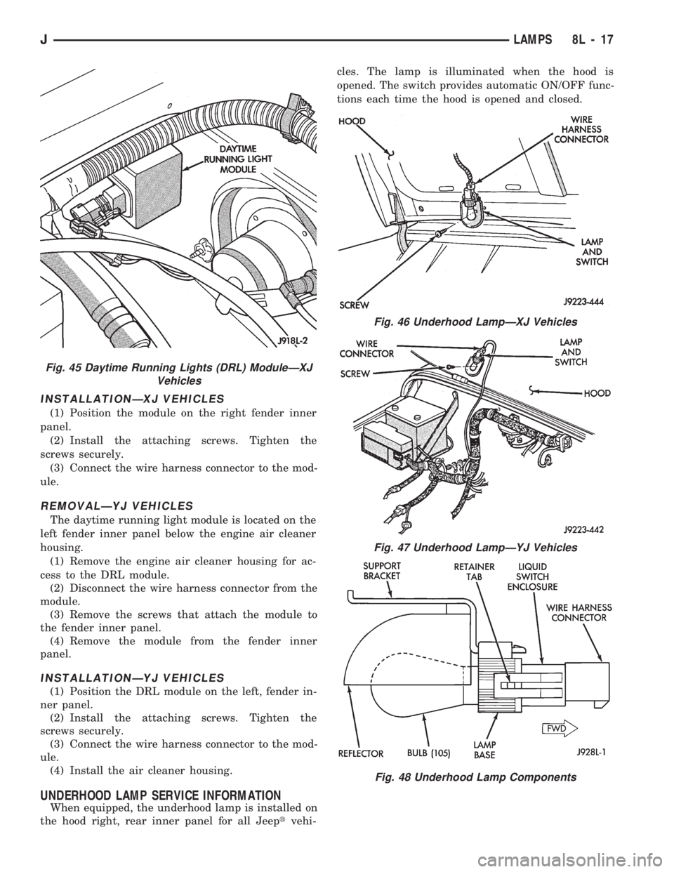
INSTALLATIONÐXJ VEHICLES
(1) Position the module on the right fender inner
panel.
(2) Install the attaching screws. Tighten the
screws securely.
(3) Connect the wire harness connector to the mod-
ule.
REMOVALÐYJ VEHICLES
The daytime running light module is located on the
left fender inner panel below the engine air cleaner
housing.
(1) Remove the engine air cleaner housing for ac-
cess to the DRL module.
(2) Disconnect the wire harness connector from the
module.
(3) Remove the screws that attach the module to
the fender inner panel.
(4) Remove the module from the fender inner
panel.
INSTALLATIONÐYJ VEHICLES
(1) Position the DRL module on the left, fender in-
ner panel.
(2) Install the attaching screws. Tighten the
screws securely.
(3) Connect the wire harness connector to the mod-
ule.
(4) Install the air cleaner housing.
UNDERHOOD LAMP SERVICE INFORMATION
When equipped, the underhood lamp is installed on
the hood right, rear inner panel for all Jeeptvehi-cles. The lamp is illuminated when the hood is
opened. The switch provides automatic ON/OFF func-
tions each time the hood is opened and closed.
Fig. 45 Daytime Running Lights (DRL) ModuleÐXJ
Vehicles
Fig. 46 Underhood LampÐXJ Vehicles
Fig. 47 Underhood LampÐYJ Vehicles
Fig. 48 Underhood Lamp Components
JLAMPS 8L - 17
Page 452 of 1784
REAR WINDOW DEFOGGER
CONTENTS
page page
GENERAL.............................. 1
XJ .................................... 4YJ .................................... 4
GENERAL
INDEX
page page
Diagnosis............................... 2
Rear Window Defogger Grid Repair........... 2Rear Window Defogger Grid Test............. 1
Switch Testing............................ 2
Using heating elements bonded to the rear window
glass, the rear defogger will clear condensation, frost
and light snow coverings from the rear window.
The horizontal grid lines and vertical bus bar lines,
printed and baked on inside surface of the rear win-
dow glass, comprise an electrical circuit. The electri-
cally conductive lines are composed of a silver-
ceramic material which when baked on glass
becomes bonded to the glass and is highly resistant
to abrasion.
The electrical current required to produce the heat
in the grid is supplied through a relay and driver op-
erated switch. When the switch is momentarily de-
pressed, the relay senses a voltage change. This
voltage change causes the relay to change state and
complete a circuit to energize the relay. Once the re-
lay energizes, the contacts close connecting the grid
to battery power.
On the XJ, the power circuit to the grid is pro-
tected by the 25 amp, #18 fuse in the fuse box.
Power for fuse #18 comes from the power distribu-
tion center, fuse #F10. Power for the relay is pro-
tected by the 20 amp, #8 fuse located in the fuse box.
On the YJ, the grid is protected by a 25 amp #6
fuse, located in the fuse box. Power for the relay is
protected by 15 amp #9 fuse, located in the fuse box.
To defog the rear window, momentarily depress the
rocker switch. A light on the rocker switch will illu-
minate indicating that the defogger is operating.
If the ignition switch is ON the first activation of
the defog/defrost feature will last for 10 minutes.
Succeeding activations will last for 5 minutes unless
the ignition switch is turned OFF; then it will recy-
cle back to 10 minutes for the first activation.To stop defogger operation, momentarily push the
switch a second time.
CAUTION: Use care when washing the inside of the
rear window to prevent damage to the defogger
heating elements. Use a soft cloth and a mild wash-
ing solution. Wiping motions should be parallel to
the heating elements. Also, keep all objects a safe
distance from the window to prevent damaging the
heating elements.
REAR WINDOW DEFOGGER GRID TEST
It is possible, that a break may exist or occur in an
individual grid line resulting in no current flow
through the line. When a grid has an open circuit,
the area of glass normally cleared by that grid re-
mains fogged or iced unless, and until it is cleared by
the adjacent grids.
With the engine running at idle, push the rear
window defogger switch to the ON position and re-
lease. The pilot lamp in the rocker switch should
light, indicating defogger operation.
Using a 12-volt DC voltmeter, contact the positive
lead to the feed side vertical bus element on the in-
side surface of the glass. Contact the negative lead to
the ground side bus element. Meter should read be-
tween 11 and 13 volts. Connect the negative lead of
the voltmeter to a good ground; the meter reading
should be constant.
Keep the negative lead connected to ground. Use
the positive lead and carefully contact each grid at
the approximate centerline of the window.
JREAR WINDOW DEFOGGER 8N - 1
Page 506 of 1784
WIRING AND COMPONENT IDENTIFICATION
CONTENTS
page page
XJ ................................... 25
XJ RHD ............................... 43YJ ................................... 13
The wiring and components shown in this section
are divided into sections by vehicle line. When locat-
ing a specific wire routing or component, first turn to
the appropriate index, then look up thefigure num-
berthat refers to the component.Page numbers at
the top of the page do not refer to figure num-
bers.
YJ
Caption Fig.
Battery and Starter Wiring.......................8
Body Wiring...............................1,2
Chassis Wiring...............................3
Engine Compartment Wiring......................7
Engine Wiring 2.5L...........................10Caption Fig.
Engine Wiring 4.0L...........................11
Front End Wiring.............................12
Instrument Panel Wiring.......................5,6
Steering Column Wiring.........................4
Transmission Wiring...........................9
JWIRING AND COMPONENT IDENTIFICATION 8W - 13