1994 JEEP CHEROKEE engine oil
[x] Cancel search: engine oilPage 1286 of 1784
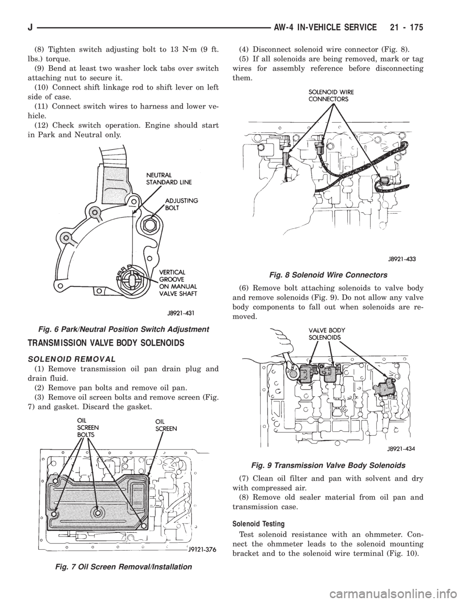
(8) Tighten switch adjusting bolt to 13 Nzm(9ft.
lbs.) torque.
(9) Bend at least two washer lock tabs over switch
attaching nut to secure it.
(10) Connect shift linkage rod to shift lever on left
side of case.
(11) Connect switch wires to harness and lower ve-
hicle.
(12) Check switch operation. Engine should start
in Park and Neutral only.
TRANSMISSION VALVE BODY SOLENOIDS
SOLENOID REMOVAL
(1) Remove transmission oil pan drain plug and
drain fluid.
(2) Remove pan bolts and remove oil pan.
(3) Remove oil screen bolts and remove screen (Fig.
7) and gasket. Discard the gasket.(4) Disconnect solenoid wire connector (Fig. 8).
(5) If all solenoids are being removed, mark or tag
wires for assembly reference before disconnecting
them.
(6) Remove bolt attaching solenoids to valve body
and remove solenoids (Fig. 9). Do not allow any valve
body components to fall out when solenoids are re-
moved.
(7) Clean oil filter and pan with solvent and dry
with compressed air.
(8) Remove old sealer material from oil pan and
transmission case.
Solenoid Testing
Test solenoid resistance with an ohmmeter. Con-
nect the ohmmeter leads to the solenoid mounting
bracket and to the solenoid wire terminal (Fig. 10).
Fig. 8 Solenoid Wire Connectors
Fig. 9 Transmission Valve Body Solenoids
Fig. 6 Park/Neutral Position Switch Adjustment
Fig. 7 Oil Screen Removal/Installation
JAW-4 IN-VEHICLE SERVICE 21 - 175
Page 1295 of 1784
(3) Tighten adaptor housing bolts to 34 Nzm (25 ft.
lbs.) torque.
(4) Install components removed to gain access to
rotor and drive gear.
THROTTLE POSITION SENSOR (TPS) SERVICE
A separate throttle position sensor is used for au-
tomatic transmission applications. The sensor is at-
tached to the base of the throttle body. Refer to
Group 14 for TPS service and adjustment.
TRANSMISSION THROTTLE CABLE REPLACEMENT
THROTTLE CABLE REMOVAL
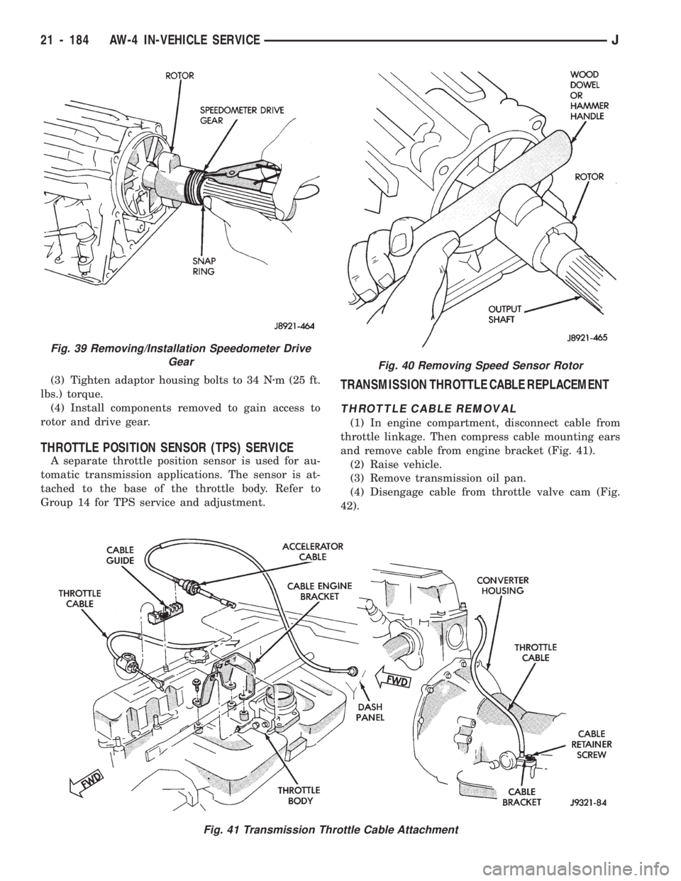
(1) In engine compartment, disconnect cable from
throttle linkage. Then compress cable mounting ears
and remove cable from engine bracket (Fig. 41).
(2) Raise vehicle.
(3) Remove transmission oil pan.
(4) Disengage cable from throttle valve cam (Fig.
42).
Fig. 41 Transmission Throttle Cable Attachment
Fig. 40 Removing Speed Sensor Rotor
Fig. 39 Removing/Installation Speedometer Drive
Gear
21 - 184 AW-4 IN-VEHICLE SERVICEJ
Page 1296 of 1784
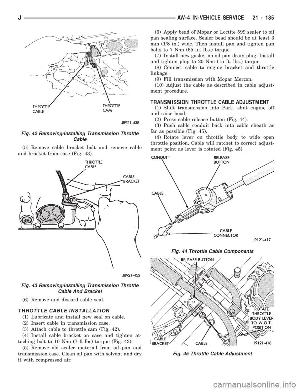
(5) Remove cable bracket bolt and remove cable
and bracket from case (Fig. 43).
(6) Remove and discard cable seal.
THROTTLE CABLE INSTALLATION
(1) Lubricate and install new seal on cable.
(2) Insert cable in transmission case.
(3) Attach cable to throttle cam (Fig. 42).
(4) Install cable bracket on case and tighten at-
taching bolt to 10 Nzm (7 ft-lbs) torque (Fig. 43).
(5) Remove old sealer material from oil pan and
transmission case. Clean oil pan with solvent and dry
it with compressed air.(6) Apply bead of Mopar or Loctite 599 sealer to oil
pan sealing surface. Sealer bead should be at least 3
mm (1/8 in.) wide. Then install pan and tighten pan
bolts to 7 Nzm (65 in. lbs.) torque.
(7) Install new gasket on oil pan drain plug. Install
and tighten plug to 20 Nzm (15 ft. lbs.) torque.
(8) Connect cable to engine bracket and throttle
linkage.
(9) Fill transmission with Mopar Mercon.
(10) Adjust the cable as described in cable adjust-
ment procedure.
TRANSMISSION THROTTLE CABLE ADJUSTMENT
(1) Shift transmission into Park, shut engine off
and raise hood.
(2) Press cable release button (Fig. 44).
(3) Push cable conduit back into cable sheath as
far as possible (Fig. 45).
(4) Rotate lever on throttle body to wide open
throttle position. Cable will ratchet to correct adjust-
ment point as lever is rotated (Fig. 45).
Fig. 42 Removing/Installing Transmission Throttle
Cable
Fig. 43 Removing/Installing Transmission Throttle
Cable And Bracket
Fig. 44 Throttle Cable Components
Fig. 45 Throttle Cable Adjustment
JAW-4 IN-VEHICLE SERVICE 21 - 185
Page 1298 of 1784
TRANSMISSION COOLER SERVICE
Main Cooler
The transmission main cooler is located in the ra-
diator. The main cooler can be flushed when neces-
sary, however, the cooler is not a repairable
component. If the cooler is damaged, plugged, or
leaking, the radiator will have to be replaced.
Auxiliary Cooler
The auxiliary cooler is mounted in front of the ra-
diator at the driver side of the vehicle (Fig. 48). The
cooler can be flushed when necessary, while mounted
in the vehicle. The cooler can also be removed for ac-
cess, repair, or replacement as needed.
The main and auxiliary coolers should both be
flushed whenever a transmission or converter clutch
malfunction generates sludge, debris, or particles of
clutch friction material.
Cooler Service
The main cooler (and radiator) and the auxiliary
cooler can be removed for service or access to other
components. Auxiliary cooler removal requires that
the front bumper and radiator support be removed
for access to the cooler lines and attaching bracket.
REVERSE FLUSHING MAIN AND AUXILIARY
COOLERS AND COOLER LINES
Reverse flushing the cooler and lines will prevent
sludge and particles from flowing back into the
transmission after repair. The flushing procedure ap-
plies to standard (in-radiator) coolers and auxiliary
coolers equally.
Pressure equipment is preferred for reverse flush-
ing. However, reverse flushing can be performed us-
ing hand operated equipment as described in the
following procedure.
(1) Disconnect cooler lines at transmission and at
auxiliary cooler (Figs. 48 and 49).
(2) Position drain pan under cooler line to catch
material flushed through coolers and lines.
(3) Reverse flush each cooler using hand operated
suction gun filled with mineral spirits. Insert gun
nozzle (or hose) into cooler inlet (return) line. Then
force mineral spirits through into line and through
cooler.(4) Continue reverse flushing until fluid exiting in-
let (pressure) line is clear and free of debris/residue.
(5) Replace radiator if fluid cannot be pumped
through main cooler. Replace auxiliary cooler if leaks
are evident, or if fluid cannot be pumped through it.
(6) Clear flushing materials from coolers and lines
with short pulses of compressed air. Insert air gun
nozzle into cooler inlet (return) line and continue
short pulses of air until all fluid is cleared from
cooler and lines.
(7) Pump one quart of fresh automatic transmis-
sion fluid through cooler and lines before reconnect-
ing cooler lines.
FLOW TESTING TRANSMISSION MAIN
COOLER
Cooler flow is checked by measuring the amount of
fluid flow through the cooler in a 20 second time pe-
riod. The test is performed with the engine running
and transmission in neutral. Fluid is then pumped
through the cooler by the transmission oil pump.
(1) Disconnect cooler inlet line at transmission fit-
ting.
(2) Securely attach hose to end of inlet line and po-
sition line in a one quart test container.
(3) Add extra quart of fluid to transmission.
(4) Use stopwatch to check flow test time.
(5) Shift transmission into neutral and set parking
brake.
(6) Start and run engine at curb idle speed and im-
mediately note cooler flow. Approximately one quart
of fluid should flow into test container in 20 second
period.
(7) If cooler flow is intermittent, flows less than
one quart in 20 seconds, or does not flow at all,
cooler is faulty and must be replaced.
TRANSMISSION COOLER LINE FITTINGS
Quick disconnect fittings are used at the transmis-
sion cooler line connections. The fitting seals and
guides are serviceable.
Replace the seals and guides whenever the fittings
exhibit leakage, or will not properly snap into place.
JAW-4 IN-VEHICLE SERVICE 21 - 187
Page 1300 of 1784
AW-4 TRANSMISSION REMOVAL AND INSTALLATION
INDEX
page page
Oil Pump Seal Replacement............... 189
Torque Converter Stator Clutch Inspection..... 189Transmission and Torque Converter Installation . 190
Transmission and Torque Converter Removal . . 189
TRANSMISSION AND TORQUE CONVERTER
REMOVAL
(1) Raise vehicle.
(2) Drain transmission fluid and reinstall oil pan
drain plug.
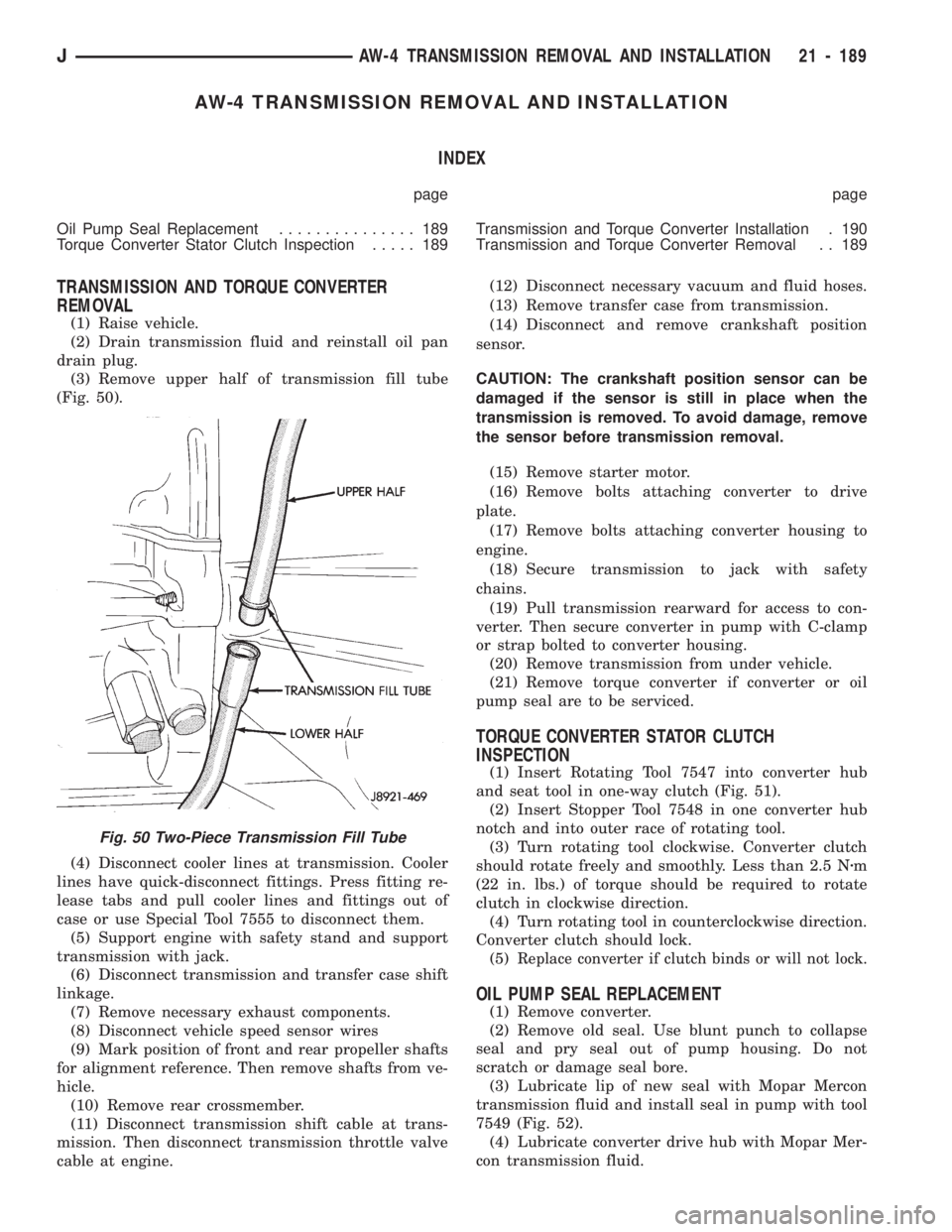
(3) Remove upper half of transmission fill tube
(Fig. 50).
(4) Disconnect cooler lines at transmission. Cooler
lines have quick-disconnect fittings. Press fitting re-
lease tabs and pull cooler lines and fittings out of
case or use Special Tool 7555 to disconnect them.
(5) Support engine with safety stand and support
transmission with jack.
(6) Disconnect transmission and transfer case shift
linkage.
(7) Remove necessary exhaust components.
(8) Disconnect vehicle speed sensor wires
(9) Mark position of front and rear propeller shafts
for alignment reference. Then remove shafts from ve-
hicle.
(10) Remove rear crossmember.
(11) Disconnect transmission shift cable at trans-
mission. Then disconnect transmission throttle valve
cable at engine.(12) Disconnect necessary vacuum and fluid hoses.
(13) Remove transfer case from transmission.
(14) Disconnect and remove crankshaft position
sensor.
CAUTION: The crankshaft position sensor can be
damaged if the sensor is still in place when the
transmission is removed. To avoid damage, remove
the sensor before transmission removal.
(15) Remove starter motor.
(16) Remove bolts attaching converter to drive
plate.
(17) Remove bolts attaching converter housing to
engine.
(18) Secure transmission to jack with safety
chains.
(19) Pull transmission rearward for access to con-
verter. Then secure converter in pump with C-clamp
or strap bolted to converter housing.
(20) Remove transmission from under vehicle.
(21) Remove torque converter if converter or oil
pump seal are to be serviced.
TORQUE CONVERTER STATOR CLUTCH
INSPECTION
(1) Insert Rotating Tool 7547 into converter hub
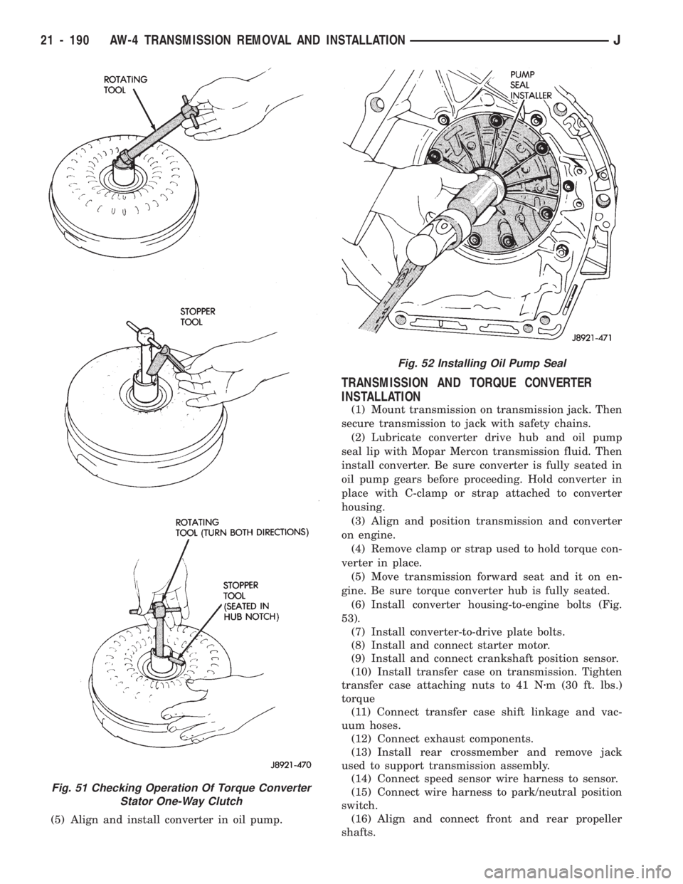
and seat tool in one-way clutch (Fig. 51).
(2) Insert Stopper Tool 7548 in one converter hub
notch and into outer race of rotating tool.
(3) Turn rotating tool clockwise. Converter clutch
should rotate freely and smoothly. Less than 2.5 Nzm
(22 in. lbs.) of torque should be required to rotate
clutch in clockwise direction.
(4) Turn rotating tool in counterclockwise direction.
Converter clutch should lock.
(5)
Replace converter if clutch binds or will not lock.
OIL PUMP SEAL REPLACEMENT
(1) Remove converter.
(2) Remove old seal. Use blunt punch to collapse
seal and pry seal out of pump housing. Do not
scratch or damage seal bore.
(3) Lubricate lip of new seal with Mopar Mercon
transmission fluid and install seal in pump with tool
7549 (Fig. 52).
(4) Lubricate converter drive hub with Mopar Mer-
con transmission fluid.
Fig. 50 Two-Piece Transmission Fill Tube
JAW-4 TRANSMISSION REMOVAL AND INSTALLATION 21 - 189
Page 1301 of 1784
(5) Align and install converter in oil pump.
TRANSMISSION AND TORQUE CONVERTER
INSTALLATION
(1) Mount transmission on transmission jack. Then
secure transmission to jack with safety chains.
(2) Lubricate converter drive hub and oil pump
seal lip with Mopar Mercon transmission fluid. Then
install converter. Be sure converter is fully seated in
oil pump gears before proceeding. Hold converter in
place with C-clamp or strap attached to converter
housing.
(3) Align and position transmission and converter
on engine.
(4) Remove clamp or strap used to hold torque con-
verter in place.
(5) Move transmission forward seat and it on en-
gine. Be sure torque converter hub is fully seated.
(6)
Install converter housing-to-engine bolts (Fig.
53).
(7) Install converter-to-drive plate bolts.
(8) Install and connect starter motor.
(9) Install and connect crankshaft position sensor.
(10) Install transfer case on transmission. Tighten
transfer case attaching nuts to 41 Nzm (30 ft. lbs.)
torque
(11) Connect transfer case shift linkage and vac-
uum hoses.
(12) Connect exhaust components.
(13) Install rear crossmember and remove jack
used to support transmission assembly.
(14) Connect speed sensor wire harness to sensor.
(15) Connect wire harness to park/neutral position
switch.
(16) Align and connect front and rear propeller
shafts.
Fig. 51 Checking Operation Of Torque Converter
Stator One-Way Clutch
Fig. 52 Installing Oil Pump Seal
21 - 190 AW-4 TRANSMISSION REMOVAL AND INSTALLATIONJ
Page 1669 of 1784
(18) Disconnect the charging hoses from the ser-
vice valves.
COMPRESSOR OIL LEVEL
The compressor oil level must be checked and ad-
justed if the system has been discharged rapidly, or
when a component has been replaced. If a replace-
ment compressor is being installed, it must be filled
with new compressor oil (Suniso 5GS, or equivalent).
The normal quantity of oil required for the com-
pressor and entire system is 136 ml (4.6 fluid oz.) for
SD 709 compressor. DO NOT overfill the compressor.
Excessive amounts of oil in the system will hinder
compressor operation and reduce A/C performance.
CAUTION: The compressor is a high speed unit.
Satisfactory operation is dependent on sufficient lu-
brication; however, excess oil will hinder A/C per-
formance.
Two oil level checking procedures are necessary.
Use Procedure (A) when the compressor is being re-
placed and the system was discharged properly (no
oil loss). Use Procedure (B) for routine maintenance
or when checking oil level after replacing a system
component.
In cases where rapid loss of refrigerant and oil
occurred, the system must be evacuated and
purged. Then the compressor must be filled with
the necessary amount of oil to fill the entire sys-
tem.
PROCEDURE A
(1) Remove the oil filler plug, discharge cap and
suction port caps from the original and replacement
compressor.
(2) Use a clean container to drain the oil from the
replacement compressor. Drain the oil through the
oil filler plug hole, the discharge and suction. Then
rotate clutch front plate several times to push the oil
on cylinder out to discharge chamber of cylinder
head and drain the oil from discharge port.
(3) Drain the oil from the original compressor into
a measuring cup or graduated beaker in the same
way as Step 2. Note the amount of oil drained.
(4) Fill the replacement compressor with the same
amount of oil drained from the original compressor
plus 30 ml (1 fluid oz.).
FOR EXAMPLE:ÐIf the old compressor contained
103.5 ml (3.5 fluid oz.) of oil, fill the replacement
compressor with a total of 133 ml (4.5 fluid oz.) of oil.
PROCEDURE B
(1) Start the engine and operate the engine at idle.
(2) Operate the air conditioning system for 10 min-
utes to return the maximum amount of oil in the sys-
tem to the compressor.(3) Stop the engine and disconnect the magnetic
clutch feed wire.
(4) Front-seat the discharge and suction service
valves.
(5) Determine the mounting angle.
(a) Position an Angle Gauge across the flat sur-
faces of the front mounting ears.
(b) Center the bubble.
(c) Read the mounting angle to the closest de-
gree.
(d) These vehicles should have 0É mounting an-
gle.
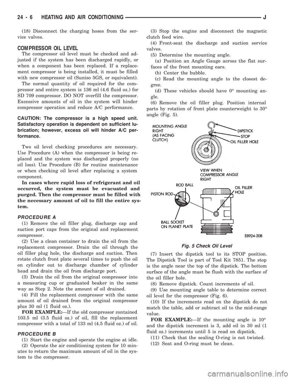
(6) Remove the oil filler plug. Position internal
parts by rotation of front plate counterweight to 30É
angle (Fig. 5).
(7) Insert the dipstick tool to its STOP position.
The Dipstick Tool is part of Tool Kit 7851. The stop
is the angle near the top of the dipstick. The bottom
surface of the angle must be flush with the surface of
the oil filler hole.
(8) Remove dipstick. Count increments of oil.
(9) Use mounting angle table to determine correct
oil level for the compressor (Fig. 6).
(10) If the increments read on the dipstick do not
match the table, add or subtract oil to the mid-range
value.
FOR EXAMPLE:ÐIf the mounting angle is 10É
and the dipstick increment is 3, add oil in 30 ml (1
fluid oz.) increments until 5 is read on dipstick.
(11) Check that the sealing O-ring is not twisted.
(12) Seat and O-ring must be clean.
Fig. 5 Check Oil Level
24 - 6 HEATING AND AIR CONDITIONINGJ
Page 1677 of 1784
SERVICE DIAGNOSISÐELECTRICAL
BLOWER CONTROLSÐXJ VEHICLES
DESCRIPTION
The blower motor delivers air to the inside of the
vehicle. Its speed is controlled by the blower switch
and the blower resistors. With the switch in LO, part
of the battery voltage is supplied to the motor
through all of the resistors. The motor runs slowly.
As the blower switch is moved to a higher speed, the
switch allows more voltage to be applied to the
blower motor, which will increase its speed. When
the switch is in HI, the blower resistors are bypassed
and battery voltage is applied directly to the blower
motor. The motor runs at the fastest speed in this
mode.
DIAGNOSIS
Refer to the Group 8W, Wiring Diagrams for com-
plete system schematic.
1. BLOWER MOTOR INOPERATIVE
²Remove and inspect fuse. If the fuse is blown, re-
place fuse.
2. BLOWER MOTOR INOPERATIVE (HI Posi-
tion)
Put the ignition switch in RUN, the select switch
in HEAT and the blower switch on HI.
²Blower motor connector (Terminal A) should be
battery voltage. If not go to next step.
²Blower motor connector (Terminal B) should be 0
ohms. If not, repair wire to ground.
²Blower switch connector (Terminal C) should be
battery voltage. If battery voltage replace blower
switch. If not, replace select switch.
3. BLOWER MOTOR INOPERATIVE (LO, M1
& M2 Positions)
Ignition switch in RUN, select switch in HEAT.
²Blower resistors connector (Terminal D) should be
battery voltage. If not, replace select switch.
²Blower resistors connector (Terminal C) should be
battery voltage. If not, replace blower switch.
²Blower resistors connector (Terminal A) should be
battery voltage. If not, replace blower switch.
²Blower resistors connector (Terminal B) should be
battery voltage. If not, replace blower resistor.
AIR CONDITIONING SYSTEMÐXJ VEHICLES
DESCRIPTION
The A/C Compressor Clutch is belt-driven by the
engine. A clutch, operated by a solenoid, automati-
cally turns the compressor on and off to control evap-
orator icing.
The A/C Compressor Clutch operation is controlled
by several components: the A/C Low-Pressure
Switch, Thermostat Switch, Fuel Pump Relay, A/C
Clutch Relay and the Engine Controller.The A/C low pressure switch opens when there is
not enough refrigerant in the system. When this hap-
pens, voltage is no longer present at the Engine Con-
troller. The Engine Controller will turn off the A/C
clutch relay. With the proper refrigerant level in the
system, the low pressure switch remains closed.
When the evaporator temperature is low enough to
ice the cooling coils, the thermostat switch opens.
The Engine Controller will turn off the A/C clutch.
The thermostat switch closes when the temperature
rises. The Engine Controller will then turn the A/C
clutch relay on again.
DIAGNOSIS
Refer to the Group 8W, Wiring Diagrams for com-
plete system schematic.
With engine running, Engine Controller may delay
A/C clutch up to 30 seconds.
1. A/C COMPRESSOR CLUTCH INOPERA-
TIVE
Clutch connector disconnected.
²Jumper fused test lead, battery to clutch connec-
tor, clutch should operate. If not, replace compressor
clutch assembly.
2. A/C LOW PRESSURE SWITCH
Ignition in RUN, A/C controls in MAX or NORM.
²Low pressure switch connector (Terminal A)
should be battery voltage. If not, repair open to select
switch.
²Low pressure switch connector (Terminal C)
should be battery voltage. If not, check switch resis-
tance and check freon pressure.
3. A/C CLUTCH RELAY
Engine RUNNING, A/C controls in MAX or
NORM.
²Relay connector Pin 4 to ground should be battery
voltage. If not, check fuse F6 in Power Distribution
Center.
²Ground A/C clutch relay (Terminal 5) should have
A/C compressor clutch engagement. If not, check En-
gine Controller Terminals 27, 28 and 34.
HEATING SYSTEMÐYJ VEHICLES
DESCRIPTION
The blower motor circuit begins at a 25 amp fuse
that receives its battery feed from the ignition
switch. From the fuse the circuit extends to a micro-
switch mounted on the heater control.
The micro-switch is normally closed is operated by
a cam on the heater control lever. In all heater con-
trol lever positions, except OFF and VENT, the
blower motor electrical circuit is complete. In the
OFF and VENT positions the cam depresses the mi-
cro-switch lever opening the electrical circuit to the
blower motor.
24 - 14 HEATING AND AIR CONDITIONINGJ