1994 JEEP CHEROKEE towing
[x] Cancel search: towingPage 16 of 1784
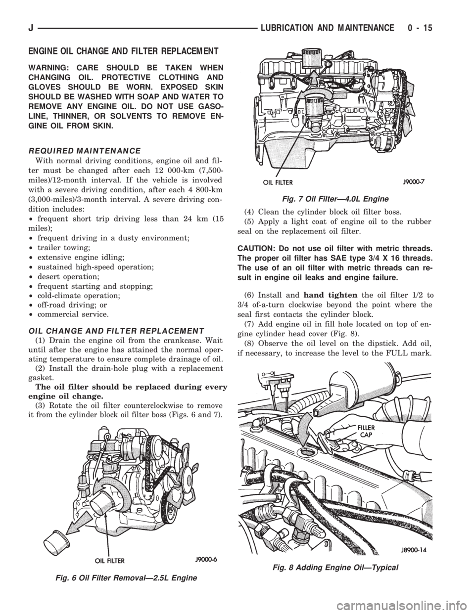
ENGINE OIL CHANGE AND FILTER REPLACEMENT
WARNING: CARE SHOULD BE TAKEN WHEN
CHANGING OIL. PROTECTIVE CLOTHING AND
GLOVES SHOULD BE WORN. EXPOSED SKIN
SHOULD BE WASHED WITH SOAP AND WATER TO
REMOVE ANY ENGINE OIL. DO NOT USE GASO-
LINE, THINNER, OR SOLVENTS TO REMOVE EN-
GINE OIL FROM SKIN.
REQUIRED MAINTENANCE
With normal driving conditions, engine oil and fil-
ter must be changed after each 12 000-km (7,500-
miles)/12-month interval. If the vehicle is involved
with a severe driving condition, after each 4 800-km
(3,000-miles)/3-month interval. A severe driving con-
dition includes:
²frequent short trip driving less than 24 km (15
miles);
²frequent driving in a dusty environment;
²trailer towing;
²extensive engine idling;
²sustained high-speed operation;
²desert operation;
²frequent starting and stopping;
²cold-climate operation;
²off-road driving; or
²commercial service.
OIL CHANGE AND FILTER REPLACEMENT
(1) Drain the engine oil from the crankcase. Wait
until after the engine has attained the normal oper-
ating temperature to ensure complete drainage of oil.
(2) Install the drain-hole plug with a replacement
gasket.
The oil filter should be replaced during every
engine oil change.
(3)
Rotate the oil filter counterclockwise to remove
it from the cylinder block oil filter boss (Figs. 6 and 7).
(4) Clean the cylinder block oil filter boss.
(5) Apply a light coat of engine oil to the rubber
seal on the replacement oil filter.
CAUTION: Do not use oil filter with metric threads.
The proper oil filter has SAE type 3/4 X 16 threads.
The use of an oil filter with metric threads can re-
sult in engine oil leaks and engine failure.
(6) Install andhand tightenthe oil filter 1/2 to
3/4 of-a-turn clockwise beyond the point where the
seal first contacts the cylinder block.
(7) Add engine oil in fill hole located on top of en-
gine cylinder head cover (Fig. 8).
(8) Observe the oil level on the dipstick. Add oil,
if necessary, to increase the level to the FULL mark.
Fig. 6 Oil Filter RemovalÐ2.5L Engine
Fig. 7 Oil FilterÐ4.0L Engine
Fig. 8 Adding Engine OilÐTypical
JLUBRICATION AND MAINTENANCE 0 - 15
Page 27 of 1784
If the transfer case ATF is warm, it is accept-
able for the fluid to drip out of the fill hole. If
the fluid gushes out of the fill hole, the level is
too high.
(3) If the level is low, raise it to the bottom edge of
the fill hole with MOPAR ATF PLUS type 7176 or
an equivalent MerconŸ/Dexron IIŸ ATF.
(4) Install the fill-hole plug. Tighten the plug with
47 NIm (35 ft. lbs.) torque.
(5) Remove the support and lower the vehicle.
FLUID CHANGE
When it becomes necessary to change the ATF in a
Jeepttransfer case, use the following procedure.
(1) Raise and support the vehicle.
(2) Remove the fill-hole plug from the transfer
case.
(3) Place an appropriate container under the trans-
fer case drain-hole plug.
(4) Remove the drain-hole plug and drain the ATF
from the transfer case into the container.
Care should be exercised when disposing used
ATF after it has been drained from a transfer
case.
CAUTION: Do not over-tighten the drain and fill-hole
plugs. Over-tightening can strip the hole threads
and/or crack the aluminum housing.
(5) Install the drain-hole plug in the transfer case.
Tighten the plug with 47 NIm (35 ft. lbs.) torque.
(6) Fill the transfer case to the bottom edge of the
fill hole with MOPAR ATF PLUS type 7176 (or an
equivalent MerconŸ/Dexron IIŸ ATF).
(7) Install the fill-hole plug in the transfer case.
Tighten the plug with 47 NIm (35 ft. lbs.) torque.
(8) Remove the support and lower the vehicle.
FRONT AND REAR AXLES
RECOMMENDED MAINTENANCE
The lubricant level in axle differential housings
should be determined at the same time as the engine
oil is changed and the oil filter is replaced. Add lu-
bricant as necessary.
In addition, with normal driving conditions, the
axle lubricant should be changed after each 48
000-km (30,000-miles). With severe driving condi-
tions, after each 29 000-km (12,000-miles).
LUBRICANT SPECIFICATIONS
For normal vehicle operation, use SAE 75W-90,
API Quality Grade GL-5 gear lubricant in all Jeept
front (4WD only) and rear axles. Vehicles equipped
with a Trac-Loc rear axle also require a friction mod-
ifier additive with the gear lubricant.
When involved in trailer towing applications
use SAE 80W-140, API Quality Grade GL-5 gearlubricant in the rear axle. XJ Vehicles equipped
with a class III trailer hitch require SAE
75W-140 synthetic gear lubricant in the rear
axle.
LUBRICANT LEVEL
Determine the axle differential housing lubricant
level according to the following procedure.
(1) Raise and support the vehicle.
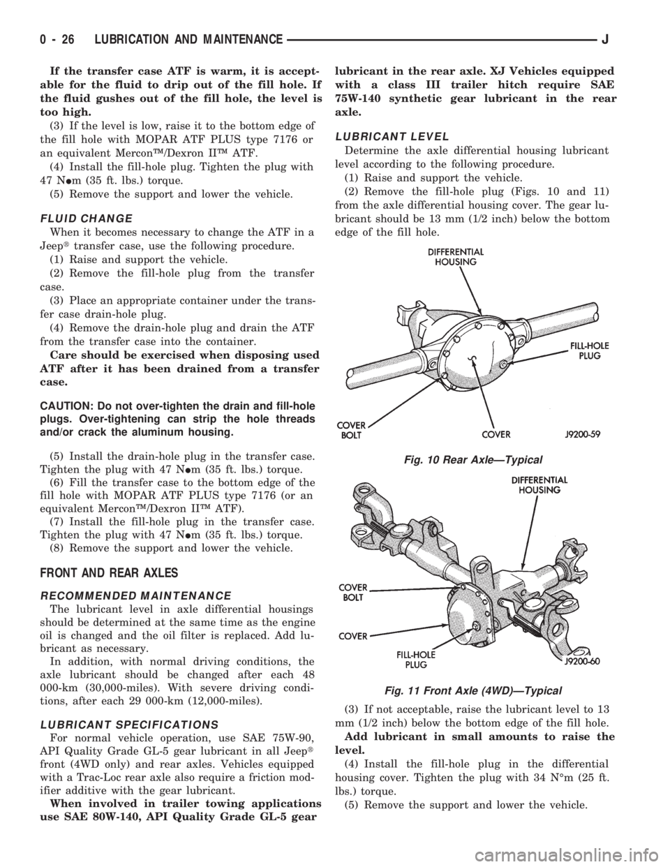
(2) Remove the fill-hole plug (Figs. 10 and 11)
from the axle differential housing cover. The gear lu-
bricant should be 13 mm (1/2 inch) below the bottom
edge of the fill hole.
(3) If not acceptable, raise the lubricant level to 13
mm (1/2 inch) below the bottom edge of the fill hole.
Add lubricant in small amounts to raise the
level.
(4) Install the fill-hole plug in the differential
housing cover. Tighten the plug with 34 NÉm (25 ft.
lbs.) torque.
(5) Remove the support and lower the vehicle.
Fig. 10 Rear AxleÐTypical
Fig. 11 Front Axle (4WD)ÐTypical
0 - 26 LUBRICATION AND MAINTENANCEJ
Page 53 of 1784
AXLE NOISE/VIBRATION DIAGNOSIS
INDEX
page page
Driveline Snap........................... 17
Gear and Bearing Noise................... 16
General Information....................... 16Low Speed Knock........................ 17
Vibration............................... 17
GENERAL INFORMATION
Axle bearing problem conditions are usually caused
by:
²Insufficient or incorrect lubricant
²Foreign matter/water contamination
²Incorrect bearing preload torque adjustment
²Incorrect backlash (to tight)
When serviced, the bearings must be cleaned thor-
oughly. They should be dried with lint-free shop tow-
els.Never dry bearings with compressed air.
This will overheat them and brinell the bearing
surfaces. This will result in noisy operation after
repair.
Axle gear problem conditions are usually the result
of:
²Insufficient lubrication
²Incorrect or contaminated lubricant
²Overloading (excessive engine torque) or exceeding
vehicle weight capacity
²Incorrect clearance or backlash adjustment
Insufficient lubrication is usually the result of a
housing cover leak. It can also be from worn axle
shaft or pinion gear seals. Check for cracks or porous
areas in the housing or tubes.
Using the wrong lubricant will cause overheating
and gear failure. Gear tooth cracking and bearing
spalling are indicators of this.
Axle component breakage is most often the result
of:
²Severe overloading
²Insufficient lubricant
²Incorrect lubricant
²Improperly tightened components
Overloading occurs when towing heavier than rec-
ommended loads. Component breakage can occur
when the wheels are spun excessively. Incorrect lu-
bricant quantity contributes to breakage. Loose dif-
ferential components can also cause breakage.
Incorrect bearing preload or gear backlash will not
result in component breakage. Mis-adjustment will
produce enough noise to cause service repair before a
failure occurs. If a mis-adjustment condition is not
corrected, component failure can result.
Excessive bearing preload may not be noisy. This
condition will cause high temperature which can re-
sult in bearing failure.
GEAR AND BEARING NOISE
GEAR NOISE
Axle gear noise can be caused by insufficient lubri-
cant. Incorrect backlash, tooth contact, or worn/dam-
aged gears can cause noise.
Gear noise usually happens at a specific speed
range. The range is 30 to 40 mph, or above 50 mph.
The noise can also occur during a specific type of
driving condition. These conditions are acceleration,
deceleration, coast, or constant load.
When road testing, accelerate the vehicle to the
speed range where the noise is the greatest. Shift
out-of-gear and coast through the peak-noise range.
If the noise stops or changes greatly, check for insuf-
ficient lubricant. Incorrect ring gear backlash, or
gear damage can cause noise changes.
Differential side and pinion gears can be checked
by turning the vehicle. They usually do not cause
noise in straight-ahead driving. These gears are
loaded during vehicle turns. If noise does occur dur-
ing vehicle turns, the side or pinion gears could be
worn or damaged. A worn pinion gear mate shaft can
also cause a snapping or a knocking noise.
BEARING NOISE
The axle shaft, differential and pinion gear bear-
ings can all produce noise when worn or damaged.
Bearing noise can be either a whining, or a growling
sound.
Pinion gear bearings have a constant-pitch noise.
This noise changes only with vehicle speed. Pinion
bearing noise will be higher because it rotates at a
faster rate. Drive the vehicle and load the differen-
tial. If bearing noise occurs the pinion rear bearing is
the source of the noise. If the bearing noise is heard
during a coast, front bearing is the source.
Worn, damaged differential bearings usually pro-
duce a low pitch noise. Differential bearing noise is
similar to pinion bearing. The pitch of differential
bearing noise is also constant and varies only with
vehicle speed.
Axle shaft bearings produce noise and vibration
when worn or damaged. The noise generally changes
when the bearings are loaded. Road test the vehicle.
Turn the vehicle sharply to the left and to the right.
This will load the bearings and change the noise
2 - 16 FRONT SUSPENSION AND AXLEJ
Page 238 of 1784
ERASING TROUBLE CODES
After the problem has been repaired, the DRB scan
tool must be used to erase a DTC. Refer to the ap-
propriate Powertrain Diagnostic Procedures service
manual for operation of the DRB scan tool.
DRB SCAN TOOL
For operation of the DRB scan tool, refer to the ap-
propriate Powertrain Diagnostic Procedures service
manual.
PRELIMINARY CHECKS
ENGINE COOLING SYSTEM OVERHEATING
Establish what driving conditions caused the com-
plaint. Abnormal loads on the cooling system such as
the following may be the cause.
1. PROLONGED IDLE, VERY HIGH AMBI-
ENT TEMPERATURE, SLIGHT TAIL WIND AT
IDLE, SLOW TRAFFIC, TRAFFIC JAMS, HIGH
SPEED, OR STEEP GRADES:
Driving techniques that avoid overheating are:
²Idle with A/C off when temperature gauge is at
end of normal range.
²Increasing engine speed for more air flow is recom-
mended.2. TRAILER TOWING:
Consult Trailer Towing section of owners manual.
Do not exceed limits.
3. AIR CONDITIONING; ADD-ON OR AFTER
MARKET:
A maximum cooling package should have been or-
dered with vehicle if add-on or after market A/C is
installed. If not, maximum cooling system compo-
nents should be installed for model involved per
manufacturer's specifications.
4. RECENT SERVICE OR ACCIDENT RE-
PAIR:
Determine if any recent service has been performed
on vehicle that may effect cooling system. This may
be:
²Engine adjustments (incorrect timing)
²Slipping engine accessory drive belt(s)
²Brakes (possibly dragging)
²Changed parts (incorrect water pump rotating in
wrong direction)
²Reconditioned radiator or cooling system refilling
(possibly under-filled or air trapped in system).
If investigation reveals none of the above as a
cause for engine overheating complaint, refer to fol-
lowing Symptom and Action chart.
JCOOLING SYSTEM 7 - 5
Page 1543 of 1784
The reinforcement bracket is held on the
frame rail with two blind rivets.
(2) Remove the bracket and tow hook from frame
rail.
INSTALLATION
(1) Position bracket and tow hook on the frame
rail.
(2) Install bolts that attach tow hook bracket to
frame rail and reinforcement bracket. Tighten bolts
to 75 Nzm (55 ft-lbs) torque.
TRAILER HITCHES
CLASS III HITCHÐXJ VEHICLES
A class III weight-distributing/equalizer type hitch
can be used to tow a trailer:
²having a maximum gross weight of 5,000 lbs/2250
kg, and
²having a maximum tongue weight of 750 lbs/332
kg).
The following vehicle basic equipment is required
for class III trailer towing:
²P205/75R15 or larger tires;
²full size spare tire;
²trailer sway control;
²trailer tow wire harness and connector;
²heavy duty turn signal flasher element;
²heavy duty axle (with synthetic lubricant);²heavy duty cooling system;
²heavy duty generator/battery;
²auxiliary automatic transmission fluid cooler; and
²I-6, 4.0L engine.
Wide-angle type door mirrors are recommended but
not required.
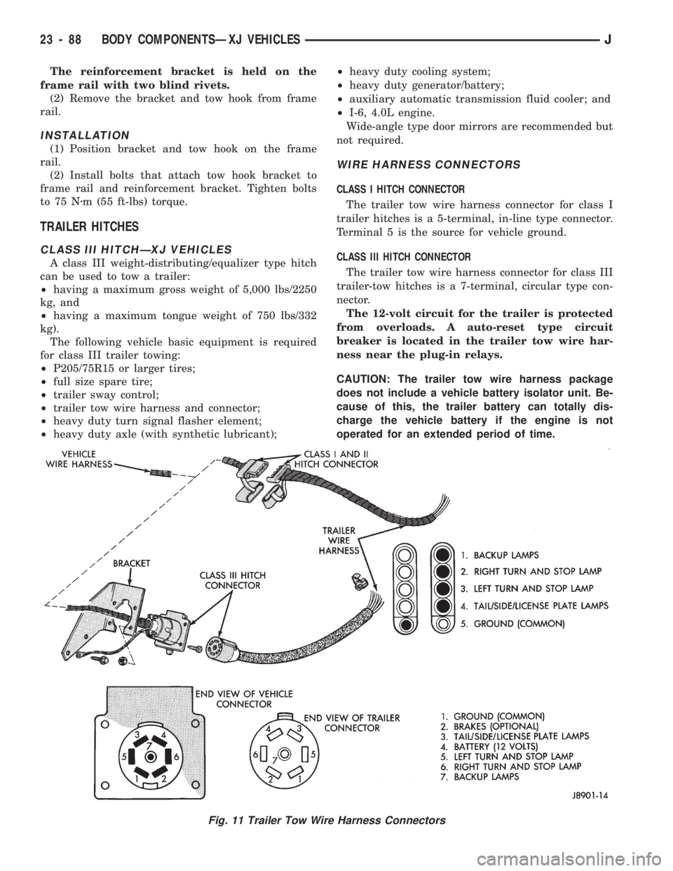
WIRE HARNESS CONNECTORS
CLASS I HITCH CONNECTOR
The trailer tow wire harness connector for class I
trailer hitches is a 5-terminal, in-line type connector.
Terminal 5 is the source for vehicle ground.
CLASS III HITCH CONNECTOR
The trailer tow wire harness connector for class III
trailer-tow hitches is a 7-terminal, circular type con-
nector.
The 12-volt circuit for the trailer is protected
from overloads. A auto-reset type circuit
breaker is located in the trailer tow wire har-
ness near the plug-in relays.
CAUTION: The trailer tow wire harness package
does not include a vehicle battery isolator unit. Be-
cause of this, the trailer battery can totally dis-
charge the vehicle battery if the engine is not
operated for an extended period of time.
Fig. 11 Trailer Tow Wire Harness Connectors
23 - 88 BODY COMPONENTSÐXJ VEHICLESJ
Page 1544 of 1784
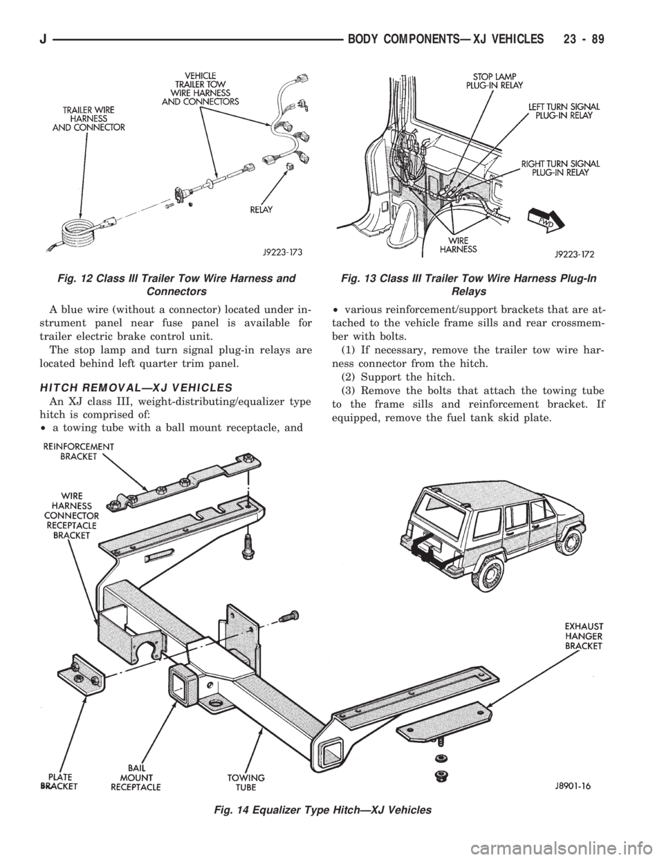
A blue wire (without a connector) located under in-
strument panel near fuse panel is available for
trailer electric brake control unit.
The stop lamp and turn signal plug-in relays are
located behind left quarter trim panel.
HITCH REMOVALÐXJ VEHICLES
An XJ class III, weight-distributing/equalizer type
hitch is comprised of:
²a towing tube with a ball mount receptacle, and²various reinforcement/support brackets that are at-
tached to the vehicle frame sills and rear crossmem-
ber with bolts.
(1) If necessary, remove the trailer tow wire har-
ness connector from the hitch.
(2) Support the hitch.
(3) Remove the bolts that attach the towing tube
to the frame sills and reinforcement bracket. If
equipped, remove the fuel tank skid plate.
Fig. 14 Equalizer Type HitchÐXJ Vehicles
Fig. 12 Class III Trailer Tow Wire Harness and
ConnectorsFig. 13 Class III Trailer Tow Wire Harness Plug-In
Relays
JBODY COMPONENTSÐXJ VEHICLES 23 - 89
Page 1545 of 1784
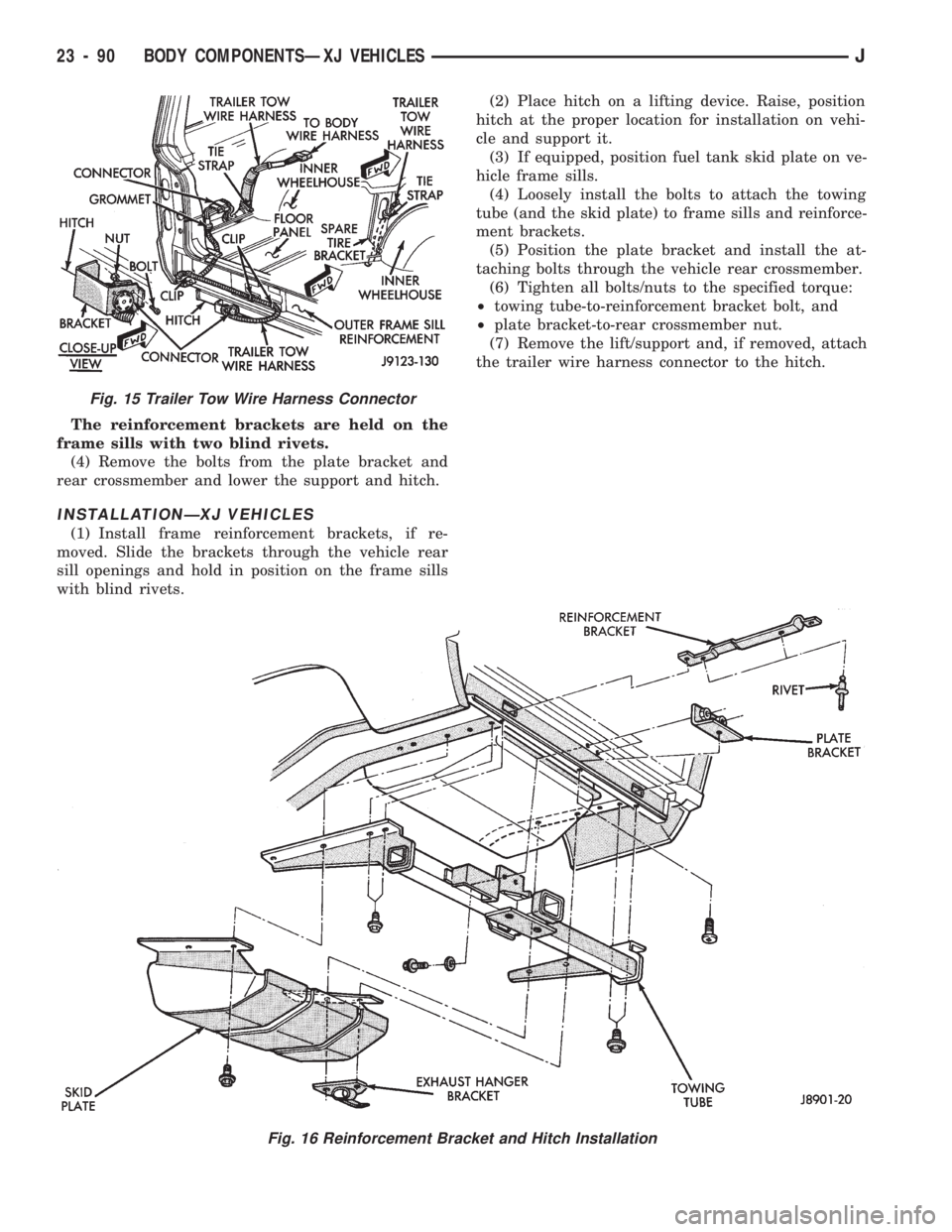
The reinforcement brackets are held on the
frame sills with two blind rivets.
(4) Remove the bolts from the plate bracket and
rear crossmember and lower the support and hitch.
INSTALLATIONÐXJ VEHICLES
(1) Install frame reinforcement brackets, if re-
moved. Slide the brackets through the vehicle rear
sill openings and hold in position on the frame sills
with blind rivets.(2) Place hitch on a lifting device. Raise, position
hitch at the proper location for installation on vehi-
cle and support it.
(3) If equipped, position fuel tank skid plate on ve-
hicle frame sills.
(4) Loosely install the bolts to attach the towing
tube (and the skid plate) to frame sills and reinforce-
ment brackets.
(5) Position the plate bracket and install the at-
taching bolts through the vehicle rear crossmember.
(6) Tighten all bolts/nuts to the specified torque:
²towing tube-to-reinforcement bracket bolt, and
²plate bracket-to-rear crossmember nut.
(7) Remove the lift/support and, if removed, attach
the trailer wire harness connector to the hitch.
Fig. 15 Trailer Tow Wire Harness Connector
Fig. 16 Reinforcement Bracket and Hitch Installation
23 - 90 BODY COMPONENTSÐXJ VEHICLESJ
Page 1755 of 1784
GRILLE OPENING PANEL (GOP), GRILLE.....23-3
GRILLEÐXJ VEHICLES, AIR EXHAUST.....23-30
GROUND, POWER.....................14-22
GROUP INDEX; ELECTRICAL..............8A-1
GUARD, BRUSH........................23-3
GUARD/EDGE PROTECTOR STRIP, DOOR
EDGE..............................23-61
GUIDES AND CHARTS, DIAGNOSIS........21-76
HALF METAL DOOR MIRROR (EXTERNAL) . . 23-158
HALF-METAL DOOR LATCH STRIKER......23-175
HALF-METAL SOFT TOP DOOR..........23-173
HAND DRIVE, BATTERY CLASSIFICATIONS
AND RATINGSÐLEFT.................8B-10
HAND DRIVE, BATTERY CLASSIFICATIONS
AND RATINGSÐRIGHT................8B-10
HAND DRIVE, BATTERY REPLACEMENTÐ
LEFT...............................8B-1
HAND DRIVE, BATTERY REPLACEMENTÐ
RIGHT..............................8B-2
HAND DRIVE, BELT SERVICEÐEXCEPT
RIGHT..............................7-34
HAND DRIVE, BELT SERVICEÐWITH
RIGHT..............................7-35
HAND DRIVE, DRIVERS DOOR POWER
LOCK SWITCHÐ2-DOOR LEFT...........8P-2
HAND DRIVE, DRIVERS DOOR POWER
LOCK SWITCHÐ2-DOOR RIGHT..........8P-3
HAND DRIVE, DRIVERS DOOR POWER
WINDOW SWITCHÐ2-DOOR LEFT........8S-6
HAND DRIVE, DRIVERS DOOR POWER
WINDOW SWITCHÐ2-DOOR RIGHT......8S-7
HAND DRIVE, GENERATOR
REPLACEMENTÐLEFT.................8B-7
HAND DRIVE, GENERATOR
REPLACEMENTÐRIGHT................8B-9
HAND DRIVE (RHD), BELT TENSIONÐ
EXCEPT RIGHT.......................7-33
HAND DRIVE (RHD), BELT TENSIONÐ
RIGHT..............................7-34
HAND DRIVE VEHICLES, RIGHT............23-1
HAND DRIVE, WASHER PUMP
REPLACEMENTÐLEFT.................8K-2
HAND DRIVE, WASHER PUMP
REPLACEMENTÐRIGHT................8K-3
HANDLE, DOOR EXTERNAL..............23-55
HANDLE, FULL-METAL DOOR ASSIST.....23-175
HANDLE, FULL-METAL DOOR LATCH
EXTERNAL RELEASE.................23-178
HANDLE, FULL-METAL DOOR LATCH
INSIDE RELEASE AND LOCK...........23-175
HANDLE, FULL-METAL DOOR WINDOW
GLASS REGULATOR.................23-175
HANDLE, TAILGATE LATCH AND
RELEASE..........................23-160
HANDLEÐXJ VEHICLES, ASSIST.........23-118
HANGER BRACKET, MUFFLER/TAILPIPE.....13-16
HARD TOP DOME/CARGO LAMP BULB
REPLACEMENTÐYJ VEHICLES..........8L-20
HARD TOP LIFTGATE GLASS............23-162
HARD TOP QUARTER WINDOW GLASS....23-188
HARD TOP REPAIR....................23-165
HARD TOP ROOF VENT................23-165
HARD TOP SERVICE...................23-164
HARD TOP SERVICE INFORMATION.......23-164
HAZARD LAMPSÐXJ....................8J-1
HAZARD LAMPSÐYJ....................8J-2
HCU DIAGNOSIS........................5-4
HCU INSTALLATIONÐXJ.................5-54
HCU INSTALLATIONÐYJ.................5-54
HCU PUMP AND PEDAL TRAVEL
SENSOR OPERATION...................5-44
HCU REMOVALÐXJ.....................5-53
HCU REMOVALÐYJ.....................5-54
HCU SOLENOID VALVE OPERATION.........5-43
HEAD COVER, ENGINE CYLINDER......9-18,9-59
HEAD, ENGINE CYLINDER............9-19,9-60
HEAD GASKET FAILURE DIAGNOSIS,
ENGINE CYLINDER.....................9-5
HEADLAMP BEAM ADJUSTMENT...........8L-3
HEADLAMP BULB REPLACEMENT
..........8L-3
HEADLAMP DELAY FUNCTION TROUBLE
DIAGNOSISÐXJ VEHICLES
.............8L-16
HEADLAMP DELAY MODULE
REPLACEMENTÐXJ VEHICLES
..........8L-16
HEADLAMP DELAY MODULEÐXJ
VEHICLES, SENTINEL
.................8L-15HEADLAMP DIMMER SWITCH
REPLACEMENT.......................8L-6
HEADLAMP SWITCH REPLACEMENT........8L-4
HEADLAMP SWITCH/ILLUMINATION
RHEOSTAT..........................8E-21
HEADLAMP TROUBLE DIAGNOSISÐ
XJ VEHICLES.........................8L-1
HEADLAMP TROUBLE DIAGNOSISÐYJ
VEHICLES...........................8L-2
HEADLAMPS...........................0-35
HEADLINER.........................23-121
HEAT SHIELDS........................14-12
HEAT SHIELDS, EXHAUST................11-1
HEAT SHIELDS, MUFFLER AND TAILPIPE . . . 13-17
HEATER AND A/C CONTROL PANEL
REPLACEMENT......................24-26
HEATER CONTROL CABLE REPLACEMENT . . . 24-30
HEATER CONTROL PANEL REPLACEMENT . . . 24-39
HEATER CORE........................24-28
HEATER CORE AND HOUSING............24-40
HEATER CORE HOUSING REPLACEMENT . . . 24-29
HEATER, ENGINE BLOCK.................7-37
HEATER/DEFROSTER OPERATION.........24-37
HEATER/DEFROSTER/INSTRUMENT
PANEL OUTLET DOOR VACUUM MOTOR
REPLACEMENT......................24-30
HEATING ELEMENT TEST, OXYGEN
SENSOR (O2S)......................14-45
HEATING SCHEMATIC...................24-24
HEATING SYSTEM DIAGNOSIS............24-11
HEATING SYSTEMÐYJ VEHICLES.........24-14
HIGH LINE CLUSTER...................8E-12
HIGH MOUNTED STOP LAMP (CHMSL)Ð
XJ, CENTER.........................8L-10
HIGH MOUNTED STOP LAMP (CHMSL)Ð
YJ, CENTER.........................8L-11
HINGE, LIFTGATE......................23-67
HINGE REPLACEMENT, HOOD.............23-9
HINGE, TAILGATE.....................23-159
HINGE/HINGE PIN REPLACEMENT, DOOR . . . 23-58
HINGES, FULL-METAL DOOR............23-179
HITCHES, TRAILER.....................23-88
HOISTING AND TOWING, JUMP
STARTING,............................0-7
HOLDDOWN AND FLOOR BRACKETSÐ
XJ VEHICLES, SPARE TIRE/WHEEL......23-128
HONING CYLINDER BORES................9-2
HOOD..........................23-6,23-137
HOOD ADJUSTMENT....................23-9
HOOD ALIGNMENT....................23-138
HOOD HINGE REPLACEMENT..............23-9
HOOD INSULATOR PANEL..............23-138
HOOD LATCH REPLACEMENT............23-10
HOOD LATCH STRIKER REPLACEMENT.....23-10
HOOD SAFETY LATCH.................23-139
HOOKÐXJ VEHICLES, REAR TOW.........23-87
HOOKS, FRONT TOW....................13-5
HOOKS, TOW.........................13-14
HORN PAD REPLACEMENT, HORN SWITCH . . . 8G-3
HORN SWITCH (HORN PAD)
REPLACEMENT.......................8G-3
HOSE REPLACEMENT, PRESSURE AND
RETURN............................19-9
HOSE ROUTING SCHEMATICS,
VACUUM............................25-1
HOSE SPLASH SHIELDÐXJ VEHICLES,
FUEL FILLER........................23-86
HOSES, BRAKE BLEEDINGÐBRAKE FLUID
AND LEVELÐBRAKELINES..............5-13
HOSES, BRAKELINES....................5-15
HOSES, COOLING SYSTEM...............7-26
HOSES/TUBING, RUBBER AND PLASTIC.....0-28
HOUSING, AIR CLEANER; EMISSION
CONTROL SYSTEMS...................25-8
HOUSING, AIR CLEANER; FUEL SYSTEM....14-54
HOUSING AND PARK LOCK COMPONENT
OVERHAUL, ADAPTER................21-120
HOUSING END PLUG...................19-26
HOUSING, EVAPORATOR................24-42
HOUSING, EVAPORATOR/BLOWER.........24-33
HOUSING, HEATER CORE................24-40
HOUSING LEAK DIAGNOSIS, CONVERTER
. . . 21-73
HOUSING, LIFTGATE LICENSE PLATE
LAMP
..............................23-72
HOUSING REPLACEMENT, CLUTCH
.........6-11
HOUSING REPLACEMENT, HEATER CORE
. . . 24-29HOUSING SEAL REPLACEMENT,
ADAPTER..........................21-182
HOUSINGS, INSTRUMENT CLUSTER
AND GAUGE........................23-190
HUB BEARING AND AXLE SHAFT...........2-24
HYDRAULIC CLUTCH....................0-22
HYDRAULIC COMPONENTS................5-1
HYDRAULIC CONTROL UNIT (HCU).........5-39
HYDRAULIC FLOW DURING FULL
THROTTLE 3-2 DOWNSHIFT............21-92
HYDRAULIC FLOW DURING PART
THROTTLE 3-2 DOWNSHIFT............21-91
HYDRAULIC FLOW IN D RANGE FIRST
GEAR..............................21-87
HYDRAULIC FLOW IN D RANGE SECOND
GEAR..............................21-88
HYDRAULIC FLOW IN D RANGE THIRD
GEAR..............................21-89
HYDRAULIC FLOW IN MANUAL FIRST
GEAR (1) POSITION..................21-94
HYDRAULIC FLOW IN MANUAL SECOND
(2) RANGE..........................21-93
HYDRAULIC FLOW IN PARK AND NEUTRAL . . . 21-86
HYDRAULIC FLOW IN REVERSE..........21-95
HYDRAULIC FLOW IN THIRD GEAR
(CONVERTER CLUTCH ENGAGED)........21-90
HYDRAULIC LINKAGE INSTALLATION,
CLUTCH.............................6-12
HYDRAULIC LINKAGE REMOVAL,
CLUTCH.............................6-11
HYDRAULIC PRESSURE TEST......21-71,21-168
HYDRAULIC SYSTEM..................21-160
HYDRAULIC TAPPETS...............9-24,9-65
HYDROMETER TEST....................8A-3
IDENTIFICATION, AW-4 VALVE AND
SPRING...........................21-330
IDENTIFICATION, CIRCUIT................8W-2
IDENTIFICATION, COMPONENT............8W-2
IDENTIFICATION, ENGINE AND
TRANSMISSION/TRANSFER CASE.....INTRO.-3
IDENTIFICATION, MAJOR COMPONENT . . INTRO.-3
IDENTIFICATION NUMBER (VIN)
DECODING, VEHICLE...............INTRO.-2
IDENTIFICATION NUMBER (VIN) PLATE,
VEHICLE.........................INTRO.-1
IDENTIFICATION, TRANSFER CASE
. 21-273,21-293
IDENTIFICATION, TRANSMISSION
.....21-1,21-32,
21-66,21-157
IDENTIFICATION, WIRE CODE
.............8W-2
IDENTIFICATION, WIRING AND
COMPONENT
.......................8W-13
IDLE AIR CONTROL (IAC) MOTOR
.........14-56
IDLE AIR CONTROL (IAC) MOTORÐPCM
OUTPUT
............................14-25
IDLE AIR CONTROL MOTOR TEST
.........14-46
IDLE SWITCHÐPCM INPUT, EXTENDED
....14-21
IDLE SWITCH TEST, EXTENDED
...........14-45
IGNITION CABLES, DISTRIBUTOR CAP
AND ROTOR
.........................0-18
IGNITION CIRCUIT SENSEÐPCM INPUT
....14-21
IGNITION COIL; FUEL SYSTEM
...........14-57
IGNITION COIL; IGNITION SYSTEMS
. . 8D-4,8D-11,
8D-26
IGNITION COILÐPCM OUTPUT
...........14-26
IGNITION COIL RESISTANCE
.............8D-11
IGNITION KEY WARNING SWITCH
REPLACEMENT
.......................8U-4
IGNITION OFF DRAW (IOD) DIAGNOSIS
.....8A-8
IGNITION SECONDARY CIRCUIT
DIAGNOSIS
.........................8D-12
IGNITION SWITCH; BRAKES
...............5-42
IGNITION SWITCH CONTINUITY TESTS
.....8D-31
IGNITION SWITCH; IGNITION SYSTEMS
....8D-30
IGNITION SWITCH INSTALLATION/
ADJUSTMENT
.......................8D-31
IGNITION SWITCH REMOVAL
............8D-30
IGNITION SWITCH TESTING
.............8D-30
IGNITION TIMING
......................8D-14
IGNITION WIRING, SECONDARY
...........8W-1
ILLUMINATED ENTRY SYSTEM SERVICE
INFORMATION
.......................8L-20
ILLUMINATED ENTRY SYSTEM TROUBLE
DIAGNOSIS
....................8L-21,8L-22
JINDEX11
Description Group-Page Description Group-Page Description Group-Page