1994 JEEP CHEROKEE open hood
[x] Cancel search: open hoodPage 1458 of 1784
EXTERIOR COMPONENTS
BRUSH GUARD
REMOVAL
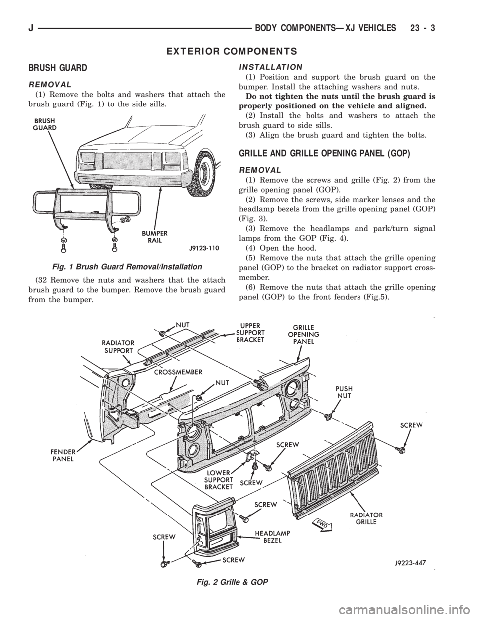
(1) Remove the bolts and washers that attach the
brush guard (Fig. 1) to the side sills.
(32 Remove the nuts and washers that the attach
brush guard to the bumper. Remove the brush guard
from the bumper.
INSTALLATION
(1) Position and support the brush guard on the
bumper. Install the attaching washers and nuts.
Do not tighten the nuts until the brush guard is
properly positioned on the vehicle and aligned.
(2) Install the bolts and washers to attach the
brush guard to side sills.
(3) Align the brush guard and tighten the bolts.
GRILLE AND GRILLE OPENING PANEL (GOP)
REMOVAL
(1) Remove the screws and grille (Fig. 2) from the
grille opening panel (GOP).
(2) Remove the screws, side marker lenses and the
headlamp bezels from the grille opening panel (GOP)
(Fig. 3).
(3) Remove the headlamps and park/turn signal
lamps from the GOP (Fig. 4).
(4) Open the hood.
(5) Remove the nuts that attach the grille opening
panel (GOP) to the bracket on radiator support cross-
member.
(6) Remove the nuts that attach the grille opening
panel (GOP) to the front fenders (Fig.5).
Fig. 2 Grille & GOP
Fig. 1 Brush Guard Removal/Installation
JBODY COMPONENTSÐXJ VEHICLES 23 - 3
Page 1461 of 1784
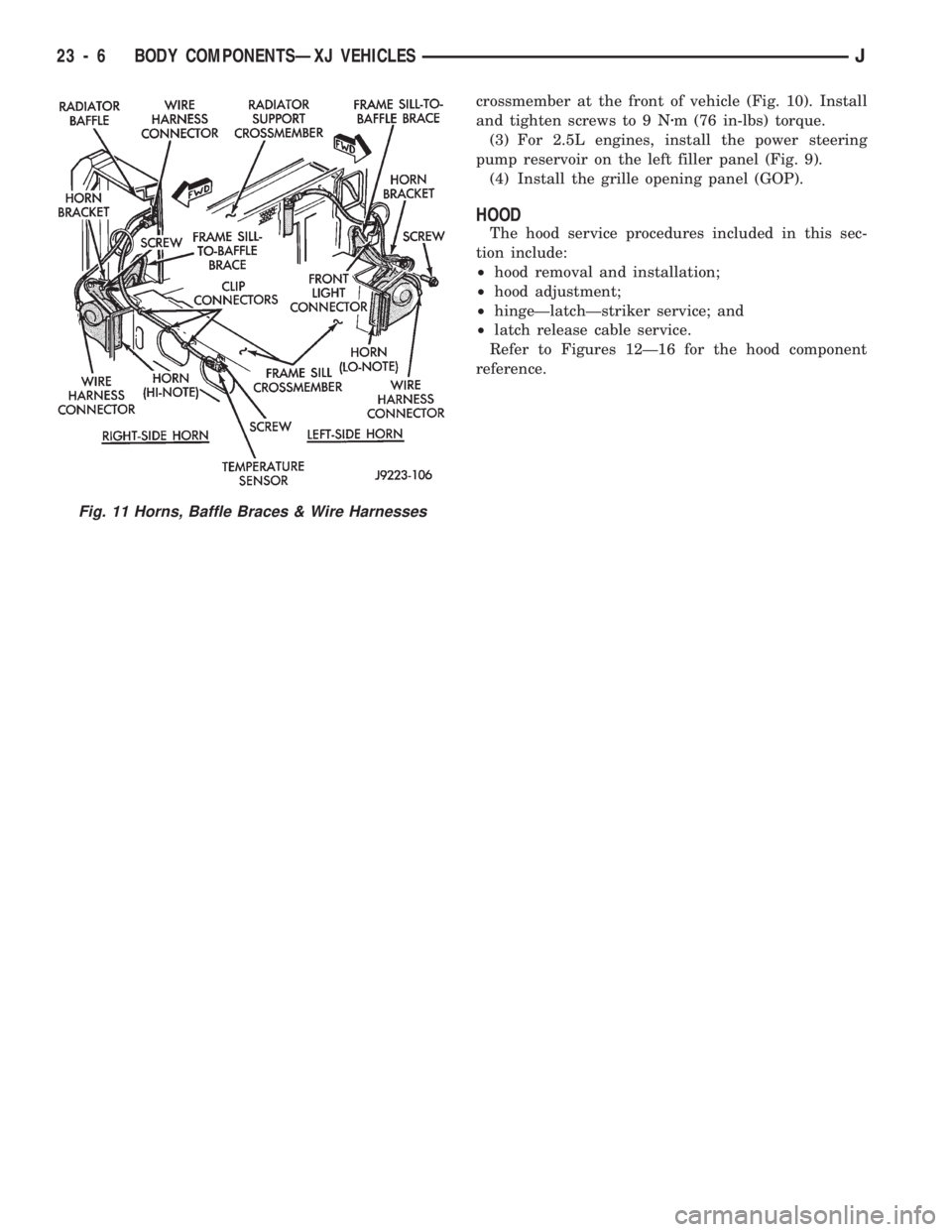
crossmember at the front of vehicle (Fig. 10). Install
and tighten screws to 9 Nzm (76 in-lbs) torque.
(3) For 2.5L engines, install the power steering
pump reservoir on the left filler panel (Fig. 9).
(4) Install the grille opening panel (GOP).
HOOD
The hood service procedures included in this sec-
tion include:
²hood removal and installation;
²hood adjustment;
²hingeÐlatchÐstriker service; and
²latch release cable service.
Refer to Figures 12Ð16 for the hood component
reference.
Fig. 11 Horns, Baffle Braces & Wire Harnesses
23 - 6 BODY COMPONENTSÐXJ VEHICLESJ
Page 1465 of 1784
(2) Install the hinge nuts on the studs. Tighten the
restraint cable nut to 4 Nzm (38 in-lbs) torque.
Tighten the remaining nuts to 9 Nzm (77 in-lbs)
torque.
If a replacement hinge seal is being installed,
position it around the hinge arm, force it
against the hinge base.
(3) Position the hinge seal around the hinge arm
and on hinge base.
(4) Install the hood.
(5) Adjust the hood as necessary.
HOOD LATCH REPLACEMENT
REMOVAL
(1) Remove the screw that attaches the latch to the
hood inner panel (Fig. 15).
(2) Disconnect the latch from the hood and latch
connecting rod. Remove the latch from the hood.
INSTALLATION
(1) Connect the latch to the latch connecting rod
and position it on the hood inner panel.
(2) Install the screw that attaches the latch to the
hood inner panel.
(3) Tighten the screw to 9 Nzm (77 in-lbs) torque.
(4) Test the operation of the latch release cable and
latch.
HOOD LATCH STRIKER REPLACEMENT
REMOVE
(1) Remove the grille opening panel (GOP).
(2) Remove the screws that attach the striker to
the radiator baffle (Fig. 19).
(3) Remove the striker and shims from the baffle.
INSTALLATION
(1) Position the shims and striker on the radiator
baffle and install the screws.
(2) Tighten the screws to 21 Nzm (15 ft-lbs) torque.
(3) Test the striker/hood alignment by opening and
closing the hood several times. Adjust the striker, if
necessary.
LATCH RELEASE CABLE REPLACEMENT
REMOVAL
(1) Drill out the bellcrank to hood rivet heads and
remove the rivets (Fig. 14).
(2) Disconnect the bellcrank from the latch rod and
the latch release cable. Remove the bellcrank from
the hood.
(3) Disconnect the latch release cable from the
clips on the hood.
(4) Remove the left cowl side trim panel.
(5) Remove the cable bracket screws from the cowl
side panel.(6) Pull the cable through the dash panel and re-
move it from under the instrument panel.
INSTALLATION
(1) Insert the replacement cable end through the
hole in the dash panel into the engine compartment.
(2) Pull the cable forward and seat the grommet in
the dash panel.
(3) Position the cable bracket on the cowl side
panel and install the screws. Tighten the screws to
13 Nzm (111 in-lbs) torque.
(4) Install the left cowl side trim panel.
(5) Connect the cable and latch rod to the
bellcrank (Fig. 14).
(6) Position the bellcrank on the hood and install
the rivets.
(7) Attach the cable to the clips.
(8) Test release the cable for proper operation.
SAFETY LATCH STRIKER REPLACEMENT
REMOVAL
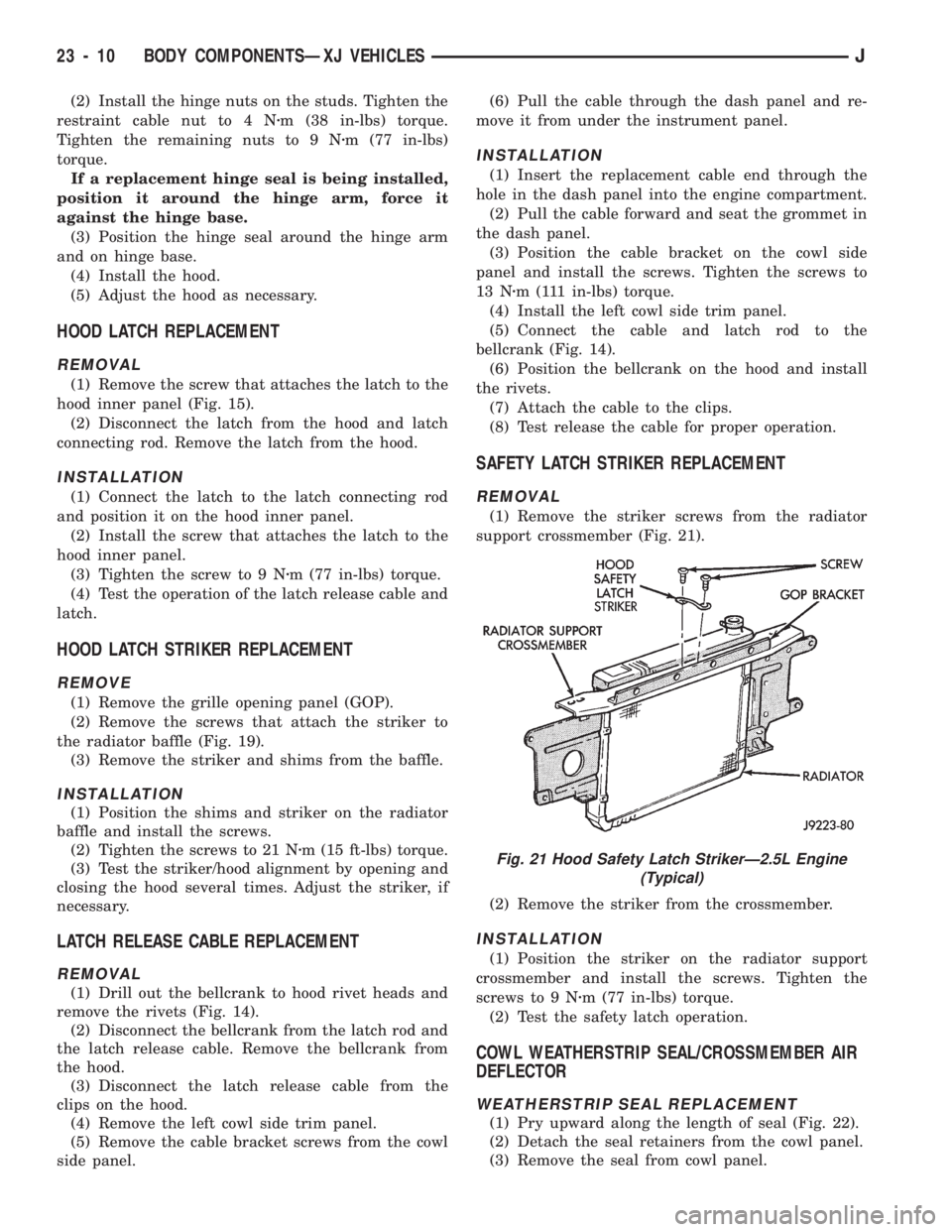
(1) Remove the striker screws from the radiator
support crossmember (Fig. 21).
(2) Remove the striker from the crossmember.
INSTALLATION
(1) Position the striker on the radiator support
crossmember and install the screws. Tighten the
screws to 9 Nzm (77 in-lbs) torque.
(2) Test the safety latch operation.
COWL WEATHERSTRIP SEAL/CROSSMEMBER AIR
DEFLECTOR
WEATHERSTRIP SEAL REPLACEMENT
(1) Pry upward along the length of seal (Fig. 22).
(2) Detach the seal retainers from the cowl panel.
(3) Remove the seal from cowl panel.
Fig. 21 Hood Safety Latch StrikerÐ2.5L Engine
(Typical)
23 - 10 BODY COMPONENTSÐXJ VEHICLESJ
Page 1471 of 1784
flare to the fender outer panel;
²remove the rivets that attach the flare to the air
deflector;
²remove the retainers that attach the fender liner
to the fender inner panel;
²remove the nuts that attach the fender liner to the
fender outer panel and flare retainers;
²remove the fender liner from between the fender
panels;
²remove the push-nuts that attach the retainers to
the fender outer panel; and
²remove the retainers and flare from the fender
outer panel.
(7) Remove the grille opening panel (GOP).
(8) Remove the air deflector.
(9) Remove the rocker panel moulding from the
fender.(10) Remove all the fender braces (Fig. 49).
(11) Remove the fender lower screws (Fig. 49).
(12) Remove the fender top, front and the rear
screws. Remove the fender from the inner fender
panel (Fig. 49).INSTALLATION
(1) Position the fender on the inner fender panel.
(2) Install all of the fender screws finger-tight.
(3) Install the fender braces.
(4) Align the fender with the body panels and
tighten the fender screws to 8.5 Nzm (76 in-lbs)
torque.
(5) Install the grille opening panel (GOP).
(6) Install the air deflector.
(7) Install the fender flare and retainers (Fig. 50).
Then install the fender liner.
²position the retainers and the flare on the fender;
²install the push-nuts to attach the retainers to the
fender;
²position the fender liner between the fender and
fender inner panel (Fig. 51);
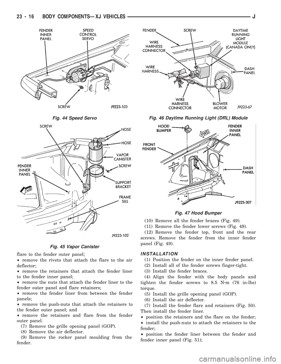
Fig. 44 Speed Servo
Fig. 45 Vapor Canister
Fig. 46 Daytime Running Light (DRL) Module
Fig. 47 Hood Bumper
23 - 16 BODY COMPONENTSÐXJ VEHICLESJ
Page 1656 of 1784
PAINT APPLICATION
INDEX
page page
Accent Paint........................... 202
Base/Color Coat........................ 201
Basecoat/Clearcoat...................... 202
Body Undercoat......................... 203
Buffing and Polishing..................... 203
Exterior Body Colors..................... 204Paint Repair on Galvanized Metals.......... 202
Plastic Components...................... 203
Primer................................ 201
Stone Chip Protection.................... 201
Surface Preparation...................... 201
SURFACE PREPARATION
Proper surface preparation is the key to top-quality
body panel refinishing. The bare metal must be
cleaned, de-greased, de-waxed and treated with phos-
phate.
Always clean the panel surface with a wax and
grease removal solution, and then wipe the surface
with a tack rag before applying primer or paint.
Cleaning will also remove any residual silicone from
the painted surface.
Body putty that is procured from a major supplier
is highly recommended. If a synthetic body filler is to
be used, it should also be a quality product.
STONE CHIP PROTECTION
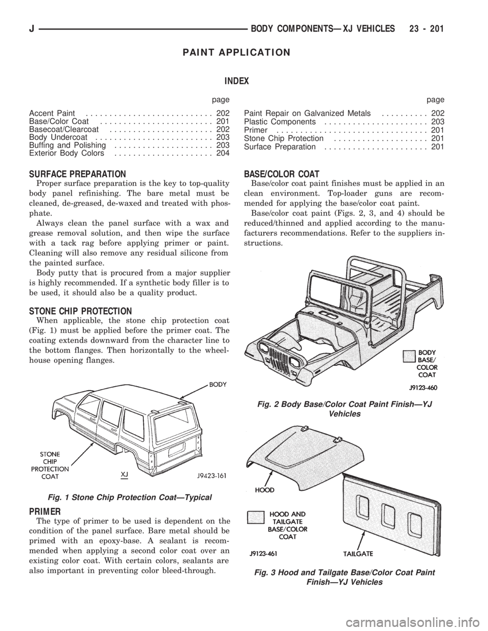
When applicable, the stone chip protection coat
(Fig. 1) must be applied before the primer coat. The
coating extends downward from the character line to
the bottom flanges. Then horizontally to the wheel-
house opening flanges.
PRIMER
The type of primer to be used is dependent on the
condition of the panel surface. Bare metal should be
primed with an epoxy-base. A sealant is recom-
mended when applying a second color coat over an
existing color coat. With certain colors, sealants are
also important in preventing color bleed-through.
BASE/COLOR COAT
Base/color coat paint finishes must be applied in an
clean environment. Top-loader guns are recom-
mended for applying the base/color coat paint.
Base/color coat paint (Figs. 2, 3, and 4) should be
reduced/thinned and applied according to the manu-
facturers recommendations. Refer to the suppliers in-
structions.
Fig. 2 Body Base/Color Coat Paint FinishÐYJ
Vehicles
Fig. 3 Hood and Tailgate Base/Color Coat Paint
FinishÐYJ Vehicles
Fig. 1 Stone Chip Protection CoatÐTypical
JBODY COMPONENTSÐXJ VEHICLES 23 - 201
Page 1657 of 1784
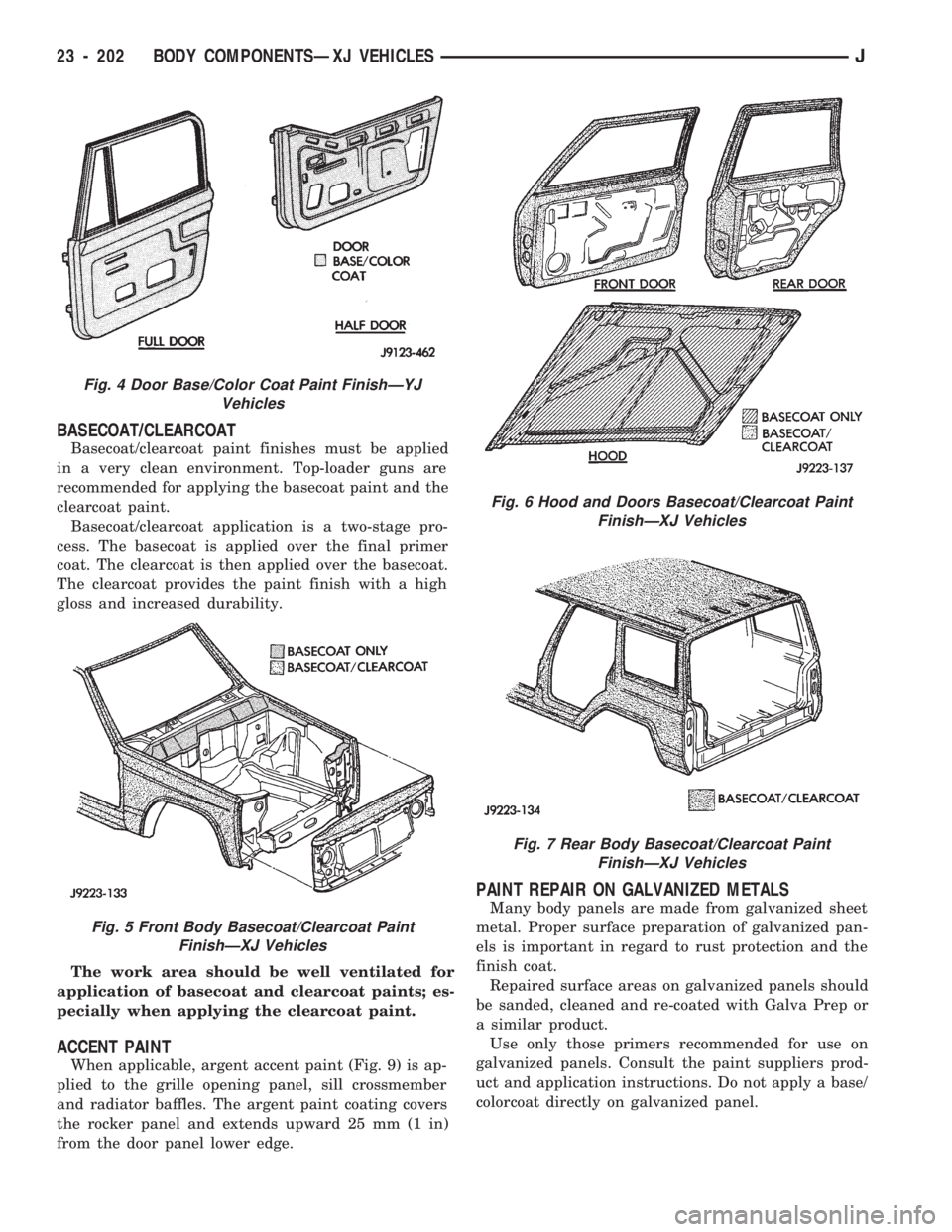
BASECOAT/CLEARCOAT
Basecoat/clearcoat paint finishes must be applied
in a very clean environment. Top-loader guns are
recommended for applying the basecoat paint and the
clearcoat paint.
Basecoat/clearcoat application is a two-stage pro-
cess. The basecoat is applied over the final primer
coat. The clearcoat is then applied over the basecoat.
The clearcoat provides the paint finish with a high
gloss and increased durability.
The work area should be well ventilated for
application of basecoat and clearcoat paints; es-
pecially when applying the clearcoat paint.
ACCENT PAINT
When applicable, argent accent paint (Fig. 9) is ap-
plied to the grille opening panel, sill crossmember
and radiator baffles. The argent paint coating covers
the rocker panel and extends upward 25 mm (1 in)
from the door panel lower edge.
PAINT REPAIR ON GALVANIZED METALS
Many body panels are made from galvanized sheet
metal. Proper surface preparation of galvanized pan-
els is important in regard to rust protection and the
finish coat.
Repaired surface areas on galvanized panels should
be sanded, cleaned and re-coated with Galva Prep or
a similar product.
Use only those primers recommended for use on
galvanized panels. Consult the paint suppliers prod-
uct and application instructions. Do not apply a base/
colorcoat directly on galvanized panel.
Fig. 4 Door Base/Color Coat Paint FinishÐYJ
Vehicles
Fig. 5 Front Body Basecoat/Clearcoat Paint
FinishÐXJ Vehicles
Fig. 6 Hood and Doors Basecoat/Clearcoat Paint
FinishÐXJ Vehicles
Fig. 7 Rear Body Basecoat/Clearcoat Paint
FinishÐXJ Vehicles
23 - 202 BODY COMPONENTSÐXJ VEHICLESJ
Page 1671 of 1784
SERVICE DIAGNOSISÐMECHANICAL
GENERAL
The reason for a decrease in cooling or heating ef-
ficiency must be understood before attempting repair
or replacement of parts. Determined if the condition
is the air conditioner, the heating system, its compo-
nents or the in the air flow system.
The air conditioning system generally operates at
peak efficiency at normal highway speeds. However,
a slight reduction in A/C performance may be expe-
rienced in congested city driving conditions; espe-
cially when ambient temperatures are high.
When diagnosing a gradual decrease in A/C perfor-
mance, remember to check condition of the condenser
and radiator fins. Air flow blockage of either compo-
nent, caused by dirt, foreign material or insects, will
affect the air conditioning and engine cooling sys-
tems. Vehicles equipped with a protective screen, can
restrict air flow to the radiator and condenser.
During high outside operating temperatures, a
slight increase in engine coolant temperature will oc-
cur when the air conditioner is operating.
A/C PERFORMANCE TEST
The pressure developed on the high side and low
side of the compressor indicates whether the system
is operating properly.
WARNING: USE EXTREME CAUTION WHEN THE
ENGINE IS OPERATING. DO NOT STAND IN A DI-
RECT LINE WITH THE FAN. DO NOT PUT YOUR
HANDS NEAR THE PULLEYS, BELTS OR FAN. DO
NOT WEAR LOOSE CLOTHING.
WARNING: WEAR SAFETY GOGGLES WHEN SER-
VICING THE REFRIGERATION SYSTEM
(1) Attach an engine tachometer and refrigerant
Pressure Gauge and Manifold Assembly Tool
C-4740-A.
(2) Close both hand valves on the gauge and man-
ifold assembly.
(3) Set both service hand valve stems to the mid-
position.
(4) Engine should be warmed up with doors, win-
dows and hood closed.
(5) Operate air conditioning system with the en-
gine running at 1,000 RPM. Set the controls for max-
imum A/C, temperature control on full cool and
blower switch on high.
(6) Insert a thermometer into center discharge air
outlet and observe the air temperature. The temper-
ature should be approximately 7ÉC (45ÉF) at 27ÉC
(80ÉF) ambient temperature after 5 minutes of oper-
ation.(7) Observe the high and low side pressures. The
evaporator suction pressure should be 207-241 kPag
(30-35 psig). The compressor discharge pressure
should be 1103-1633 kPag (160-235 psig). It should
be noted that high ambient temperature and humid-
ity conditions will cause higher pressures and tem-
perature conditions. If the clutch cycles, take
readings before clutch disengages.
(8) If pressures are abnormal, refer to the Pressure
and Performance Diagnosis Charts.
The following charts have been developed for quick
reference. If the step by step method used is not com-
pletely understood, refer to the correct section of the
Service Manual for more detailed information.
COMPRESSOR VALVE PLATEÐLEAK TESTS
This test can be preformed with the compressor in-
stalled in the vehicle.
Discharge or Suction Valve BreakageÐWhen
compressor is operating at idle speed, compressor
makes a ``clacking'' sound. Preform the Pressure Bal-
ancing Test.
Head Gasket BreakageÐAt idle speed, discharge
pressure does not increase to normal condition and
suction pressure is high. Preform the Pressure Bal-
ancing Test.
Pressure Balancing Test:
(1) Connect manifold gauge set to suction and dis-
charge ports.
(2) Run compressor for 5 minutes at idle speed and
stop.
(3) Measure elapsed time that discharge pressure
is balanced to suction pressure. If less than 2 min-
utes, it is determined that discharge valve or head
gasket is broken.
REFRIGERANT LEAK TEST
External leaks in the system can be located using
an electronic detector.
The electronic leak detector is recommended be-
cause it is light, accurate and most important, does
not expose the user to toxic gas fumes. An electronic
leak detector will locate R-12 leaks as small as 15 ml
(0.5 fluid oz.) per year.
WARNING: DO NOT USE A HALIDE TORCH. THE
HALIDE TORCH REQUIRES AN OPEN FLAME FOR
LEAK DETECTION. WHEN R-12 IS EXPOSED TO AN
OPEN FLAME, IT TURNS INTO PHOSGENE GAS
WHICH IS POISONOUS.
(1) Calibrate the detector as outlined in the manu-
facturer's instructions.
(2) Remove the flexible detector probe from the
case.
(3) Turn the detector control switch ON.
24 - 8 HEATING AND AIR CONDITIONINGJ
Page 1714 of 1784
AIR CONDITIONING PERFORMANCE TESTS
Humidity has an improtant bearing on the tempra-
ture of the air delivered to the vehicle's interior. It is
important to understand the effect humidity has on
the performance of the system. When humidity is
high, the evaporator has to perform a double duty. It
must lower the air temperature and the temperature
of the moisture carried in the air. Condensing the
moisture in the air transfers heat energy into the
evaporator fins and tubing. This reduces the amount
of heat the evaporator can absorb from the air. High
humidity greatly reduces the evaporator 's ability to
lower the temperature of the air.
Evaporator capacity used to reduce the amount of
moisture in the air is not wasted. Wringing some of
the moisture out of the air entering the vehicle adds
to the comfort of the passengers. However, an owner
may expect too much from their air conditioning sys-
tem on humid days. A performance test is the best
way to determine whether or not the system is per-
forming up to standard. This test also provides valu-
able clues to the possible cause of trouble.
PERFORMANCE TEST
Air temperature in test room must be 21ÉC (70ÉF)
minimum for this test.
(1) Connect a Tachometer and manifold gauge set.
(2) Set A/C controls to Max A/C, temperature lever
on full cool and blower on high.
(3) Start engine and adjust idle to 1,000 RPM with
A/C clutch engaged.
(4) Engine should be warmed up with doors, win-
dows and hood closed.(5) Insert a thermometer in the left center A/C out-
let. Operate the engine for 5 minutes. The A/C clutch
may cycle depending on ambient temperatures.
(6) After 5 minutes note the discharge air temper-
ature. If the clutch cycles, take the reading before
the clutch disengages.
(7) Open the hood and disconnect vacuum line go-
ing to the heater water control valve. Observe the
valve arm for movement as the line is disconnected.
If it does not move repair vacuum circuit. Plug the
vacuum line to prevent leakage.
(8) Operate the A/C for 2 more minutes and take
the discharge air temperature reading again. On XJ
vehicles if the temperature increased by more than
2ÉC (5ÉF) check the blend air door cable for correct
operation.
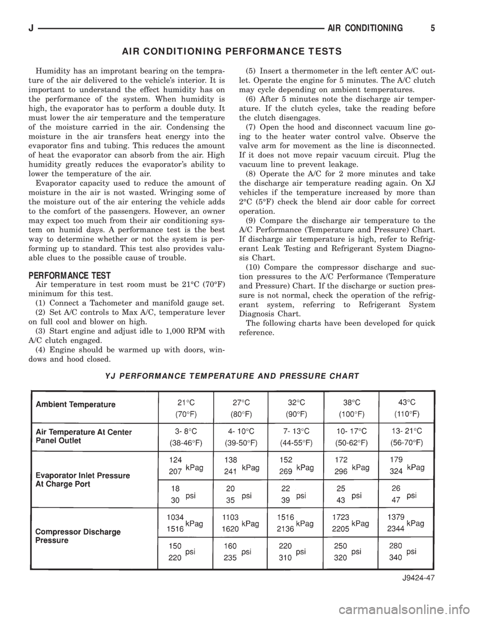
(9) Compare the discharge air temperature to the
A/C Performance (Temperature and Pressure) Chart.
If discharge air temperature is high, refer to Refrig-
erant Leak Testing and Refrigerant System Diagno-
sis Chart.
(10) Compare the compressor discharge and suc-
tion pressures to the A/C Performance (Temperature
and Pressure) Chart. If the discharge or suction pres-
sure is not normal, check the operation of the refrig-
erant system, referring to Refrigerant System
Diagnosis Chart.
The following charts have been developed for quick
reference.
YJ PERFORMANCE TEMPERATURE AND PRESSURE CHART
JAIR CONDITIONING5