1994 JEEP CHEROKEE maint
[x] Cancel search: maintPage 1272 of 1784
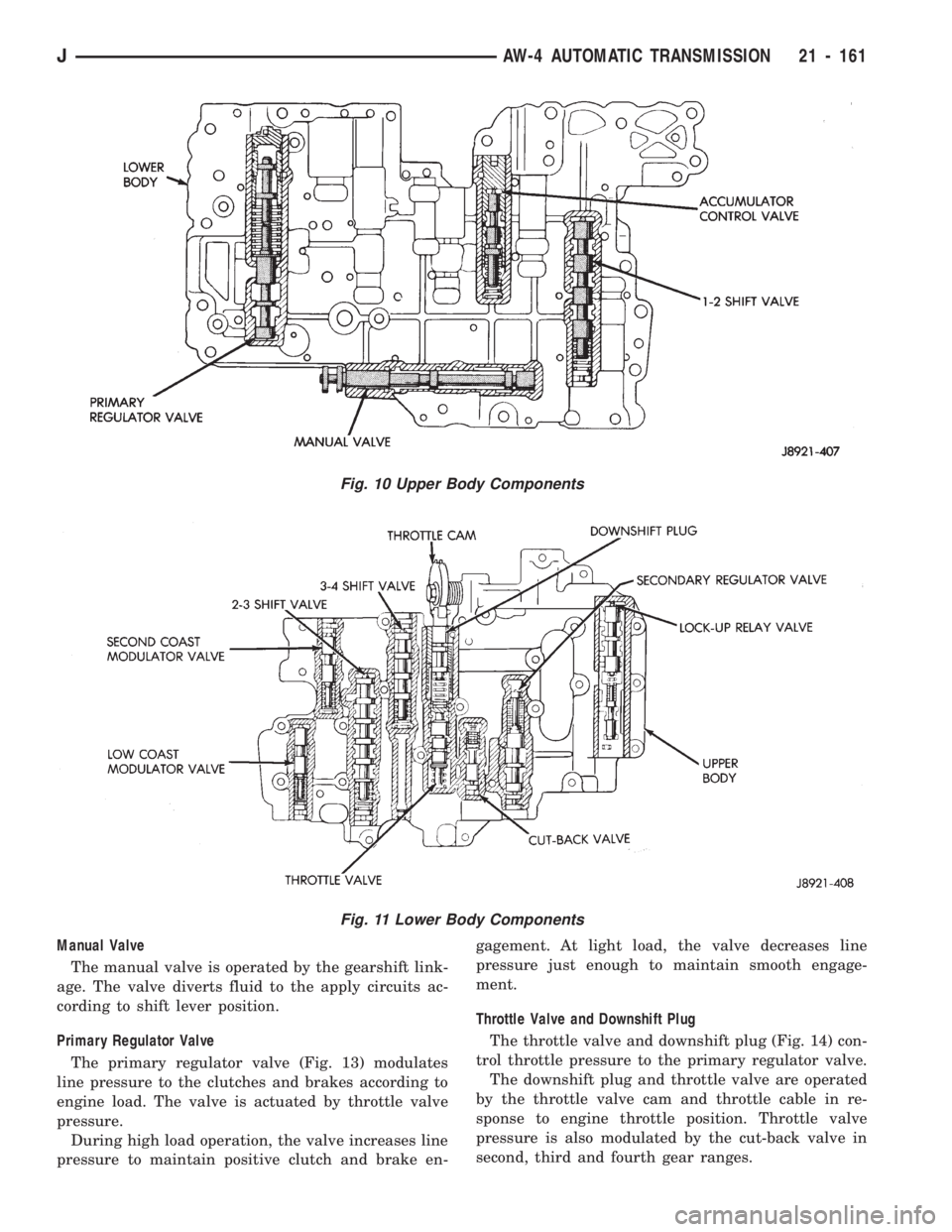
Manual Valve
The manual valve is operated by the gearshift link-
age. The valve diverts fluid to the apply circuits ac-
cording to shift lever position.
Primary Regulator Valve
The primary regulator valve (Fig. 13) modulates
line pressure to the clutches and brakes according to
engine load. The valve is actuated by throttle valve
pressure.
During high load operation, the valve increases line
pressure to maintain positive clutch and brake en-gagement. At light load, the valve decreases line
pressure just enough to maintain smooth engage-
ment.
Throttle Valve and Downshift Plug
The throttle valve and downshift plug (Fig. 14) con-
trol throttle pressure to the primary regulator valve.
The downshift plug and throttle valve are operated
by the throttle valve cam and throttle cable in re-
sponse to engine throttle position. Throttle valve
pressure is also modulated by the cut-back valve in
second, third and fourth gear ranges.
Fig. 11 Lower Body Components
Fig. 10 Upper Body Components
JAW-4 AUTOMATIC TRANSMISSION 21 - 161
Page 1279 of 1784
(2) Verify transmission throttle cable operation.
Repair or replace cable if necessary.
(3) Check engine throttle operation. Operate accel-
erator pedal and observe injector throttle plate move-
ment. Adjust linkage if throttle plate does not reach
wide open position.
(4) Check transmission fluid level when fluid is at
normal operating temperature. Start engine. Shift
transmission through all gear ranges then back to
Neutral. Correct level is to Full or Add mark on dip-
stick with engine at curb idle speed.
(5) Check and adjust park/neutral position switch
if necessary.
(6) Check throttle position sensor adjustment and
operation. Adjust the sensor if necessary.
MANUAL SHIFTING TEST
(1) This test determines if problem is related to
mechanical or electrical component.
(2) Stop engine and disconnect transmission con-
trol module or module fuse.
(3) Road test vehicle. Shift transmission into each
gear range. Transmission should operate as follows:
²lock in Park
²back up in Reverse
²not move in Neutral
²provide first gear only with shift lever in 1-2 posi-
tion
²operate in third gear only with shift lever in 3 po-
sition
²operate in overdrive fourth gear in D position
(4) If transmission operates as described, proceed
to next step. However, if forward gear ranges were
difficult to distinguish (all feel the same), or vehicle
would not back up, refer to diagnosis charts. Do not
perform stall or time lag tests.
CAUTION: Do not overspeed the engine during the
next test step. Ease off the throttle and allow the
vehicle to slow before downshifting.
(5) Continue road test. Manually downshift trans-
mission from D to 3, and from 3 to 1-2 position. Then
manually upshift transmission through forward
ranges again.
(6) If transmission operation is OK, perform stall,
time lag and pressure tests. If transmission shifting
problem is encountered, refer to diagnosis charts.
(7) If a problem still exists, continue testing with
DRB II scan tool.
HYDRAULIC PRESSURE TEST
PRESSURE TEST PROCEDURE
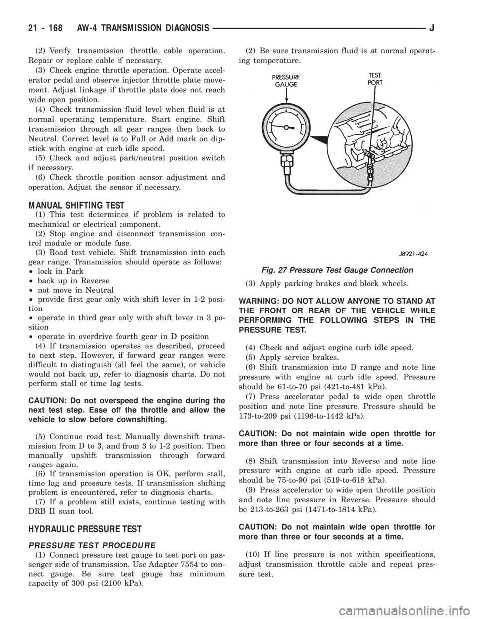
(1) Connect pressure test gauge to test port on pas-
senger side of transmission. Use Adapter 7554 to con-
nect gauge. Be sure test gauge has minimum
capacity of 300 psi (2100 kPa).(2) Be sure transmission fluid is at normal operat-
ing temperature.
(3) Apply parking brakes and block wheels.
WARNING: DO NOT ALLOW ANYONE TO STAND AT
THE FRONT OR REAR OF THE VEHICLE WHILE
PERFORMING THE FOLLOWING STEPS IN THE
PRESSURE TEST.
(4) Check and adjust engine curb idle speed.
(5) Apply service brakes.
(6) Shift transmission into D range and note line
pressure with engine at curb idle speed. Pressure
should be 61-to-70 psi (421-to-481 kPa).
(7) Press accelerator pedal to wide open throttle
position and note line pressure. Pressure should be
173-to-209 psi (1196-to-1442 kPa).
CAUTION: Do not maintain wide open throttle for
more than three or four seconds at a time.
(8) Shift transmission into Reverse and note line
pressure with engine at curb idle speed. Pressure
should be 75-to-90 psi (519-to-618 kPa).
(9) Press accelerator to wide open throttle position
and note line pressure in Reverse. Pressure should
be 213-to-263 psi (1471-to-1814 kPa).
CAUTION: Do not maintain wide open throttle for
more than three or four seconds at a time.
(10) If line pressure is not within specifications,
adjust transmission throttle cable and repeat pres-
sure test.
Fig. 27 Pressure Test Gauge Connection
21 - 168 AW-4 TRANSMISSION DIAGNOSISJ
Page 1280 of 1784
PRESSURE TEST ANALYSIS
If pressures in D and Reverse are higher than
specified, check for the following:
²throttle cable loose, worn, binding or out of adjust-
ment
²throttle valve, downshift plug, throttle cam, or pri-
mary regulator valve are sticking, worn or damaged
If pressures in D and Reverse are lower than spec-
ified, check for following:
²throttle cable loose, worn, binding or out of adjust-
ment
²throttle valve, downshift plug, throttle cam stick-
ing, worn or damaged
²primary regulator valve sticking, worn, or dam-
aged
²oil pump gears or housing worn or damaged
²overdrive clutch worn or damaged
If pressures are low in D range only, check for fol-
lowing:
²forward clutch worn or damaged
²fluid leakage in D range circuit (component seal
and O-rings)
If pressures are low in Reverse only, check for fol-
lowing:
²shift cable and manual valve out of adjustment
²fluid leakage in reverse circuit (component seal
and O-rings)
²direct clutch worn or damaged
²first/reverse brake worn or damaged
TORQUE CONVERTER STALL TEST
Stall testing checks the holding ability of the trans-
mission clutches and brakes and of the torque con-
verter stator overrunning clutch.
(1) Be sure transmission fluid is at normal operat-
ing temperature.
(2) Connect tachometer to engine. Position tachom-
eter so it can be viewed from drivers seat.
(3) Apply parking brakes and block wheels.
(4) Apply and hold service brakes.
(5) Shift transfer case into 2H position. On models
with NP249 transfer case, leave transfer case in 4H
position.
(6) Start engine.
WARNING: DO NOT ALLOW ANYONE TO STAND AT
THE FRONT OR REAR OF THE VEHICLE DURING
THE TEST.
(7) Shift transmission into D range.
(8) Press accelerator pedal to wide open throttle
position and note maximum engine rpm. Stall speed
should be 2100 to 2400 rpm in D range.
CAUTION: Do not maintain wide open throttle for
more than 3-4 seconds at a time.(9) Release throttle and shift transmission into
Neutral. Allow transmission fluid to cool for 15-20
seconds.
(10) Shift transmission into Reverse.
(11) Press accelerator down to wide open throttle
position and note maximum engine rpm. Stall speed
should be 2100-to-2400 rpm in Reverse.
STALL SPEED TEST ANALYSIS
If engine rpm is lower than specified in D and Re-
verse, check for the following:
²engine output/performance insufficient
²stator overrunning clutch in torque converter not
holding if engine speed was 1500 rpm or less.
If stall speed in D range is higher than specified,
check for the following:
²line pressure low
²forward clutch slipping
²No. 2 one-way clutch not holding
²overdrive one-way clutch not holding
If stall speed in Reverse was higher than specified,
check for the following:
²line pressure low
²direct clutch slipping
²first/ reverse brake slipping
²overdrive one-way clutch not holding
If stall speeds were higher than specified in both D
and Reverse, check for the following:
²low fluid level
²line pressure low
²overdrive one-way clutch not holding
TIME LAG TEST
This test checks general condition of the overdrive
clutch, forward clutch, rear clutch and first/reverse
brake. Condition is indicated by the amount of time
required for clutch/brake engagement with the en-
gine at curb idle speed. Engagement time is mea-
sured for D and Reverse positions. A stop watch is
recommended for test accuracy.
TEST PROCEDURE
(1) Check and adjust transmission fluid level if
necessary.
(2) Bring transmission to normal operating tem-
perature.
(3) Apply parking brakes and turn off air condi-
tioning unit.
(4) Shift transfer case into 2H range. On models
with NP249 transfer case, leave transfer case in 4H
range.
(5) Start engine and check curb idle speed. Adjust
speed if necessary. Curb idle must be correct to en-
sure accurate test results.
(6) Shift transmission into Neutral and set stop
watch.
(7) During following test steps, start stop watch as
soon as shift lever reaches D and Reverse ranges.
JAW-4 TRANSMISSION DIAGNOSIS 21 - 169
Page 1446 of 1784
²Noise
²Handling
²Durability
²Tread life
²Traction
²Rolling resistance
²Speed capability
Original equipment tires should be used when re-
placement is needed.
Refer to the placard on the vehicle or the
Owner's Manual for the correct replacement
tire.
Failure to use original or equivalent replacement
tires may adversely affect the handling of the vehi-
cle.
The use of oversize tiresis not recommended.
They may cause interference with vehicle suspension
and steering travel. This can cause tire damage or
failure.
WARNING: FAILURE TO EQUIP THE VEHICLE WITH
TIRES HAVING ADEQUATE LOAD CAPABILITY CAN
RESULT IN SUDDEN TIRE FAILURE.
ROTATION
Tires on the front and rear axles operate at differ-
ent loads and perform different steering, driving, and
braking functions. For these reasons, the tires wear
at unequal rates. They may also develop irregular
wear patterns. These effects can be reduced by rotat-
ing the tires according to the maintenance schedule
in the Owners Manual. This will improve tread life,
traction and maintain a smooth quiet ride.
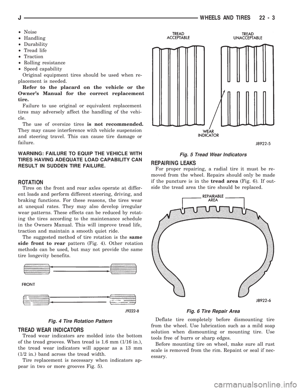
The suggested method of tire rotation is thesame
side front to rearpattern (Fig. 4). Other rotation
methods can be used, but may not provide the same
tire longevity benefits.
TREAD WEAR INDICATORS
Tread wear indicators are molded into the bottom
of the tread grooves. When tread is 1.6 mm (1/16 in.),
the tread wear indicators will appear as a 13 mm
(1/2 in.) band across the tread width.
Tire replacement is necessary when indicators ap-
pear in two or more grooves Fig. 5).
REPAIRING LEAKS
For proper repairing, a radial tire it must be re-
moved from the wheel. Repairs should only be made
if the puncture is in thetread area(Fig. 6). If out-
side the tread area the tire should be replaced.
Deflate tire completely before dismounting tire
from the wheel. Use lubrication such as a mild soap
solution when dismounting or mounting tire. Use
tools free of burrs or sharp edges.
Before mounting tire on wheel, make sure all rust
scale is removed from the rim. Repaint or seal if nec-
essary.
Fig. 4 Tire Rotation Pattern
Fig. 5 Tread Wear Indicators
Fig. 6 Tire Repair Area
JWHEELS AND TIRES 22 - 3
Page 1452 of 1784
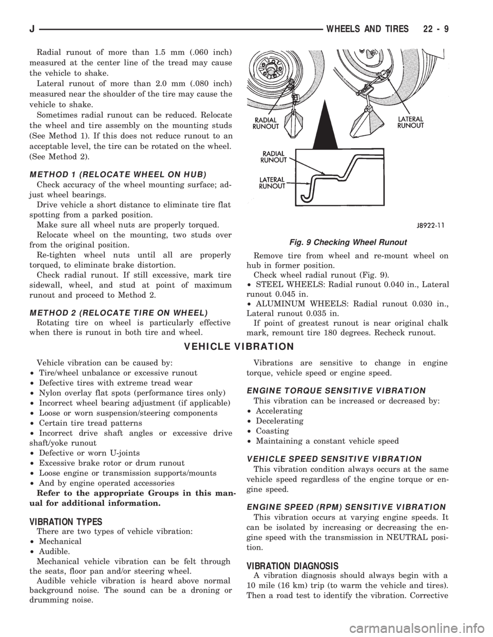
Radial runout of more than 1.5 mm (.060 inch)
measured at the center line of the tread may cause
the vehicle to shake.
Lateral runout of more than 2.0 mm (.080 inch)
measured near the shoulder of the tire may cause the
vehicle to shake.
Sometimes radial runout can be reduced. Relocate
the wheel and tire assembly on the mounting studs
(See Method 1). If this does not reduce runout to an
acceptable level, the tire can be rotated on the wheel.
(See Method 2).
METHOD 1 (RELOCATE WHEEL ON HUB)
Check accuracy of the wheel mounting surface; ad-
just wheel bearings.
Drive vehicle a short distance to eliminate tire flat
spotting from a parked position.
Make sure all wheel nuts are properly torqued.
Relocate wheel on the mounting, two studs over
from the original position.
Re-tighten wheel nuts until all are properly
torqued, to eliminate brake distortion.
Check radial runout. If still excessive, mark tire
sidewall, wheel, and stud at point of maximum
runout and proceed to Method 2.
METHOD 2 (RELOCATE TIRE ON WHEEL)
Rotating tire on wheel is particularly effective
when there is runout in both tire and wheel.Remove tire from wheel and re-mount wheel on
hub in former position.
Check wheel radial runout (Fig. 9).
²STEEL WHEELS: Radial runout 0.040 in., Lateral
runout 0.045 in.
²ALUMINUM WHEELS: Radial runout 0.030 in.,
Lateral runout 0.035 in.
If point of greatest runout is near original chalk
mark, remount tire 180 degrees. Recheck runout.
VEHICLE VIBRATION
Vehicle vibration can be caused by:
²Tire/wheel unbalance or excessive runout
²Defective tires with extreme tread wear
²Nylon overlay flat spots (performance tires only)
²Incorrect wheel bearing adjustment (if applicable)
²Loose or worn suspension/steering components
²Certain tire tread patterns
²Incorrect drive shaft angles or excessive drive
shaft/yoke runout
²Defective or worn U-joints
²Excessive brake rotor or drum runout
²Loose engine or transmission supports/mounts
²And by engine operated accessories
Refer to the appropriate Groups in this man-
ual for additional information.
VIBRATION TYPES
There are two types of vehicle vibration:
²Mechanical
²Audible.
Mechanical vehicle vibration can be felt through
the seats, floor pan and/or steering wheel.
Audible vehicle vibration is heard above normal
background noise. The sound can be a droning or
drumming noise.Vibrations are sensitive to change in engine
torque, vehicle speed or engine speed.
ENGINE TORQUE SENSITIVE VIBRATION
This vibration can be increased or decreased by:
²Accelerating
²Decelerating
²Coasting
²Maintaining a constant vehicle speed
VEHICLE SPEED SENSITIVE VIBRATION
This vibration condition always occurs at the same
vehicle speed regardless of the engine torque or en-
gine speed.
ENGINE SPEED (RPM) SENSITIVE VIBRATION
This vibration occurs at varying engine speeds. It
can be isolated by increasing or decreasing the en-
gine speed with the transmission in NEUTRAL posi-
tion.
VIBRATION DIAGNOSIS
A vibration diagnosis should always begin with a
10 mile (16 km) trip (to warm the vehicle and tires).
Then a road test to identify the vibration. Corrective
Fig. 9 Checking Wheel Runout
JWHEELS AND TIRES 22 - 9
Page 1456 of 1784
BODY COMPONENTSÐXJ VEHICLES
CONTENTS
page page
DOORS............................... 34
EXTERIOR COMPONENTS................. 3
FIXED WINDOW GLASS................. 73GENERAL BODY SERVICE INFORMATION.... 1
INTERIOR COMPONENTS................ 91
UNDERBODY COMPONENTS.............. 84
GENERAL BODY SERVICE INFORMATION
RIGHT HAND DRIVE VEHICLES
The XJ Body Components procedures in this sec-
tion were developed on a left hand drive (LHD) vehi-
cle. Unless a component is unique to a right hand
drive vehicle, it will not be specifically covered in
this section, i.e. cargo barrier. In general, compo-
nents on left hand drive vehicles will be located on
the opposite side in right hand drive vehicles.
LABELS/DECALS/PLATES
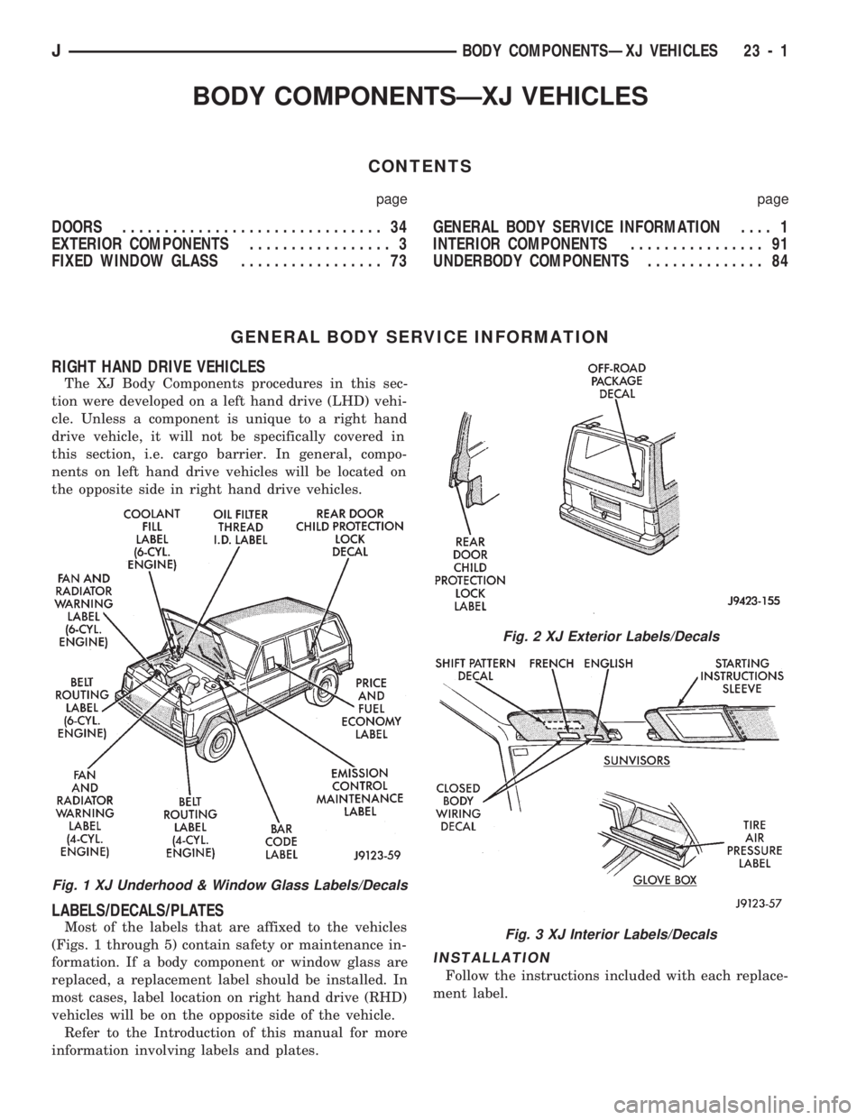
Most of the labels that are affixed to the vehicles
(Figs. 1 through 5) contain safety or maintenance in-
formation. If a body component or window glass are
replaced, a replacement label should be installed. In
most cases, label location on right hand drive (RHD)
vehicles will be on the opposite side of the vehicle.
Refer to the Introduction of this manual for more
information involving labels and plates.
INSTALLATION
Follow the instructions included with each replace-
ment label.
Fig. 1 XJ Underhood & Window Glass Labels/Decals
Fig. 2 XJ Exterior Labels/Decals
Fig. 3 XJ Interior Labels/Decals
JBODY COMPONENTSÐXJ VEHICLES 23 - 1
Page 1635 of 1784
REPLACEMENT
(1) Mark the outline of the existing hinge on the
body and the door with a wax pencil for installation
alignment reference.
When removing the door or hinge DO NOT
discard the plastic shims or the hinge pin.
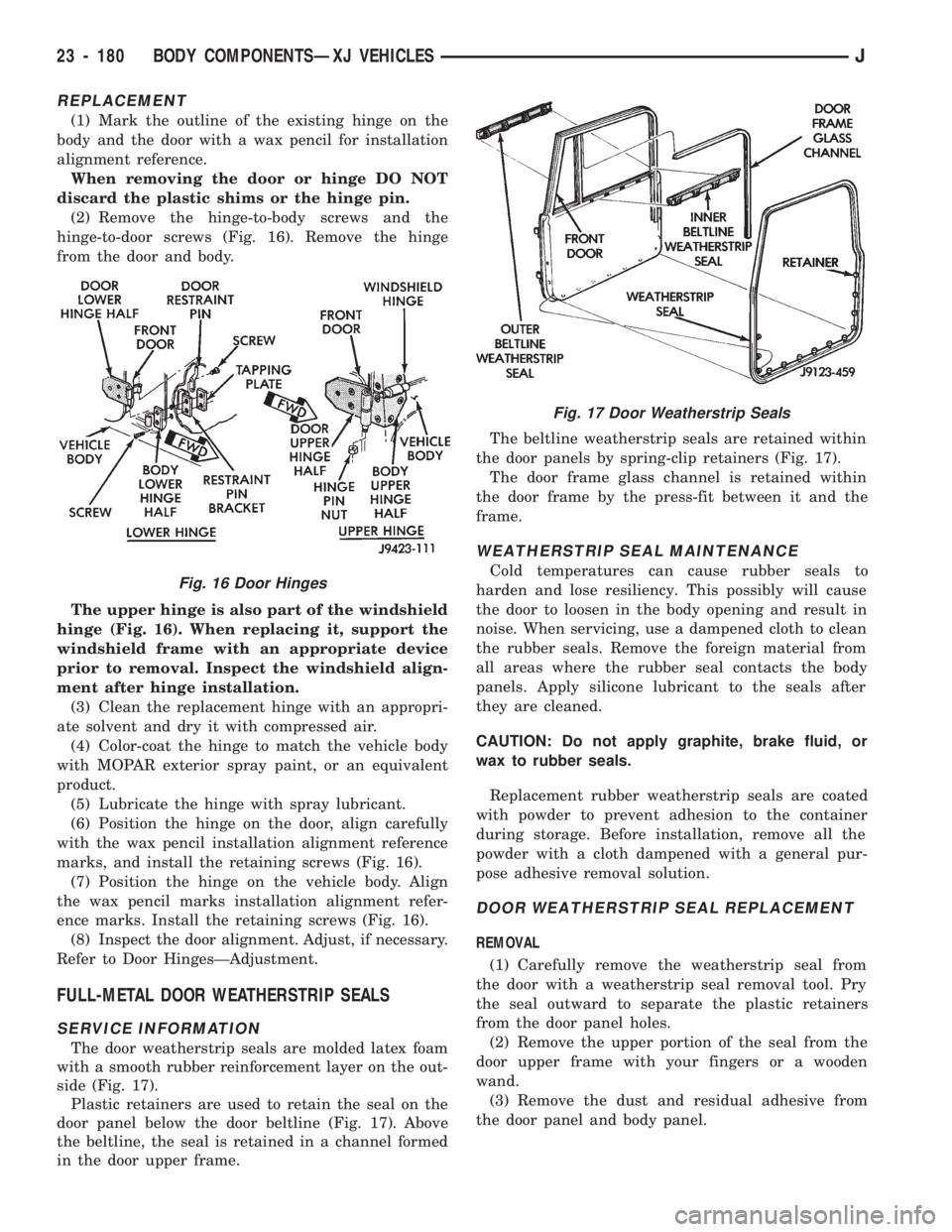
(2) Remove the hinge-to-body screws and the
hinge-to-door screws (Fig. 16). Remove the hinge
from the door and body.
The upper hinge is also part of the windshield
hinge (Fig. 16). When replacing it, support the
windshield frame with an appropriate device
prior to removal. Inspect the windshield align-
ment after hinge installation.
(3) Clean the replacement hinge with an appropri-
ate solvent and dry it with compressed air.
(4) Color-coat the hinge to match the vehicle body
with MOPAR exterior spray paint, or an equivalent
product.
(5) Lubricate the hinge with spray lubricant.
(6) Position the hinge on the door, align carefully
with the wax pencil installation alignment reference
marks, and install the retaining screws (Fig. 16).
(7) Position the hinge on the vehicle body. Align
the wax pencil marks installation alignment refer-
ence marks. Install the retaining screws (Fig. 16).
(8) Inspect the door alignment. Adjust, if necessary.
Refer to Door HingesÐAdjustment.
FULL-METAL DOOR WEATHERSTRIP SEALS
SERVICE INFORMATION
The door weatherstrip seals are molded latex foam
with a smooth rubber reinforcement layer on the out-
side (Fig. 17).
Plastic retainers are used to retain the seal on the
door panel below the door beltline (Fig. 17). Above
the beltline, the seal is retained in a channel formed
in the door upper frame.The beltline weatherstrip seals are retained within
the door panels by spring-clip retainers (Fig. 17).
The door frame glass channel is retained within
the door frame by the press-fit between it and the
frame.
WEATHERSTRIP SEAL MAINTENANCE
Cold temperatures can cause rubber seals to
harden and lose resiliency. This possibly will cause
the door to loosen in the body opening and result in
noise. When servicing, use a dampened cloth to clean
the rubber seals. Remove the foreign material from
all areas where the rubber seal contacts the body
panels. Apply silicone lubricant to the seals after
they are cleaned.
CAUTION: Do not apply graphite, brake fluid, or
wax to rubber seals.
Replacement rubber weatherstrip seals are coated
with powder to prevent adhesion to the container
during storage. Before installation, remove all the
powder with a cloth dampened with a general pur-
pose adhesive removal solution.
DOOR WEATHERSTRIP SEAL REPLACEMENT
REMOVAL
(1) Carefully remove the weatherstrip seal from
the door with a weatherstrip seal removal tool. Pry
the seal outward to separate the plastic retainers
from the door panel holes.
(2) Remove the upper portion of the seal from the
door upper frame with your fingers or a wooden
wand.
(3) Remove the dust and residual adhesive from
the door panel and body panel.
Fig. 17 Door Weatherstrip Seals
Fig. 16 Door Hinges
23 - 180 BODY COMPONENTSÐXJ VEHICLESJ
Page 1664 of 1784
HEATING AND AIR CONDITIONING
CONTENTS
page page
CLIMATE CONTROL SYSTEMÐXJ VEHICLES . 22
CLIMATE CONTROL SYSTEMÐYJ VEHICLES . 37
COMPRESSOR OVERHAUL............... 17
GENERAL INFORMATION.................. 1SERVICE DIAGNOSISÐELECTRICAL........ 14
SERVICE DIAGNOSISÐMECHANICAL........ 8
TORQUE SPECIFICATIONS................ 45
GENERAL INFORMATION
INDEX
page page
A/C Operation............................ 1
Compressor Oil Level...................... 6
Pressure Gauge and Manifold Assembly........ 2
Refrigerant (R-12)......................... 1
Service Precautions........................ 2Service Valves........................... 3
System Charge........................... 5
System Discharge......................... 4
System Evacuation........................ 4
A/C OPERATION
The compressor increases the pressure and temper-
ature of the refrigerant. The heated refrigerant vapor
is then pumped into the condenser where it cools by
the air passing over the condenser fins. As the refrig-
erant cools in the condenser, it condenses into a liq-
uid. Still under high pressure, the liquid refrigerant
passes into the receiver. The receiver acts as a reser-
voir to furnish refrigerant to the expansion (H) valve
at all times. From the receiver, the high pressure liq-
uid refrigerant passes to the expansion (H) valve.
The expansion (H) valve meters refrigerant into the
evaporator where a low pressure is maintained by
the suction side of the compressor. As it enters the
evaporator, the refrigerant immediately begins to
boil by absorbing heat from the air passing over the
evaporator core. Having given up its heat to boil the
refrigerant, the air is cooled and passes into the pas-
senger compartment of the vehicle. From the evapo-
rator the vaporized refrigerant is drawn back to the
compressor to repeat the cycle.
REFRIGERANT (R-12)
It is illegal to release R-12 into the atmosphere.
SAFETY PRECAUTIONS
WARNING: EXTREME CARE MUST BE TAKEN TO
PREVENT ANY LIQUID REFRIGERANT FROM COM-
ING IN CONTACT WITH THE SKIN AND ESPE-
CIALLY THE EYES. ALWAYS WEAR SAFETYGOGGLES WHEN SERVICING ANY PART OF THE
REFRIGERANT SYSTEM. IF EYE CONTACT IS
MADE, APPLY A FEW DROPS OF MINERAL OIL TO
THE EYES AND FLUSH WITH WATER FOR SEV-
ERAL MINUTES. SEEK MEDICAL ATTENTION IMME-
DIATELY.
The refrigerant used in the air conditioner system
is Refrigerant-12 (R-12). R-12 is nonexplosive, non-
flammable, non-corrosive, has practically no odor and
is heavier than air. Although it is classified as a safe
refrigerant, certain precautions must be observed to
protect the parts involved and the person who is
working on the unit. Liquid R-12, at normal atmo-
sphere pressures and temperatures, evaporates so
quickly that it has the tendency to freeze anything it
contacts.
WARNING: TO AVOID A DANGEROUS EXPLOSION,
NEVER WELD OR STEAM CLEAN NEAR AIR CON-
DITIONING LINES OR COMPONENTS. DO NOT
HEAT R-12 ABOVE 52ÉC (125ÉF).
The R-12 in the system is always under pressure.
Because the system is tightly sealed, heat applied to
any part could cause this pressure to build up exces-
sively.
JHEATING AND AIR CONDITIONING 24 - 1