1994 JEEP CHEROKEE clutch
[x] Cancel search: clutchPage 1183 of 1784
(5) Line pressure should be 54-60 psi (372-414
kPa) with throttle lever forward and gradually in-
crease to 90-96 psi (620-662 kPa) as lever is moved
rearward.
Test Three-Transmission In D Range
This test checks pressure regulation and con-
dition of the front and rear clutch circuits.
Both test gauges are required for this test.
(1) Connect one test gauge to line pressure port
and other gauge to front servo pressure port (Fig. 4).
Either gauge can be used at either port.
(2) Start and run engine at 1600 rpm.
(3) Move selector lever two detents rearward from
full forward position. This is D range.
(4) Read pressures on both gauges as transmission
throttle lever is moved from full forward to full rear-
ward position.
(5) Line pressure should be 54-60 psi (372-414
kPa) with throttle lever forward and gradually in-
crease as lever is moved rearward.
(6) Front servo is pressurized only in D range and
should be same as line pressure within 3 psi (21
kPa), up to downshift point.
Test Four-Transmission In Reverse
This test checks pump output, pressure regu-
lation and the front clutch and rear servo cir-
cuits. Use 300 psi Pressure Test Gauge C-3293
for this test.
(1) Connect pressure test gauge to rear servo port
(Fig. 5).
(2) Start and run engine at 1600 rpm for test.
(3) Move valve body selector lever four detents
rearward from full forward position. This is Reverse
range.
(4) Move throttle lever all way forward then all the
way rearward and note gauge readings.
(5) Pressure should be 145 - 175 psi (1000-1207
kPa) with lever forward and increase to 230 - 280 psi
(1586-1931 kPa) as lever is moved rearward.
Test Five-Governor Pressure
This test checks governor operation by mea-
suring governor pressure response to changes
in engine speed. It is usually not necessary to
check governor operation unless shift speeds
are incorrect or if the transmission will not
shift up or down. Use 100 psi Pressure Test
Gauge C-3292 for this test.
(1) Connect test gauge to governor pressure port
(Figs. 5 and 6).
(2) Move selector lever to D range.
(3) Apply service brakes. Start and run engine at
curb idle speed and note pressure. At idle and with
wheels stopped, pressure should be zero to 1-1/2 psi
maximum. If pressure exceeds this figure, governor
valve or weights are sticking open.(4) Slowly increase engine speed and observe
speedometer and pressure test gauge. Governor pres-
sure should increase in proportion to vehicle speed
(approximately 1 psi for every 1 mph shown on
speedometer).
(5) Governor pressure rise should be smooth and
drop back to 0 to 1-1/2 psi when throttle is closed
and wheels are stopped.
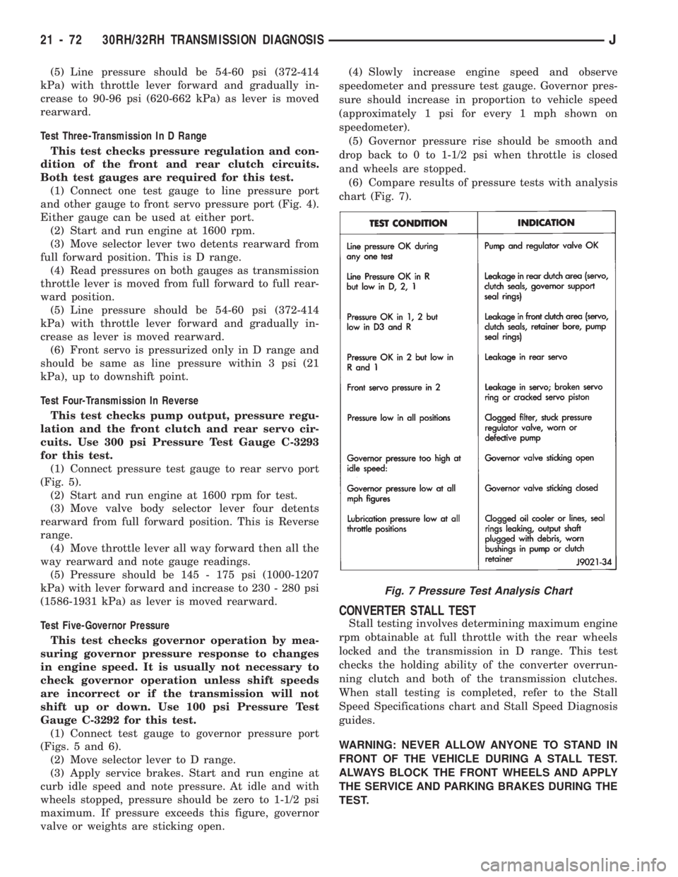
(6) Compare results of pressure tests with analysis
chart (Fig. 7).
CONVERTER STALL TEST
Stall testing involves determining maximum engine
rpm obtainable at full throttle with the rear wheels
locked and the transmission in D range. This test
checks the holding ability of the converter overrun-
ning clutch and both of the transmission clutches.
When stall testing is completed, refer to the Stall
Speed Specifications chart and Stall Speed Diagnosis
guides.
WARNING: NEVER ALLOW ANYONE TO STAND IN
FRONT OF THE VEHICLE DURING A STALL TEST.
ALWAYS BLOCK THE FRONT WHEELS AND APPLY
THE SERVICE AND PARKING BRAKES DURING THE
TEST.
Fig. 7 Pressure Test Analysis Chart
21 - 72 30RH/32RH TRANSMISSION DIAGNOSISJ
Page 1184 of 1784
STALL TEST PROCEDURE
(1) Connect tachometer to engine.
(2) Check and adjust transmission fluid level.
(3) Start and run engine until transmission fluid
reaches normal operating temperature.
(4) Block front wheels.
(5) Fully apply service and parking brakes.
(6) Open throttle completely for no more than five
seconds and record maximum engine rpm registered
on tachometer.
CAUTION: Stall testing causes a rapid increase in
transmission fluid temperature. Do not hold the
throttle open any longer than five seconds. If more
than one stall test is required, run the engine at
1000 rpm with the transmission in Neutral for at
least 20 seconds to cool the fluid.
(7) If engine speed exceeds maximum shown in
stall speed chart, release accelerator immediately.
This indicates that transmission clutch slippage is
occurring.
(8) Shift transmission into Neutral. Run engine for
20 seconds to cool fluid. Then stop engine, shift
transmission into Park and release brakes.
(9) Stall speeds should be in 1700-2000 rpm range.
(10) Refer to Stall Test Diagnosis.
STALL TEST DIAGNOSIS
Stall Speed Too High
If the stall speed exceeds specifications by more
than 200 rpm, transmission clutch slippage is indi-
cated.
Stall Speed Too Low
Low stall speeds with a properly tuned engine in-
dicate a torque converter overrunning clutch prob-
lem. The condition should be confirmed by road
testing prior to converter replacement.
The converter overrunning clutch is slipping when
stall speeds are 250 to 350 rpm below specified min-
imum. And when the vehicle operates properly at
highway speeds but has poor low speed acceleration.
Stall Speed Normal
If stall speeds are normal but abnormal throttle
opening is required to maintain highway speeds, the
converter overrunning clutch is seized and the torque
converter must be replaced.
Converter Noise During Test
A whining noise caused by fluid flow is normal
during a stall test. However, loud metallic noises in-
dicate a damaged converter. To confirm that noise is
originating from the converter, operate the vehicle at
light throttle in Drive and Neutral on a hoist and lis-
ten for noise coming from the converter housing.
AIR PRESSURE TEST
Air pressure testing can be used to check clutch
and band operation with the transmission either in
the vehicle, or on the work bench as a final check af-
ter overhaul.
Air pressure testing requires that the oil pan and
valve body be removed from the transmission.
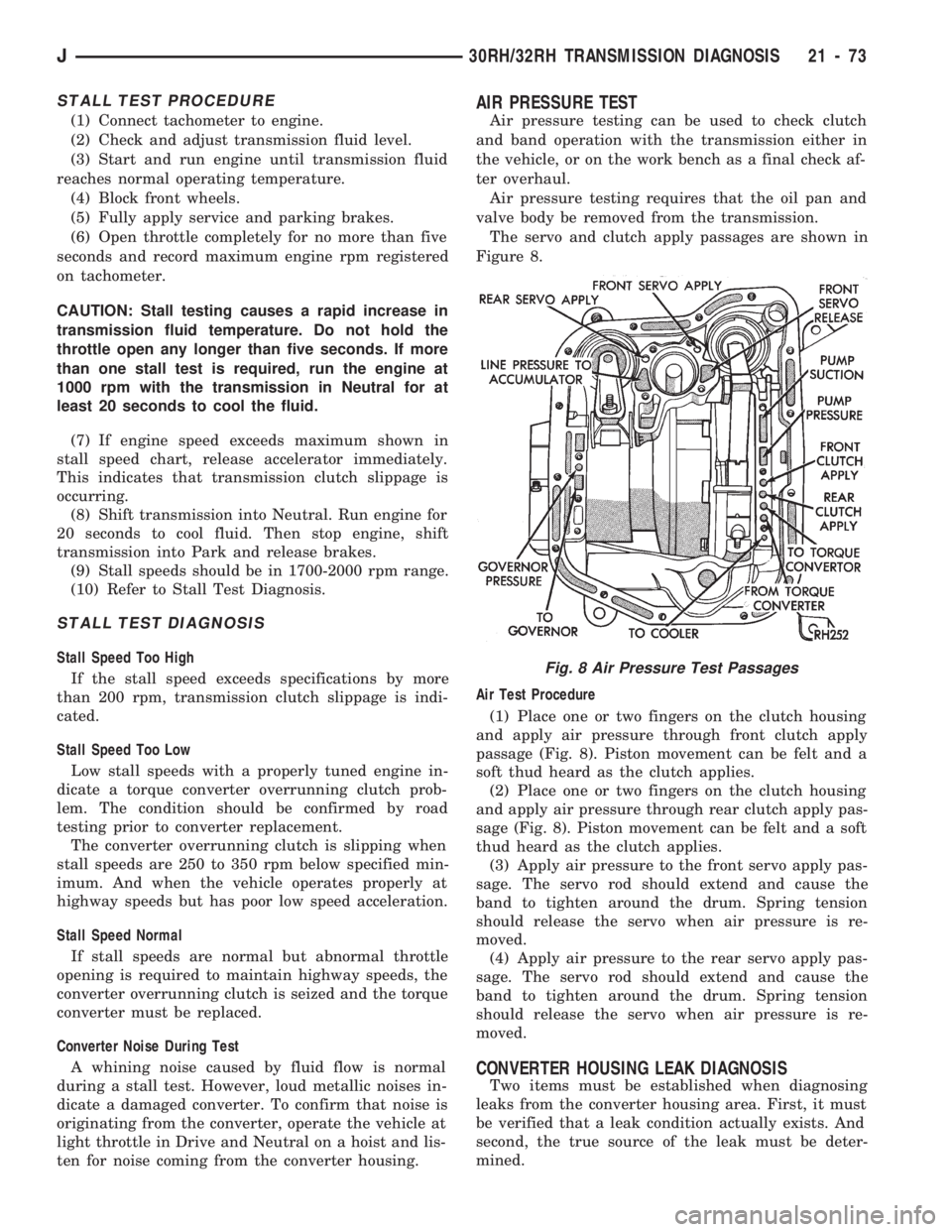
The servo and clutch apply passages are shown in
Figure 8.
Air Test Procedure
(1) Place one or two fingers on the clutch housing
and apply air pressure through front clutch apply
passage (Fig. 8). Piston movement can be felt and a
soft thud heard as the clutch applies.
(2) Place one or two fingers on the clutch housing
and apply air pressure through rear clutch apply pas-
sage (Fig. 8). Piston movement can be felt and a soft
thud heard as the clutch applies.
(3) Apply air pressure to the front servo apply pas-
sage. The servo rod should extend and cause the
band to tighten around the drum. Spring tension
should release the servo when air pressure is re-
moved.
(4) Apply air pressure to the rear servo apply pas-
sage. The servo rod should extend and cause the
band to tighten around the drum. Spring tension
should release the servo when air pressure is re-
moved.
CONVERTER HOUSING LEAK DIAGNOSIS
Two items must be established when diagnosing
leaks from the converter housing area. First, it must
be verified that a leak condition actually exists. And
second, the true source of the leak must be deter-
mined.
Fig. 8 Air Pressure Test Passages
J30RH/32RH TRANSMISSION DIAGNOSIS 21 - 73
Page 1187 of 1784
CONVERTER HOUSING AREA LEAK
CORRECTION
(1) Remove converter.
(2) Tighten front band adjusting screw until band
is tight around clutch retainer. This prevents
clutches from coming out when oil pump is removed.
(3) Remove oil pump and seal. Inspect pump hous-
ing drainback and vent holes for obstructions. Clear
holes with solvent and wire.(4) Inspect pump bushing and converter hub. If
bushing is scored, replace it. If converter hub is
scored, either polish it with crocus cloth or replace
converter if scoring is severe.
(5) Install new pump seal, O-ring, gasket, bushing.
Replace oil pump if cracked, porous or damaged in
any way.
(6) Loosen kickdown lever pin plug two turns. Ap-
ply Permatex No. 2 or equivalent to plug threads and
tighten plug to 17 Nzm (150 in-lbs) torque.
(7) Adjust front band.
(8) Lubricate pump seal and converter hub with
transmission fluid or petroleum jelly and install con-
verter.
(9) Install transmission.
(10) Install converter housing dust shield and
lower vehicle.DIAGNOSIS GUIDES AND CHARTS
The diagnosis charts provide additional reference
for transmission diagnosis.
The hydraulic flow charts outline fluid flow and hy-
draulic circuitry. Circuit operation is provided for all
gear ranges. Normal working pressures are also sup-
plied for each of the various gear ranges.
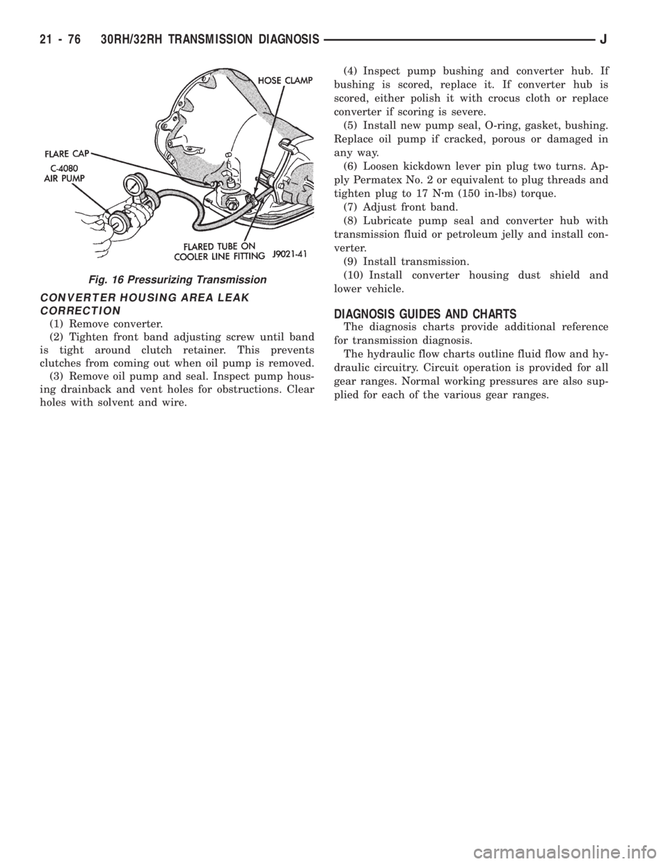
Fig. 16 Pressurizing Transmission
21 - 76 30RH/32RH TRANSMISSION DIAGNOSISJ
Page 1201 of 1784
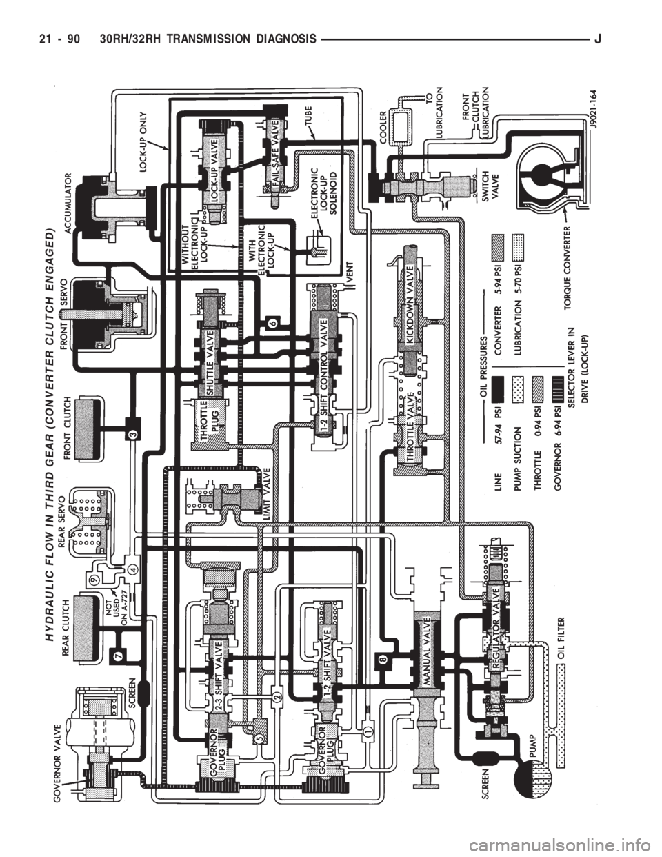
HYDRAULIC FLOW IN THIRD GEAR (CONVERTER CLUTCH ENGAGED)
21 - 90 30RH/32RH TRANSMISSION DIAGNOSISJ
Page 1211 of 1784
OIL FILTER REPLACEMENT
(1) Raise vehicle.
(2) Remove oil pan and drain fluid.
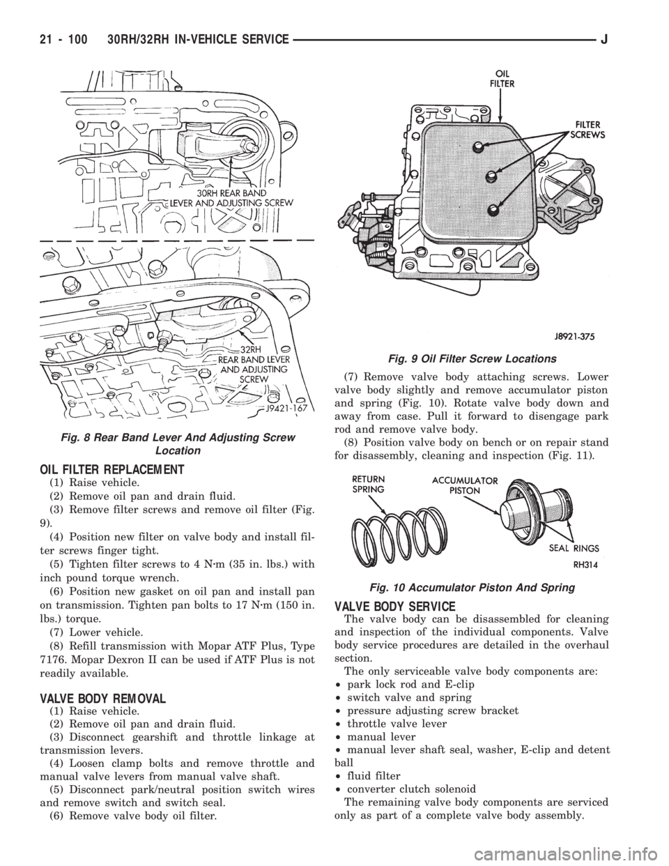
(3) Remove filter screws and remove oil filter (Fig.
9).
(4) Position new filter on valve body and install fil-
ter screws finger tight.
(5) Tighten filter screws to 4 Nzm (35 in. lbs.) with
inch pound torque wrench.
(6) Position new gasket on oil pan and install pan
on transmission. Tighten pan bolts to 17 Nzm (150 in.
lbs.) torque.
(7) Lower vehicle.
(8) Refill transmission with Mopar ATF Plus, Type
7176. Mopar Dexron II can be used if ATF Plus is not
readily available.
VALVE BODY REMOVAL
(1) Raise vehicle.
(2) Remove oil pan and drain fluid.
(3) Disconnect gearshift and throttle linkage at
transmission levers.
(4) Loosen clamp bolts and remove throttle and
manual valve levers from manual valve shaft.
(5) Disconnect park/neutral position switch wires
and remove switch and switch seal.
(6) Remove valve body oil filter.(7) Remove valve body attaching screws. Lower
valve body slightly and remove accumulator piston
and spring (Fig. 10). Rotate valve body down and
away from case. Pull it forward to disengage park
rod and remove valve body.
(8) Position valve body on bench or on repair stand
for disassembly, cleaning and inspection (Fig. 11).
VALVE BODY SERVICE
The valve body can be disassembled for cleaning
and inspection of the individual components. Valve
body service procedures are detailed in the overhaul
section.
The only serviceable valve body components are:
²park lock rod and E-clip
²switch valve and spring
²pressure adjusting screw bracket
²throttle valve lever
²manual lever
²manual lever shaft seal, washer, E-clip and detent
ball
²fluid filter
²converter clutch solenoid
The remaining valve body components are serviced
only as part of a complete valve body assembly.
Fig. 9 Oil Filter Screw Locations
Fig. 10 Accumulator Piston And Spring
Fig. 8 Rear Band Lever And Adjusting Screw
Location
21 - 100 30RH/32RH IN-VEHICLE SERVICEJ
Page 1220 of 1784
CONVERTERÐPUMP SEALÐDRIVE PLATE SERVICE
Drive Plate
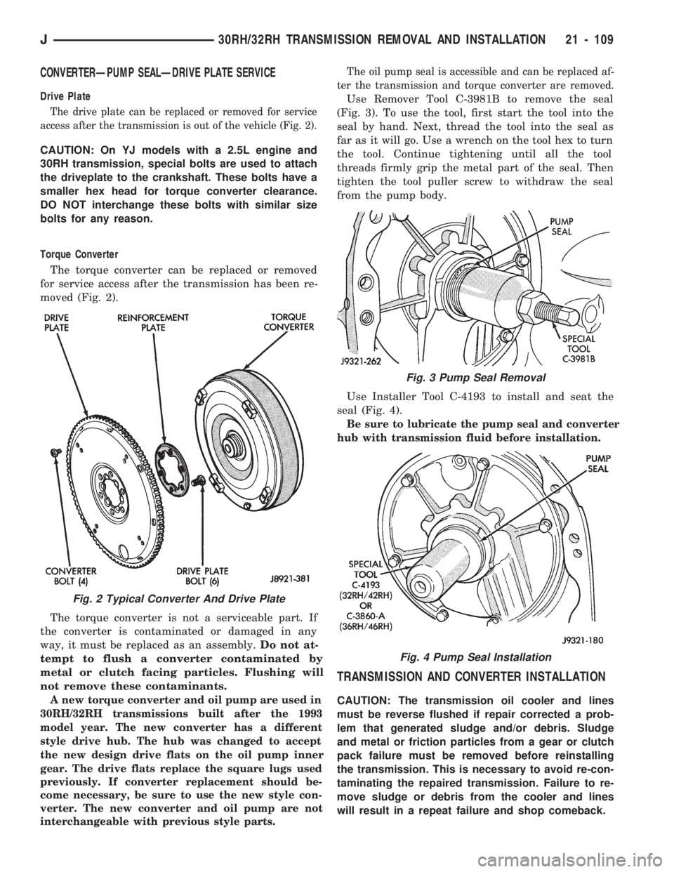
The drive plate can be replaced or removed for service
access after the transmission is out of the vehicle (Fig. 2).
CAUTION: On YJ models with a 2.5L engine and
30RH transmission, special bolts are used to attach
the driveplate to the crankshaft. These bolts have a
smaller hex head for torque converter clearance.
DO NOT interchange these bolts with similar size
bolts for any reason.
Torque Converter
The torque converter can be replaced or removed
for service access after the transmission has been re-
moved (Fig. 2).
The torque converter is not a serviceable part. If
the converter is contaminated or damaged in any
way, it must be replaced as an assembly.Do not at-
tempt to flush a converter contaminated by
metal or clutch facing particles. Flushing will
not remove these contaminants.
A new torque converter and oil pump are used in
30RH/32RH transmissions built after the 1993
model year. The new converter has a different
style drive hub. The hub was changed to accept
the new design drive flats on the oil pump inner
gear. The drive flats replace the square lugs used
previously. If converter replacement should be-
come necessary, be sure to use the new style con-
verter. The new converter and oil pump are not
interchangeable with previous style parts.The oil pump seal is accessible and can be replaced af-
ter the transmission and torque converter are removed.
Use Remover Tool C-3981B to remove the seal
(Fig. 3). To use the tool, first start the tool into the
seal by hand. Next, thread the tool into the seal as
far as it will go. Use a wrench on the tool hex to turn
the tool. Continue tightening until all the tool
threads firmly grip the metal part of the seal. Then
tighten the tool puller screw to withdraw the seal
from the pump body.
Use Installer Tool C-4193 to install and seat the
seal (Fig. 4).
Be sure to lubricate the pump seal and converter
hub with transmission fluid before installation.
TRANSMISSION AND CONVERTER INSTALLATION
CAUTION: The transmission oil cooler and lines
must be reverse flushed if repair corrected a prob-
lem that generated sludge and/or debris. Sludge
and metal or friction particles from a gear or clutch
pack failure must be removed before reinstalling
the transmission. This is necessary to avoid re-con-
taminating the repaired transmission. Failure to re-
move sludge or debris from the cooler and lines
will result in a repeat failure and shop comeback.
Fig. 2 Typical Converter And Drive Plate
Fig. 3 Pump Seal Removal
Fig. 4 Pump Seal Installation
J30RH/32RH TRANSMISSION REMOVAL AND INSTALLATION 21 - 109
Page 1223 of 1784
30RH/32RH TRANSMISSION OVERHAUL
INDEX
page page
Adapter Housing and Park Lock Component
Overhaul............................ 120
Front Clutch Overhaul.................... 125
Front Servo and Band Overhaul............ 136
Governor and Park Gear Overhaul.......... 121
Oil Pump Overhaul...................... 122
Overhaul Service Information............... 118
Overrunning ClutchÐLow-Reverse DrumÐRear
Support Overhaul...................... 118
Planetary Gear Train Overhaul............. 131Rear Clutch Overhaul.................... 128
Rear Servo and Band Overhaul............. 136
Transmission Assembly and Adjustment
Procedures........................... 146
Transmission Assembly Tips............... 146
Transmission Case Cleaning and Inspection . . . 118
Transmission Disassembly................. 112
Valve Body Assembly and Adjustment........ 144
Valve Body Disassembly and Inspection...... 138
TRANSMISSION DISASSEMBLY
(1) Clean transmission exterior with steam gun or
with solvent. Wear eye protection during cleaning
process.
(2) Remove throttle and shift levers from valve
body manual shaft and throttle lever shaft.
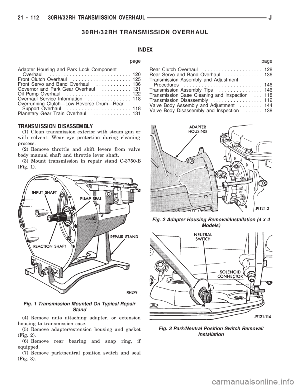
(3) Mount transmission in repair stand C-3750-B
(Fig. 1).
(4) Remove nuts attaching adapter, or extension
housing to transmission case.
(5) Remove adapter/extension housing and gasket
(Fig. 2).
(6) Remove rear bearing and snap ring, if
equipped.
(7) Remove park/neutral position switch and seal
(Fig. 3).
Fig. 1 Transmission Mounted On Typical Repair
Stand
Fig. 2 Adapter Housing Removal/Installation (4 x 4
Models)
Fig. 3 Park/Neutral Position Switch Removal/
Installation
21 - 112 30RH/32RH TRANSMISSION OVERHAULJ
Page 1224 of 1784
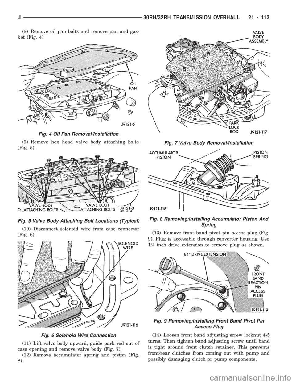
(8) Remove oil pan bolts and remove pan and gas-
ket (Fig. 4).
(9) Remove hex head valve body attaching bolts
(Fig. 5).
(10) Disconnect solenoid wire from case connector
(Fig. 6).
(11) Lift valve body upward, guide park rod out of
case opening and remove valve body (Fig. 7).
(12) Remove accumulator spring and piston (Fig.
8).(13) Remove front band pivot pin access plug (Fig.
9). Plug is accessible through converter housing. Use
1/4 inch drive extension to remove plug as shown.
(14) Loosen front band adjusting screw locknut 4-5
turns. Then tighten band adjusting screw until band
is tight around front clutch retainer. This prevents
front/rear clutches from coming out with pump and
possibly damaging clutch or pump components.
Fig. 4 Oil Pan Removal/Installation
Fig. 5 Valve Body Attaching Bolt Locations (Typical)
Fig. 6 Solenoid Wire Connection
Fig. 7 Valve Body Removal/Installation
Fig. 8 Removing/Installing Accumulator Piston And
Spring
Fig. 9 Removing/Installing Front Band Pivot Pin
Access Plug
J30RH/32RH TRANSMISSION OVERHAUL 21 - 113