Page 1065 of 1784
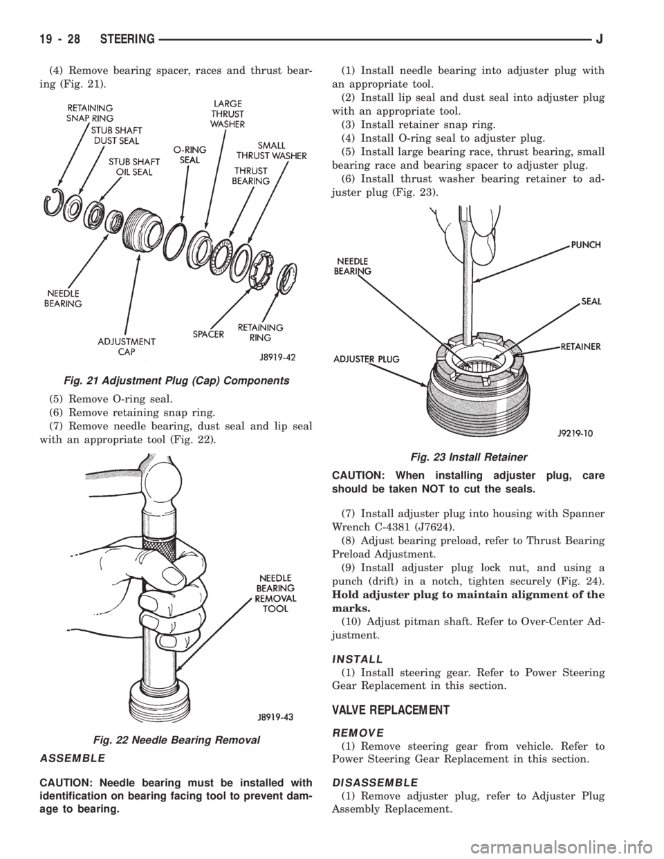
(4) Remove bearing spacer, races and thrust bear-
ing (Fig. 21).
(5) Remove O-ring seal.
(6) Remove retaining snap ring.
(7) Remove needle bearing, dust seal and lip seal
with an appropriate tool (Fig. 22).
ASSEMBLE
CAUTION: Needle bearing must be installed with
identification on bearing facing tool to prevent dam-
age to bearing.(1) Install needle bearing into adjuster plug with
an appropriate tool.
(2) Install lip seal and dust seal into adjuster plug
with an appropriate tool.
(3) Install retainer snap ring.
(4) Install O-ring seal to adjuster plug.
(5) Install large bearing race, thrust bearing, small
bearing race and bearing spacer to adjuster plug.
(6) Install thrust washer bearing retainer to ad-
juster plug (Fig. 23).
CAUTION: When installing adjuster plug, care
should be taken NOT to cut the seals.
(7) Install adjuster plug into housing with Spanner
Wrench C-4381 (J7624).
(8) Adjust bearing preload, refer to Thrust Bearing
Preload Adjustment.
(9) Install adjuster plug lock nut, and using a
punch (drift) in a notch, tighten securely (Fig. 24).
Hold adjuster plug to maintain alignment of the
marks.
(10) Adjust pitman shaft. Refer to Over-Center Ad-
justment.
INSTALL
(1) Install steering gear. Refer to Power Steering
Gear Replacement in this section.
VALVE REPLACEMENT
REMOVE
(1) Remove steering gear from vehicle. Refer to
Power Steering Gear Replacement in this section.
DISASSEMBLE
(1) Remove adjuster plug, refer to Adjuster Plug
Assembly Replacement.
Fig. 21 Adjustment Plug (Cap) Components
Fig. 22 Needle Bearing Removal
Fig. 23 Install Retainer
19 - 28 STEERINGJ
Page 1066 of 1784
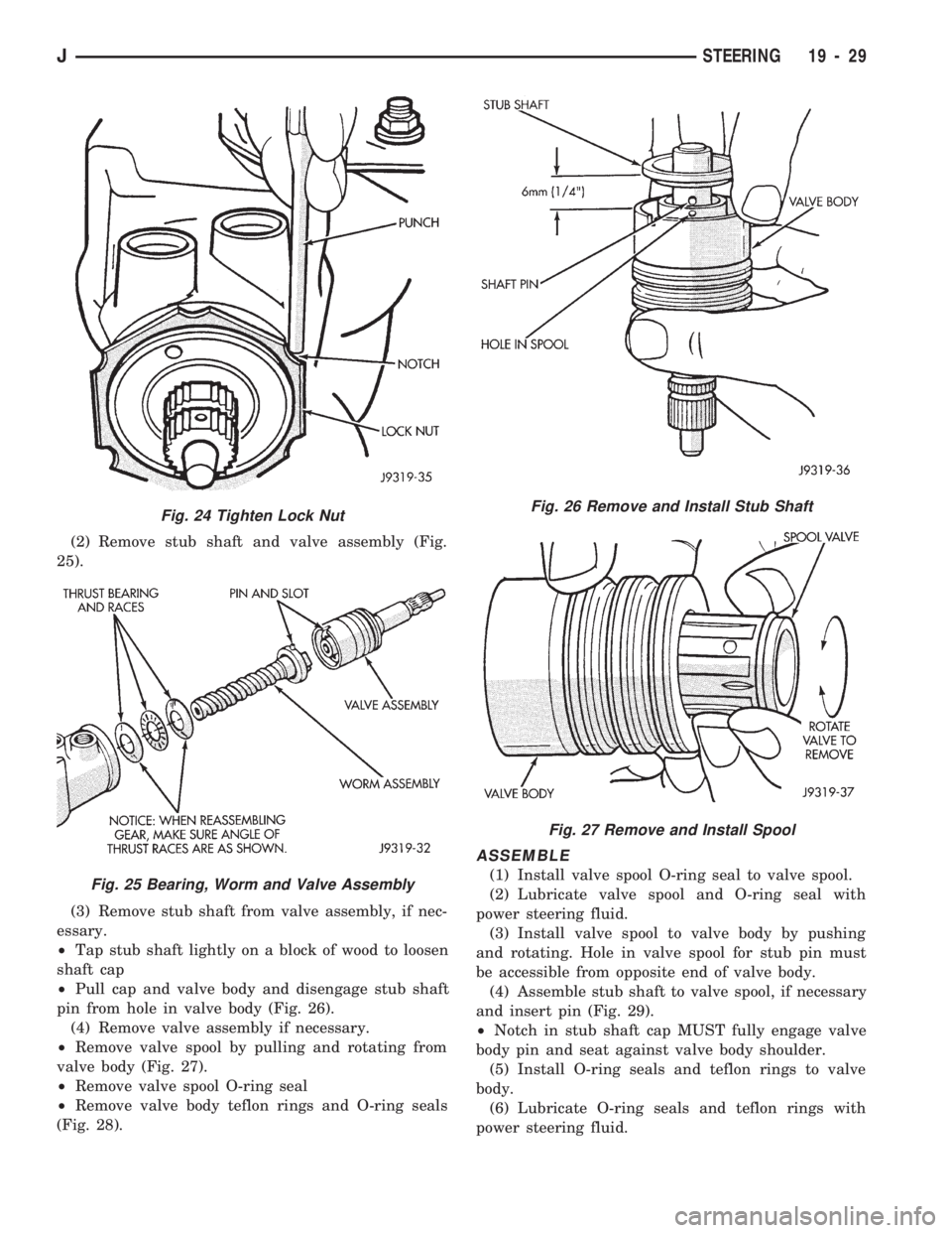
(2) Remove stub shaft and valve assembly (Fig.
25).
(3) Remove stub shaft from valve assembly, if nec-
essary.
²Tap stub shaft lightly on a block of wood to loosen
shaft cap
²Pull cap and valve body and disengage stub shaft
pin from hole in valve body (Fig. 26).
(4) Remove valve assembly if necessary.
²Remove valve spool by pulling and rotating from
valve body (Fig. 27).
²Remove valve spool O-ring seal
²Remove valve body teflon rings and O-ring seals
(Fig. 28).
ASSEMBLE
(1) Install valve spool O-ring seal to valve spool.
(2) Lubricate valve spool and O-ring seal with
power steering fluid.
(3) Install valve spool to valve body by pushing
and rotating. Hole in valve spool for stub pin must
be accessible from opposite end of valve body.
(4) Assemble stub shaft to valve spool, if necessary
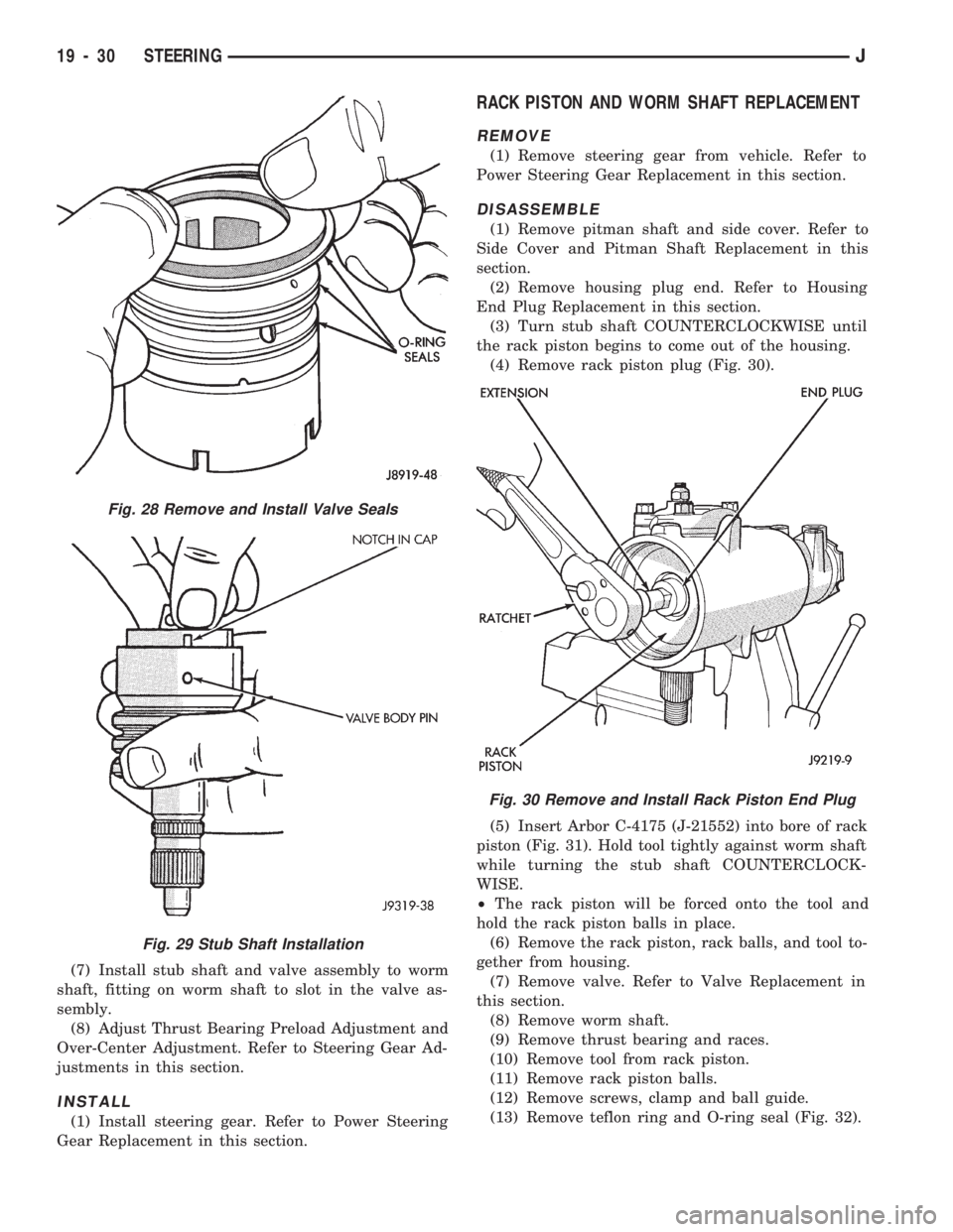
and insert pin (Fig. 29).
²Notch in stub shaft cap MUST fully engage valve
body pin and seat against valve body shoulder.
(5) Install O-ring seals and teflon rings to valve
body.
(6) Lubricate O-ring seals and teflon rings with
power steering fluid.
Fig. 24 Tighten Lock Nut
Fig. 25 Bearing, Worm and Valve Assembly
Fig. 26 Remove and Install Stub Shaft
Fig. 27 Remove and Install Spool
JSTEERING 19 - 29
Page 1067 of 1784
(7) Install stub shaft and valve assembly to worm
shaft, fitting on worm shaft to slot in the valve as-
sembly.
(8) Adjust Thrust Bearing Preload Adjustment and
Over-Center Adjustment. Refer to Steering Gear Ad-
justments in this section.
INSTALL
(1) Install steering gear. Refer to Power Steering
Gear Replacement in this section.
RACK PISTON AND WORM SHAFT REPLACEMENT
REMOVE
(1) Remove steering gear from vehicle. Refer to
Power Steering Gear Replacement in this section.
DISASSEMBLE
(1) Remove pitman shaft and side cover. Refer to
Side Cover and Pitman Shaft Replacement in this
section.
(2) Remove housing plug end. Refer to Housing
End Plug Replacement in this section.
(3) Turn stub shaft COUNTERCLOCKWISE until
the rack piston begins to come out of the housing.
(4) Remove rack piston plug (Fig. 30).
(5) Insert Arbor C-4175 (J-21552) into bore of rack
piston (Fig. 31). Hold tool tightly against worm shaft
while turning the stub shaft COUNTERCLOCK-
WISE.
²The rack piston will be forced onto the tool and
hold the rack piston balls in place.
(6) Remove the rack piston, rack balls, and tool to-
gether from housing.
(7) Remove valve. Refer to Valve Replacement in
this section.
(8) Remove worm shaft.
(9) Remove thrust bearing and races.
(10) Remove tool from rack piston.
(11) Remove rack piston balls.
(12) Remove screws, clamp and ball guide.
(13) Remove teflon ring and O-ring seal (Fig. 32).
Fig. 28 Remove and Install Valve Seals
Fig. 29 Stub Shaft Installation
Fig. 30 Remove and Install Rack Piston End Plug
19 - 30 STEERINGJ
Page 1068 of 1784
CLEAN AND INSPECTION
(1) Wash all components in clean solvent and dry
with compressed air.
(2) Check for scores, nicks or burrs on the rack pis-
ton finished surface. Slight wear is normal on the
worm gear surfaces.
ASSEMBLE
(1) Install O-ring seal and teflon ring and lubricate
with power steering fluid.
(2) Install worm shaft to rack piston outside of
housing. Fully seat worm shaft to rack piston and
align worm shaft spiral groove with rack piston ball
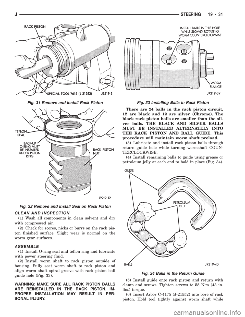
guide hole (Fig. 33).
WARNING: MAKE SURE ALL RACK PISTON BALLS
ARE REINSTALLED IN THE RACK PISTON. IM-
PROPER INSTALLATION MAY RESULT IN PER-
SONAL INJURY.There are 24 balls in the rack piston circuit,
12 are black and 12 are silver (Chrome). The
black rack piston balls are smaller than the sil-
ver balls. THE BLACK AND SILVER BALLS
MUST BE INSTALLED ALTERNATELY INTO
THE RACK PISTON AND BALL GUIDE. This
procedure will maintain worm shaft preload.
(3) Lubricate and install rack piston balls through
return guide hole while turning wormshaft COUN-
TERCLOCKWISE.
(4) Install remaining balls to guide using grease or
petroleum jelly at each end to hold in place (Fig. 34).
(5) Install guide onto rack piston and return with
clamp and screws. Tighten screws to 58 Nzm (43 in.
lbs.) torque.
(6) Insert Arbor C-4175 (J-21552) into bore of rack
piston. Hold tool tightly against worm shaft while
Fig. 34 Balls in the Return Guide
Fig. 31 Remove and Install Rack Piston
Fig. 32 Remove and Install Seal on Rack Piston
Fig. 33 Installing Balls in Rack Piston
JSTEERING 19 - 31
Page 1069 of 1784
turning the stub shaft COUNTERCLOCKWISE.
²The rack piston will be forced onto the tool and
hold the rack piston balls in place.
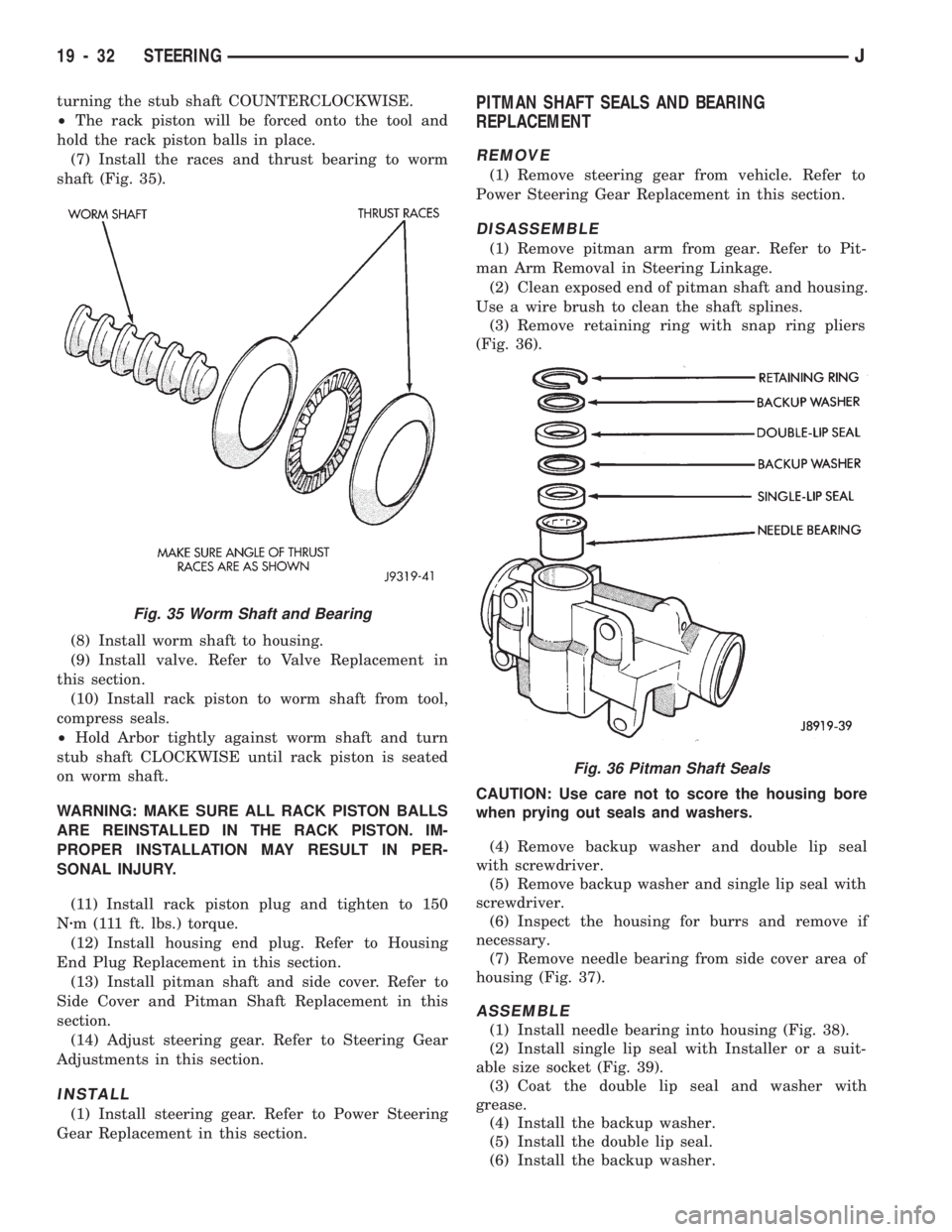
(7) Install the races and thrust bearing to worm
shaft (Fig. 35).
(8) Install worm shaft to housing.
(9) Install valve. Refer to Valve Replacement in
this section.
(10) Install rack piston to worm shaft from tool,
compress seals.
²Hold Arbor tightly against worm shaft and turn
stub shaft CLOCKWISE until rack piston is seated
on worm shaft.
WARNING: MAKE SURE ALL RACK PISTON BALLS
ARE REINSTALLED IN THE RACK PISTON. IM-
PROPER INSTALLATION MAY RESULT IN PER-
SONAL INJURY.
(11) Install rack piston plug and tighten to 150
Nzm (111 ft. lbs.) torque.
(12) Install housing end plug. Refer to Housing
End Plug Replacement in this section.
(13) Install pitman shaft and side cover. Refer to
Side Cover and Pitman Shaft Replacement in this
section.
(14) Adjust steering gear. Refer to Steering Gear
Adjustments in this section.
INSTALL
(1) Install steering gear. Refer to Power Steering
Gear Replacement in this section.
PITMAN SHAFT SEALS AND BEARING
REPLACEMENT
REMOVE
(1) Remove steering gear from vehicle. Refer to
Power Steering Gear Replacement in this section.
DISASSEMBLE
(1) Remove pitman arm from gear. Refer to Pit-
man Arm Removal in Steering Linkage.
(2) Clean exposed end of pitman shaft and housing.
Use a wire brush to clean the shaft splines.
(3) Remove retaining ring with snap ring pliers
(Fig. 36).
CAUTION: Use care not to score the housing bore
when prying out seals and washers.
(4) Remove backup washer and double lip seal
with screwdriver.
(5) Remove backup washer and single lip seal with
screwdriver.
(6) Inspect the housing for burrs and remove if
necessary.
(7) Remove needle bearing from side cover area of
housing (Fig. 37).
ASSEMBLE
(1) Install needle bearing into housing (Fig. 38).
(2) Install single lip seal with Installer or a suit-
able size socket (Fig. 39).
(3) Coat the double lip seal and washer with
grease.
(4) Install the backup washer.
(5) Install the double lip seal.
(6) Install the backup washer.
Fig. 36 Pitman Shaft Seals
Fig. 35 Worm Shaft and Bearing
19 - 32 STEERINGJ
Page 1070 of 1784
(7) Install the retainer ring with snap ring pliers.(8) Install the pitman shaft and side cover. Refer
to Side Cover and Pitman Shaft Replacement in this
section.
INSTALL
(1) Install steering gear. Refer to Power Steering
Gear Replacement in this section.
CHECK VALVE REPLACEMENT
REMOVE
(1) Remove steering gear from vehicle. Refer to
Power Steering Gear Replacement in this section.
DISASSEMBLE
CAUTION: Use care not to damage the threads of
the housing when prying out check valve.
(1) Remove valve by prying from housing with a
small screwdriver.
ASSEMBLE
(1) Install the valve into the housing with a 3/8-
inch diameter piece of tubing 100 mm (4 inches)
long.
INSTALL
(1) Install steering gear. Refer to Power Steering
Gear Replacement in this section.
Fig. 37 Needle Bearing Removal
Fig. 38 Pitman Shaft Bearing Installation
Fig. 39 Pitman Shaft Seal Installation
JSTEERING 19 - 33
Page 1071 of 1784
POWER STEERING GEAR SPECIFICATIONS
19 - 34 STEERINGJ
Page 1106 of 1784
STEERING RHD
GENERAL SERVICE PROCEDURE INFORMATION
Right hand drive service procedures and torque
specifications involving steering; linkage, gear and
column are the same as left hand drive vehicles ex-
cept where shown. Refer to appropriate service proce-
dures regarding each component in the system.
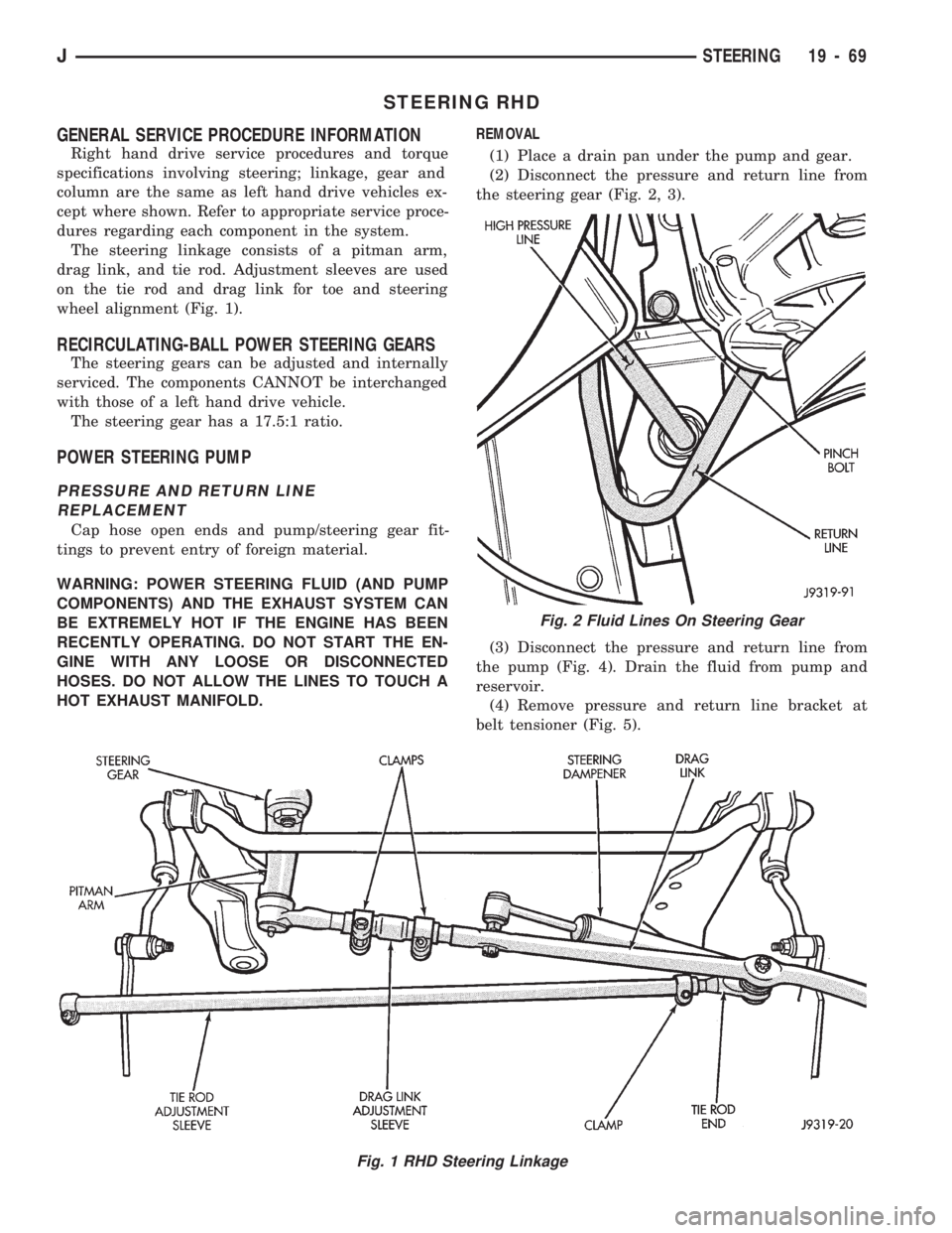
The steering linkage consists of a pitman arm,
drag link, and tie rod. Adjustment sleeves are used
on the tie rod and drag link for toe and steering
wheel alignment (Fig. 1).
RECIRCULATING-BALL POWER STEERING GEARS
The steering gears can be adjusted and internally
serviced. The components CANNOT be interchanged
with those of a left hand drive vehicle.
The steering gear has a 17.5:1 ratio.
POWER STEERING PUMP
PRESSURE AND RETURN LINE
REPLACEMENT
Cap hose open ends and pump/steering gear fit-
tings to prevent entry of foreign material.
WARNING: POWER STEERING FLUID (AND PUMP
COMPONENTS) AND THE EXHAUST SYSTEM CAN
BE EXTREMELY HOT IF THE ENGINE HAS BEEN
RECENTLY OPERATING. DO NOT START THE EN-
GINE WITH ANY LOOSE OR DISCONNECTED
HOSES. DO NOT ALLOW THE LINES TO TOUCH A
HOT EXHAUST MANIFOLD.REMOVAL
(1) Place a drain pan under the pump and gear.
(2) Disconnect the pressure and return line from
the steering gear (Fig. 2, 3).
(3) Disconnect the pressure and return line from
the pump (Fig. 4). Drain the fluid from pump and
reservoir.
(4) Remove pressure and return line bracket at
belt tensioner (Fig. 5).
Fig. 1 RHD Steering Linkage
Fig. 2 Fluid Lines On Steering Gear
JSTEERING 19 - 69