Page 445 of 521
Body Systems & Body Repair
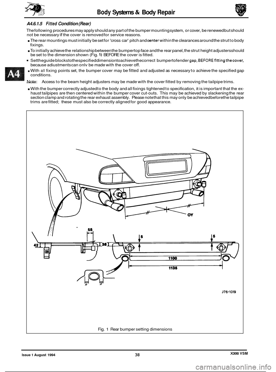
A4.2.6 CU77/NG AND WELDlNG SYMBOLS
1. SawCut
2. Chisel Cut AkAAAkAAkAA
666666@6646
4. Resistance Spot Weld 00000000000
3. Cut Out Spot Weld
5. MIG Tack Weld DmmDmm=m=
6. MIG Seam / Butt Weld BBBBBBBBBBB
7. Braze
8. Gas Weld
9. MIG Plug Weld WIIBIIBBIII
Fig. 1 Key to symbols
CAUTION: Reference should always be made to the welding tables and illustrations in the relevant procedures. Obsenfo all safety precautions with respect to yourself, other peopIe, your equipment and the workplace.
0
0
X300 VSM 18 Issue 1 August 1994
Page 464 of 521
conditions.
. Tighten all fixings to specification.
A4.6.1.3 SERVICE PROCEDURES
A4.6.1.4
Fitted Condition (Front)
The following procedures may apply should any part of the bumper mounting system, or cover, be renewed but should
not be necessary if the cover is removed for service reasons.
The front mountings must initially be set for 'cross car' pitch and center within the clearances around thestrut to body
. In orderthat the bumpertop face, headlamp surrounds and grille lower have the correct relationship the strut height
. Set the guide blocksto thespecified dimensionto achievethecorrect bumpertofender gap, BEFOREfittingthecover
. With all fixing points set, the bumper cover may be fitted and adjusted as necessary to achieve the specified gap
fixings.
adjusters must be finally
set AFTER the cover is fitted.
because adjustments can only be made with the cover
off.
Fig. 1 Front bumper setting dimensions
Issue 1 August 1994 37 X300 VSM
Page 465 of 521

Body Systems & Body Repair
A4.6.1.5 Fitted Condition (Rear)
The following procedures may apply should any part of the bumper mounting system, or cover, be renewed but should
not be necessary if the cover is removed for service reasons.
. The rear mountings must initially be set for 'cross car' pitch and center within the clearances around the strut to body
. To initially achieve the relationship between the bumpertop face and the rear panel, the strut height adjustersshould
9 Settheguide blockstothespecified dimensiontoachievethecorrect bumpertofender gap,BEFOREfittingthecover,
fixings.
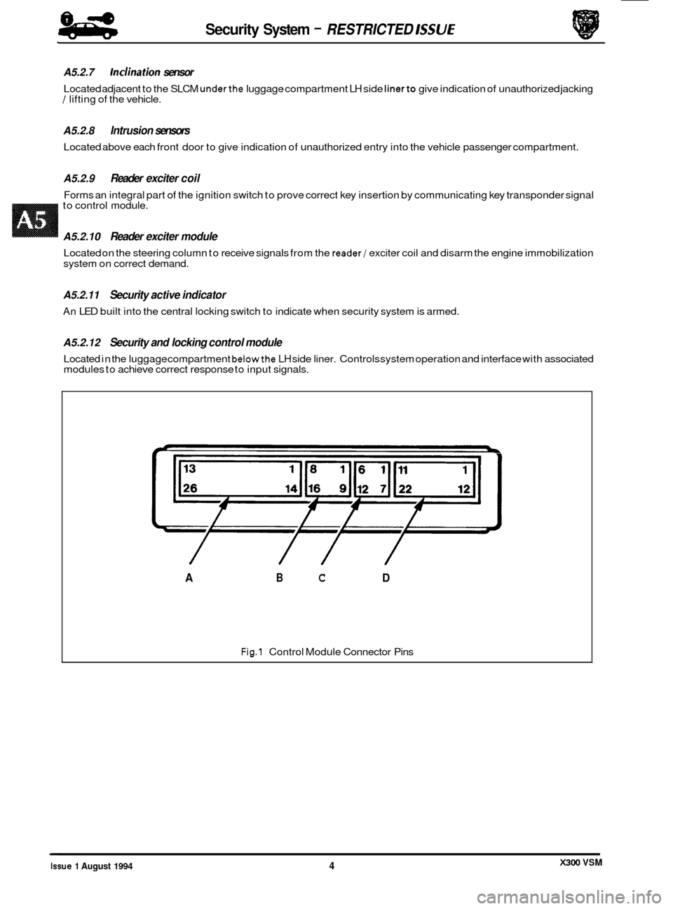
be set to the dimension shown (Fig.
1) BEFORE the cover is fitted.
because adiustments can onlv be made with the cover
off.
. With all fixing points set, the bumper cover may be fitted and adjusted as necessary to achieve the specified gap
- Note:
conditions.
Access to the beam height adjusters may be made with the cover fitted by removing the tailpipe trims.
. With the bumper correctly adjusted to the body and all fixings tightened to specification, it is important that the ex-
haust tailpipes are then centered within the bumper cover cut-outs. This may be achieved by slackening the rear
section clamp and rotating the rear exhaust assembly. Please note that this may only be achieved before the tailpipe
trims are fitted; these must also be correctly aligned for good appearance.
J76-1019
Fig. 1 Rear bumper setting dimensions
X300 VSM Issue 1 August 1994 38
Page 481 of 521

84
- Security System - RESTRICTED /SSU€
A5.2.7 Inclination sensor
Located adjacent to the SLCM underthe luggage compartment LH side linerto give indication of unauthorized jacking / lifting of the vehicle.
A5.2.8 Intrusion sensors
Located above each front door to give indication of unauthorized entry into the vehicle passenger compartment.
A5.2.9 Reader exciter coil
Forms an integral part of the ignition switch to prove correct key insertion by communicating key transponder signal
to control module.
A5.2.10 Reader exciter module
Located on the steering column to receive signals from the reader/ exciter coil and disarm the engine immobilization
system on correct demand.
A5.2.11 Security active indicator
An LED built into the central locking switch to indicate when security system is armed.
A5.2.12 Security and locking control module
Located in the luggage compartment belowthe LH side liner. Controls system operation and interface with associated
modules to achieve correct response to input signals.
L
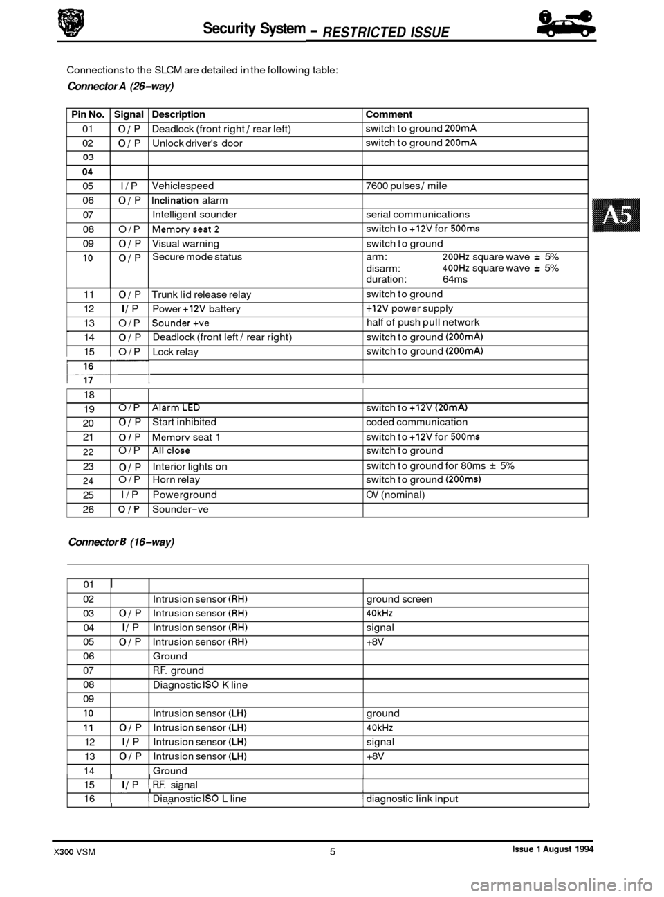
Fig.1 Control Module Connector Pins
/ // /
A B C D
X300 VSM Issue 1 August 1994 4
Page 482 of 521

Security System
Pin No. Signal Description
01 0 / P Deadlock (front right / rear left)
02
0 / P Unlock driver's door
03
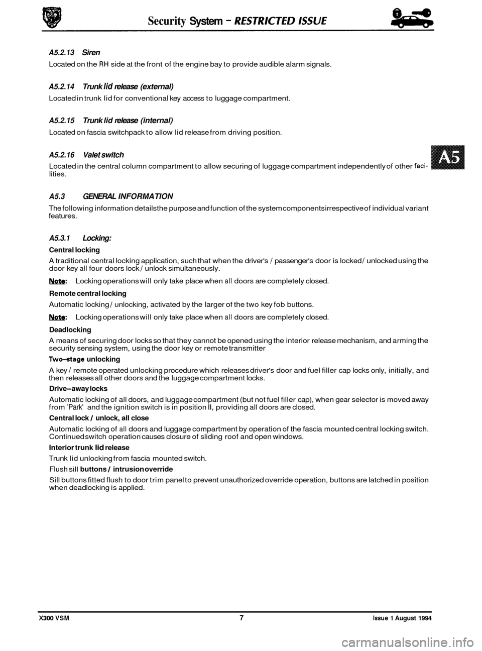
Connections to the SLCM are detailed in the following table:
9 Connector A (26-way)
Comment
switch to ground 200mA
switch to ground 200mA
05 I/P
06
0 / P
07
08 O/P
09
0 / P
10 0 / P Vehiclespeed
7600 pulses
/ mile
Inclination alarm
Intelligent sounder serial communications
Memoryseat2
Visual warning switch to ground
Secure mode status arm:
200Hz square wave f 5%
400Hz square wave f 5%
switch
to
+12V for 500ms
disarm:
duration: 64ms
0
117- I I
11 0 / P Trunk lid release relay 1 switch to ground
12
I / P Power +12V battery 1 + 12V power supply
13 O/P
Sounder+ve half of push pull network
14
0 / P Deadlock
(front left / rear right) switch to ground (200mA)
15 O/P Lock relay switch
to ground (200mA)
18
19
20 21 O/P
AlarmLED switch
to +12V (20mA)
0 / P Start inhibited coded communication
0 / P Memorv seat 1 switch
to +12V for 500ms
Connector 8 (16-way)
22
23
24
25
26 O/P
Allclose switch
to ground
0 / P
O/P Horn relay switch to ground
(200ms)
I/P Powerground OV (nominal)
OJP Sounder-ve
Interior lights
on switch
to ground for 80ms
f 5%
01
I
02
03 04
05
06
07
08
09
I I I I 15 I I / P I R.F. sianal
Intrusion
sensor
(RH) ground screen
0 / P Intrusion sensor (RH) 40kHz
I / P Intrusion sensor (RH) signal
0 / P Intrusion sensor (RH) +8V
Ground
R.F. ground
Diagnostic
IS0 K line
I. I - I 16 I I Diaanostic IS0 L line 1 diagnostic link input
10
11
12
13
14
.I
I I" 1- I
Intrusion sensor (LH) ground
0 / P Intrusion sensor (LH) 40kHz
I / P Intrusion sensor (LH) signal
0 / P Intrusion sensor (LH) +8V
Ground
Issue 1 August 1994 X300 VSM 5
84
- RESTRICTED ISSUE -
Page 484 of 521

lities.
A5.3 GENERAL INFORMATION
The following information detailsthe purpose and function of the system components irrespective of individual variant
features.
A5.3.1 Locking:
Central locking
A traditional central locking application, such that when the driver's / passenger's door is locked / unlocked using the
door key all four doors lock / unlock simultaneously.
1ynfe: Locking operations will only take place when all doors are completely closed.
Remote central locking
Automatic locking / unlocking, activated by the larger of the two key fob buttons.
1ynfe: Locking operations will only take place when all doors are completely closed.
Deadlocking
A means of securing door locks so that they cannot be opened using the interior release mechanism, and arming the
security sensing system, using the door key or remote transmitter
Two-otage unlocking
A key / remote operated unlocking procedure which releases driver's door and fuel filler cap locks only, initially, and
then releases all other doors and the luggage compartment locks.
Drive-away locks
Automatic locking of all doors, and luggage compartment (but not fuel filler cap), when gear selector is moved away
from 'Park' and the ignition switch is in position II, providing all doors are closed.
Central lock / unlock, all close
Automatic locking of all doors and luggage compartment by operation of the fascia mounted central locking switch.
Continued switch operation causes closure of sliding roof and open windows.
Interior trunk lid release
Trunk lid unlocking from fascia mounted switch.
Flush sill buttons / intrusion override
Sill buttons fitted flush to door trim panel to prevent unauthorized override operation, buttons are latched in position
when deadlocking is applied.
Security System - RESTRKTED lSSUE
A5.2.13 Siren
Located on the RH side at the front of the engine bay to provide audible alarm signals.
A5.2.14 Trunk lid release (external)
Located in trunk lid for conventional key access to luggage compartment.
A5.2.15 Trunk lid release (internal)
Located on fascia switchpack to allow lid release from driving position.
A5.2.16 Valet switch
Located in the central column compartment to allow securing of luggage compartment independently of other faci-
X300 VSM 7 Issue 1 August 1994
Page 504 of 521
0
1
AS. 9.3 Door locks
U 1. Check harness wiring continuity between multi-plug 12-way connector pins 10 (driver's side)
and
4 (passenger's side) to respective door lock connector pin 8. Ensure secure ground
connection from each lock connector pin
9.
Test continuity across switch pins, reading should be open circuit with door unlocked, short
circuit with door locked. 2.
7 e-----
I I I
1 r
I-, -a
.-
mT
YB .
mcE?-l
YR
7 7 p-ww--
I I I
) ,
1
JBB-1908
I Fig. 1 Door Locks Circuit
9 J
3
X300 VSM 27 Issue 1 August 1994
Page 507 of 521
Security System - RESTRICTED ISSUE
AS. 9.6 Horns
1.
2.
Check fuses FIO and F14 in LH engine bay fuse box; if blown determine reason for rupture and
renew.
Check wiring harness continuity from multi
-plug 26-way connector pin 24 to relay unit
connector pin
6 and column switchgear connector pin 16. Ensure secure ground connection
from column switchgear connector pin
7.
Check wiring harness continuity from fuse connector pins 7 and 8 to LH and RH horn
respectively. Ensure secure ground connection from both horn units.
Ensure that
+12V (nominal) is present at the relay connector pin.
Operate horn switches and check that
+12V (nominal) is present at the two fuse connector pins
and
at speaker connector pin 44 (both units).
Check resistance across speaker unit pins;
a value of approximately 2Q should be recorded.
P21.
1
r- I
$ I
I
I
I I I,, Fu
0
J86- 1911
Fig. 1 Horn Unit and Relay Circuit
X300 VSM Issue 1 August 1994 30