1994 JAGUAR XJ6 climate control
[x] Cancel search: climate controlPage 89 of 327

Climate Control Systems
14.7.2 Fault Code 12
Ambient Temperature Sensor
0 Sensor, harness or A 1 CCM open circuit.
0 Sensor, harness or A 1 CCM short circuit to ground.
If the signal on pin 27 (12-way connector, AI CCM) remains at less than 1 volt, suspect either a short circuit to ground
on the signal wire or an open circuit on the 5 volt supply to the sensor. If the signal on pin 27 rises to approximately 5 volts, suspect an open circuit on the earth supply to the sensor.
Checkthe voltage, against the graph below (Fig. I), measured between pin 27 (12-way connector) and pin 19 (22-way
connector) A 1 C CM.
If the voltage is within the set limits, the system is operating correctly.
A resistance check can be carried out on the sensor and should conform with the figures below, measured between
pin 27 (12-way connector) and pin 19 (22-way connector) AI CCM.
10°C 3.1
- 3.7 w1 25°C 1.6- 1.8 w1 50°C 0.5 - 0.7 w1
If the resistance is outside the set limits, renew the sensor.
Nnfe:
Inspect sensor harness for open circuit or short circuit to ground. Rectify as necessary.
If the voltage is outside the set limits, renew the AI CCM.
The resistance
should continue to decrease as the temperature increases and vice versa.
80
70
80
50
40
30
OC 20
10
0
-10
- 20
- 30
- 40
V
Fin. 1
J86 -17'38
0
0
0
0
Issue 1 August 1994 14 X300 EDM
Page 90 of 327

Climate Control Systems
14.7.3 Faultcode 13
Evaporator Temperature Sensor
0 Sensor, harness or A / CCM open circuit.
0 Sensor, harness or A/ CCM short circuit to ground.
This sensor monitors the temperature of the evaporator matrix, the output is used to trigger the compressor circuit
via the
A/ CCM pin 34 (12-way connector).
If the signal on pin 34 (12-way connector) remains at less than 1 volt, suspect either a short circuit to ground on the
signal wire or an open circuit on the 5 volt supply to the sensor. If the signal on pin 34 rises to approximately 5 volts
then suspect an open circuit on the sensor ground.
Checkthe voltage, against the graph below (Fig. I), measured between pin 34 (12-way connector) and pin 19 (22-way
connector) A / C CM.
If the voltage is within the set limits, the system is operating correctly.
A resistance check can be carried out on the sensor and should conform with the figures below, measured between
pin 34 (12
-way connector) and pin 19 (22-way connector) A / C CM.
0°C
4.6- 5.1 WZ
15°C 2.1 - 2.6 WZ
If the resistance is outside the set limits, renew the sensor.
Note:
Inspect sensor harness for open circuit or short circuit to ground. Rectify as necessary.
If the voltage is outside the set limits, renew the
A/ CCM.
The resistance should continue to decrease as the temperature increases and vice versa.
*C
J86-1769
Fig. 1
X300 EDM 15 Issue 1 August 1994
Page 91 of 327

Climate Control Systems
14.7.4 Fault Code 14
Coolant Temperature
Input
0 Sensor, harness or A / CCM open circuit.
0 Sensor, harness or A / CCM short circuit to ground.
This input is derived from the instrument pack,
a continuity check can be carried out from pin 22, instrument pack (24-wayconnector), to pin 40 (16-way connector) of the A / C CM.
The instrument pack input from the engine coolant temperature sensor, is covered in the EDM, section 15, Instrument
Pack and Trip Computer.
14.7.5 Fault Code 15
Heater Matrix Temperature Sensor
0 Sensor, harness or A/ CCM open circuit.
0 Sensor, harness or A / CCM short circuit to ground.
This sensor measures the temperature of the heater matrix.
If the signal on pin 28 (12-way connector) remains at less than 1 volt, suspect either a short circuit to ground on the
signal wire or an open circuit on the 5 volt supply to the sensor. If the signal on pin 28 rises to approximately 5 volts
then suspect an open circuit on the sensor ground.
Checkthevoltage, against the graph below (Fig.
I), measured between pin 28 (12-way connector) and pin 19 (22-way
connector) A / C CM.
If the voltage is within the set limits, the system is operating correctly.
A resistance check can be carried out on the sensor and should conform with the figures below, measured between
pin 28 (12-way connector) and pin 19 (22-way connector) A/ C CM.
0°C 4.6
-5.1 lclL 15°C 2.1 - 2.6 lclL
If the resistance is outside the set limits, renew the sensor.
1ynfe:
Inspect sensor harness for open circuit or short circuit to ground. Rectify as necessary.
If the voltage is outside the set limits, renew the A / CCM.
The
resistance should continue to decrease as the temperature increases and vice versa.
*C
V
J86-1771
Fig.
Issue 1 August 1994 16 X300 EDM
Page 92 of 327

Climate Control Systems
14.7.6 FaulfCode21
Solar Sensor
0 Sensor, harness or A / CCM open circuit.
0 Sensor, harness or A / CCM short circuit to ground.
The sensor provides a linear output response signal to
pin 35 (16-way connector) A/ CCM; the output ranges from 0 to 5 volts, the voltage will drop as light intensity increases.
A resistance check can be carried out on the sensor and should conform with the figures below:
With no light on the sensor, the resistance should read approximately 15
kL2.
With increasing light intensity, the resistance should decrease from 15 kQ.
Inspect the sensor harness for open circuit or short circuit to ground. Rectify as necessary.
If the sensor and harness appear correct, suspect the A/ CCM.
14.7.7 Fadf Code 22
Compressor lock Signal
(12 cy/. vehicles only)
0 Sensor, harness or A / CCM open circuit.
0 Sensor, harness or A/ CCM short circuit to ground.
The compressor lock sensor provides an
a.c. signal proportional to engine speed. As engine speed increases the a.c. signal voltage value will increase.
A voltage checkcan be carried out on the sensor and should read approximately 0.5V a.c. whilst the compressor is ON and OV whilst the compressor is OFF, measured between pin 26 (12-way connector) and pin 19 (22-way connector) A
/ C CM.
If the reading is OV whilst the compressor is ON, suspect the sensor or the sensor harness (open circuit or short circuit
to ground).
Check the resistance between pins 1 and 2 of the compressor lock sensor, value should be
190a & 20%.
If the resistance measured falls outside the limits, renew the compressor lock sensor.
Inspect the sensor harness for open circuit or short circuit to ground. Rectify as necessary.
If the sensor and harness appear correct, suspect the AI CCM.
X300 EDM 17 Issue 1 August 1994
Page 93 of 327

Climate Control Systems
Minimum differential (Red)
Maximum differential (Blue)
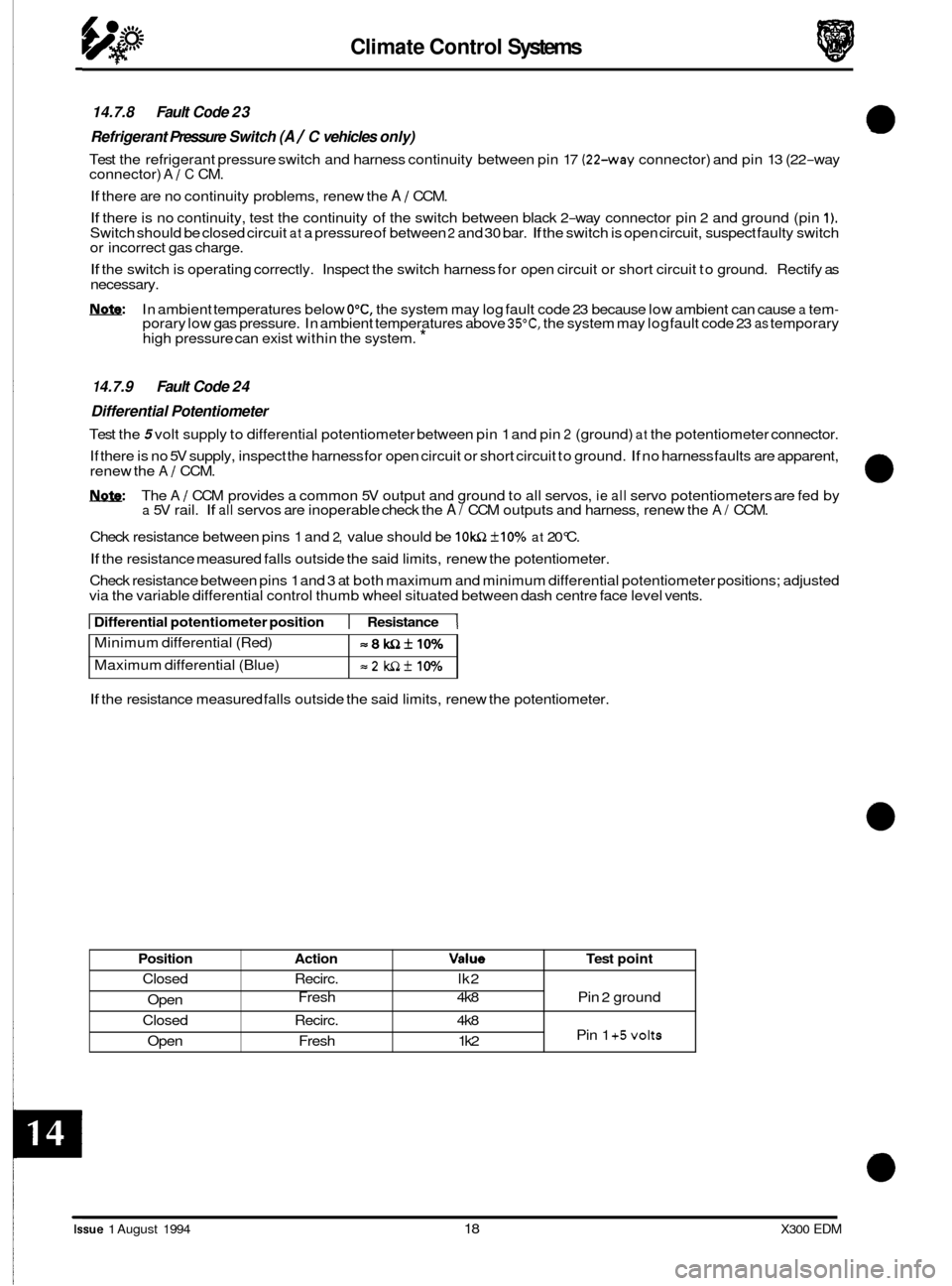
14.7.8 Fault Code 23
Refrigerant Pressure Switch
(A / C vehicles only)
Test the refrigerant pressure switch and harness continuity between pin 17 (22-way connector) and pin 13 (22-way
connector) A / C CM.
If there are no continuity problems, renew the A / CCM.
If there is no continuity, test the continuity of the switch between black 2-way connector pin 2 and ground (pin 1). Switch should be closed circuit at a pressure of between 2 and 30 bar. If the switch is open circuit, suspect faulty switch
or incorrect gas charge.
If the switch is operating correctly. Inspect the switch harness for open circuit or short circuit to ground. Rectify as
necessary.
Nnfe: In ambient temperatures below O"C, the system may log fault code 23 because low ambient can cause a tem- porary low gas pressure. In ambient temperatures above 35"C, the system may log fault code 23 as temporary
high pressure can exist within the system. *
=8WZkIO%
=2 WZf 10%
1 4.7.9 Fault Code 24
Differential Potentiometer
Test the 5 volt supply to differential potentiometer between pin 1 and pin 2 (ground) at the potentiometer connector.
If there is no 5V supply, inspect the harness for open circuit or short circuit to ground.
If no harness faults are apparent,
renew the A / CCM.
1ynf9: The A / CCM provides a common 5V output and ground to all servos, ie all servo potentiometers are fed by a 5V rail. If all servos are inoperable check the A/ CCM outputs and harness, renew the A/ CCM.
Check resistance between pins 1 and
2, value should be IOWZ +10% at 20°C.
If the resistance measured falls outside the said limits, renew the potentiometer.
Check resistance between pins 1 and 3 at both maximum and minimum differential potentiometer positions; adjusted
via the variable differential control thumb wheel situated between dash centre face level vents.
Position
Closed
Open
Closed
Open
I Differential potentiometer position 1 Resistance 1
Action Value Test point
Recirc. lk2
Fresh 4k8 Pin 2 ground
Recirc. 4k8
Pin
1 +5volts Fresh 1 k2
If the resistance measured falls outside the said limits, renew the potentiometer.
a
0
0
Issue 1 August 1994 18 X300 EDM
Page 94 of 327

Climate Control Systems
Position
Closed Open
Closed Open
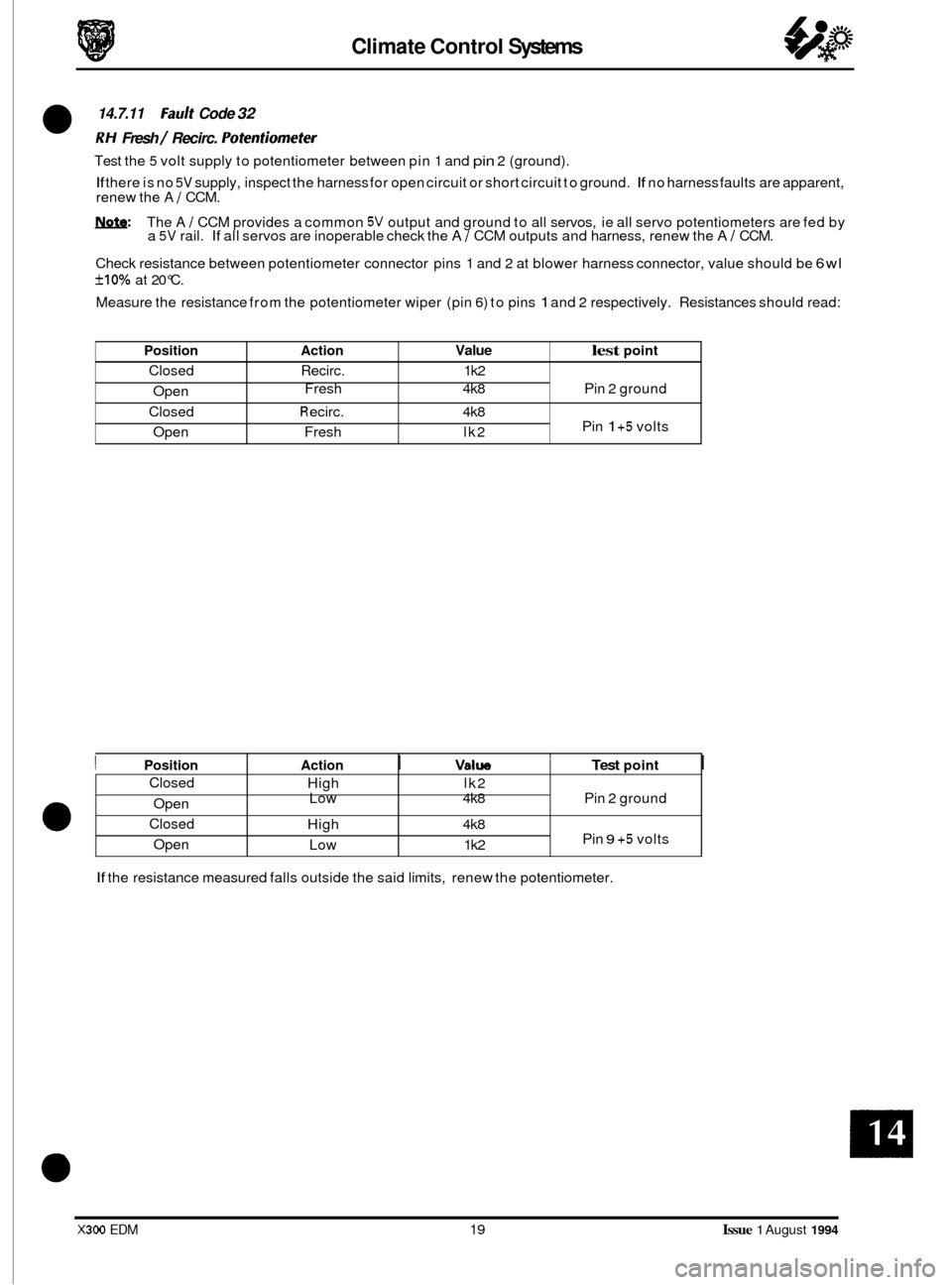
14.7.11 Fault Code 32
RH Fresh / Recirc. Pofenfiomefer
Test the 5 volt supply to potentiometer between pin 1 and pin 2 (ground).
If there is no 5V supply, inspect the harness for open circuit or short circuit to ground. If no harness faults are apparent,
renew the A 1 CCM.
W: The A / CCM provides a common 5V output and ground to all servos, ie all servo potentiometers are fed by
a 5V rail. If all servos are inoperable check the A 1 CCM outputs and harness, renew the A I CCM.
Check resistance between potentiometer connector pins 1 and 2 at blower harness connector, value should be
6wl
f10% at 20°C.
Measure the resistance from the potentiometer wiper (pin
6) to pins 1 and 2 respectively. Resistances should read:
Action Value lest point
Recirc. 1 k2
Fresh 4k8 Pin 2 ground
R eci rc. 4k8
Pin 1 +5 volts
Fresh lk2
Closed Open
Closed
Open
e
I Position I Action I Valw 1 Test point I
High lk2
Low 4k8 Pin 2 ground
High 4k8
Pin
9 +5 volts
Low 1 k2
If the resistance measured falls outside the said limits, renew the potentiometer.
X300 EDM 19 Issue 1 August 1994
Page 95 of 327

Climate Control Systems
Position
Closed
Open
Closed
ODen
14.7.13 Fault Code 34
Defrost
Vent Potentiomefer
Disconnect the CENTRE VENT servo yellow, Sway connector.
Test the 5V supply to the potentiometer at the air distribution connector (black 12-way), pin 9 (positive) and pin 2
If there is no 5 volt supply, inspect the harness for open circuit or short circuit to ground. If no harness faults are appar-
ent, renew the A / CCM.
&&: The A / CCM provides a common 5V output and ground to all servos, ie all servo potentiometers are fed by a 5V rail. If all servos are inoperable check the A/ CCM outputs and harness, renew the AI CCM.
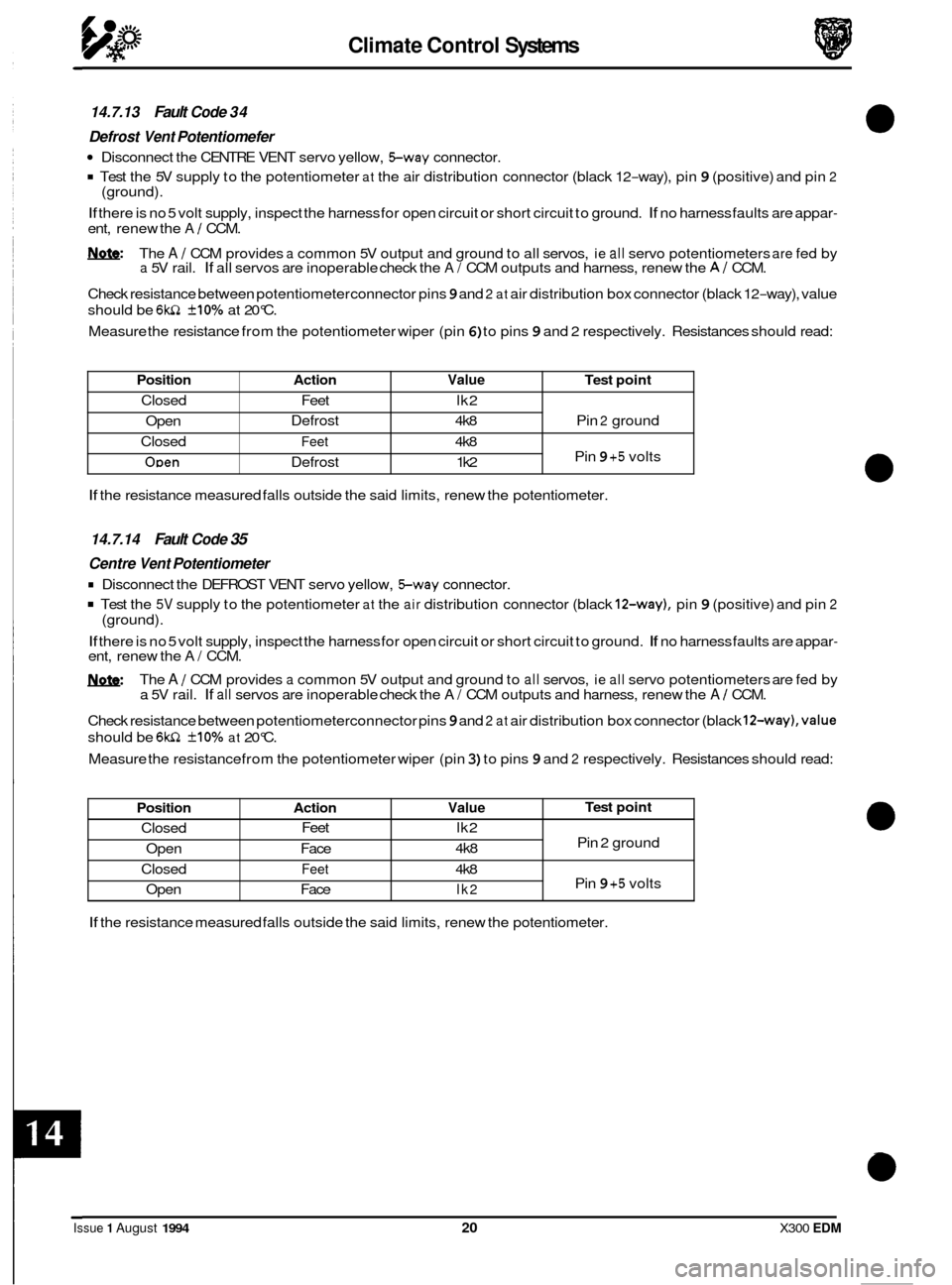
Check resistance between potentiometer connector pins
9 and 2 at air distribution box connector (black 12-way), value
should be
6w1 +10% at 20°C.
Measure the resistance from the potentiometer wiper (pin
6) to pins 9 and 2 respectively. Resistances should read:
(ground).
Action Value Test
point
Defrost 4k8 Pin 2 ground
Feet 4k8
Pin 9 +5 volts
Defrost 1 k2
Feet
lk2
Position Action Value
Closed Feet
lk2
4k8
Open Face
Closed
Feet 4k8
Open Face
lk2
If the resistance measured falls outside the said limits, renew the potentiometer.
Test point
Pin 2 ground
Pin
9 +5 volts
14.7.14 Fault Code 35
Centre Vent Potentiometer
Disconnect the DEFROST VENT servo yellow, Sway connector.
Test the 5V supply to the potentiometer at the air distribution connector (black 12-way), pin 9 (positive) and pin 2
If there is no 5 volt supply, inspect the harness for open circuit or short circuit to ground. If no harness faults are appar- ent, renew the A/ CCM.
The
A / CCM provides a common 5V output and ground to all servos, ie all servo potentiometers are fed by
a 5V rail. If all servos are inoperable check the A/ CCM outputs and harness, renew the A / CCM.
Check resistance between potentiometerconnector pins
9 and 2 at air distribution box connector (black 12-way),value
should be 6wZ +10% at 20°C.
Measure the resistance from the potentiometer wiper (pin
3) to pins 9 and 2 respectively. Resistances should read:
(ground).
If the
resistance measured falls outside the said limits, renew the potentiometer.
Issue 1 August 1994 20 X300 EDM
Page 96 of 327

Climate Control Systems
Position Action Value Test point
Closed Face 1 k2
Open Foot
4k8
Closed Face
4k8
Open Foot
1 k2
Pin 2 ground
Pin
9 +5 volts
14.7.15 Fault Code 36
Foot Vent
Potentiometer
Disconnect the COOL AIR BYPASS yellow, Sway connector.
. Test the 5V supply to the potentiometer at the main unit, pin 9 (positive) and pin 2 (ground).
If there is no 5 volt supply, inspect the harness for open circuit or short circuit to ground. If no harness faults are appar- ent, renew the A I CCM.
&&: The A I CCM provides a common 5V output and ground to all servos, ie all servo potentiometers are fed by a 5V rail. If all servos are inoperable check the A 1 CCM outputs and harness, renew the A 1 CCM.
Check resistance between potentiometer connector pins9 and
2 at blower motor connector, value should be 6kn +10%
at 20°C.
Measure the resistance from the potentiometer wiper (pin
6) to pins 9 and 2 respectively. Resistances should read:
14.7.16 Fault Code 4 1
1 H Fresh / Recirc. Motor
The resistance between pins 1 and 3, servo unit Sway connector, should read 4.8 - 7.2 kn.
If the resistance is outside of the set limits, renew the servo unit.
The motor operation can be checked by applying battery voltage to pin
5, motor %way connector, and ground to pin 4 of the connector. The motor arm should rotate smoothly in a clockwise direction. Renew the motor if the arm does
not rotate smoothly.
Apply battery voltage to pin
4, servo unit %ay connector, and ground to pin 5. The motor arm should rotate smoothly
in a anti-clockwise direction. Renew the motor if the arm does not rotate smoothly.
Inspect the harness for open circuit or short circuit to ground. Rectify as necessary.
If no harness faults are apparent,
renew the AI CCM.
14.7.17 Fault Code 42
RH Fresh / Recirc. Motor
The resistance between pins 1 and 3, servo unit Sway connector, should read 4.8 - 7.2 kn.
If the resistance is outside of the set limits, renew the servo unit.
The motor operation can be checked by applying battery voltage to pin
5, motor Sway connector, and ground to pin 4 of the connector. The motor arm should rotate smoothly in a clockwise direction. Renew the motor if the arm does
not rotate smoothly.
Apply battery voltage to pin
4, servo unit Sway connector, and ground to pin 5. The motor arm should rotate smoothly
in a anti-clockwise direction. Renew the motor if the arm does not rotate smoothly.
Inspect the harness for open circuit or short circuit to ground. Rectify as necessary.
If no harness faults are apparent,
renew the A I CCM.
21 Issue 1 August 1994