Page 49 of 74
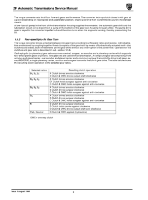
ZF Automatic Transmissions Service Manual
1
1
33
2
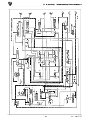
A. C1 Clutch valve
B. 2-3 shift valve piston C. C clutch damper valve D. B clutch damper E. 1-2 shift valve piston F. D clutch valve and piston
G. Pressure regulating valve
H. Manual (selector) valve I. A clutch damper J. 1-2 shift valve K. B clutch damper valve L. C clutch damper
M. 2-3 shift valve N. Converter pressure valve
!!Me: Numerical annotations are not used in this application.
Fig. 1 Manual Valve Block
&
JLL-699
Issue 1 August 1994 43
Page 50 of 74
ZF Automatic Transmissions Service Manual
2 1.
I
Jh
A. One way valve (lubrication) B. 2nd gear inhibit valve C. F clutch damper D. F clutch inhibit valve (reverse) E. 3-4 shift valve piston
F. 3-4 shift valve G. 1st gear inhibit valve H. F clutch valve
I. E clutch damper
J. C1 clutch damper
IWQ: Numerical annotations are not used in this application.
Fig.
1 Rear Valve Block
70
44 Issue 1 August 1994
Page 51 of 74
ZF Automatic Transmissions Service Manual
3
C
? a
12 L?-'
A. Modulator valve B. Kick-down valve C. Reverse inhibit valve
Note: Numerical annotations are not used in this application.
s
JbI-701
Fig. 1 Throttle Valve Block
Issue 1 August 1994 45
Page 52 of 74

4
AFLR M- -1
4 13 9
14
15 7
J44-718
1.
Selector 2. Mode switch 3. Rotary switch
4. Transmission control unit 5. Output shaft speed sensor 6. Kick-down switch 7. Battery
8. Transmission relay
9.
10.
11.
12.
13.
14.
15.
16.
Transmission control module (TCM)
Reverse lamps
Start inhibiter
Engine speed
Ignition retard
Engine load
Engine control module
(ECM) Engine speed sensor
Fig.
1 Control Layout Schematic
2.1.5 Transmission Control Module (TCM)
The Transmission Control Module (TCM) is an electronic control unit located in the front passenger footwell behind
the underscuttle pad. It is electrically connected to the transmission and other components through a cable harness
and multiple pin plug.
The TCM continuously monitors the gear selected (via the rotary transmission switch), the speed of the output shaft
(by speed sensor on the output shaft) and throttle position ('kick
-down' switch). This information plus input from the
Engine Control Module (ECM) of throttle angle and engine speed and load in conjunction with a pre-programmed con- trol map, enables the most suitable gear to be selected.
The TCM, by operating solenoid valves
MVI, MV2 and MV3, controls the gear shift speed and in conjunction with the
solenoid operated pressure control valve, controls the gear shift quality. Gear shift quality on upshifts is improved by
the TCM momentarily retarding the ignition to reduce the torque input as the gear change takes place. Information
is fed to the TCM from sensors and
if any electronic component fails, the basic shift changes will be performed by the
hydro-mechanical system, ie Park, Reverse, Neutral, D3 or D4.
46
Issue 1 August 1994
Page 53 of 74

ZF Automatic Transmissions Service Manual
Vehicle speed sensor plus input
Engine speed input
Program switch input
Solenoid valve
MVI output
Pressure control valve PCV output
?. 1.13 Harness Connections
3&31 not used
32
33 Position code
Z input
38 Torque
reduction
T (I) output
34
-37 not used
Vehicle speed sensor minus input
37
55
not used
\I
41 I Kick down switch input
J" i"
Diagnostic L-line
Transmission malfunction indicator lamp
output
not used
Solenoid valves plus input
Vehicle speed sensor screen
Engine torque signal
T(T) input
I IU,MW II
43 not used
44 Oil temperature sensor ground
45 not used
46
Oil temperature sensor input
47 Throttle position input
48 not used
I
not used
Solenoid valve
MV2 output
not used
Power ground input 19
49 Sport mode indicator output
50 Position code X input
51 Diagnostics K
-line
52
-55 not used
J86 I I69 1
Fig.
1 Transmission Control Module Connections - Pin Locations
I1
12
13
: I
17-18
22
-23
t 27-28
25
26
Function I Pin I Function I
Power supply input I 29 I Program switch /Traction control input I
Digital ground input I 39-40 lnot used I
not used
-~
48 Issue 1 August 1994
Page 54 of 74
ZF Automatic Transmissions Service Manual
N
B
W
K
G
R
2.1.14 Rotary Switch Harness
Brown Y Yellow
Black
0 Orange
White
S Slate
Pink
L Light
Green
P Purple
Red
U Blue
Fig.
1 Transmission Connector (%way)
temperature
sensor
Color Code
I I /Indigo II I
Issue 1 August 1994 49
Page 55 of 74
ZF Automatic Transmissions Service Manual
1B
28
3B
4B
58
6B
78
88
2.1.15 Main harness connectors - 12 way & 8 way
1 .o Solenoids output
1
.o MV1 solenoid
1
.o MV2 solenoid
1 .o MV WK solenoid
0.5 Pressure regulator
0.5 Start inhibit output
0.5 Start inhibit ground
0.5 Reverse lights output
Function /Pin 1::;2) [
Function /Pin I;::2) 1
U J44-704
6
12
Fig. 1 Main Harness Connector - 12 way
V J44-705
Fig. 2 Main Harness Connector - &way
Issue 1 August 1994 50
Page 56 of 74

1. 2.
3. 4.
5. 6.
7.
8. 9. 10. 11. 12. 13")
ZF Automatic Transmissions Service Manual
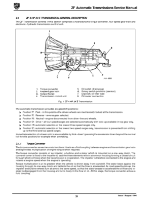
2.2 HYDRAULIC CIRCUIT DIAGRAMS
Component Engagement
Key
To Hydraulic Diagrams (commencing on page 52)
1. 2.
3. 4.
5. 6.
7.
8. 9. 10. 11. 12. 13.
14. 15. 16.
17.
18.
Oil pump Sump
Torque converter
Olil cooler
Clutch 'A' damper
Clutch 'B' valve and damper
Clutch 'Cl' damper
Clutch 'Cl' valve
Clutch 'C' valve and damper
Clutch
'D' valve and damper
Clutch 'E' damper
Clutch
'F' valve and damper
Reverse locking valve
Shift valve
1 - 2
Shift valve 2 - 3
Shift valve 3 - 4
Safety valve
Pressure valve
1
A Clutch 'A' D Clutch 'D B Clutch 'B' E Clutch 'E'
C Clutch 'C' F Clutch 'F'
C1 Clutch 'C"
19.
20.
21.
22.
23. 24.
25.
26.
27.
28.
29.
30.
31.
32.
33. 34.
35.
G
H J K
Pressure valve 2
Torque converter pressure valve
Lubrication valve
Lubrication valve
Lock
-up control valve
Modulation pressure valve
Main pressure valve
Gear change valve
Solenoid valves
MVllMV2l MV3
Pressure regulator
ECM
- inputs and outputs
Engine torque
Throttle valve Engine speed
(RPM) Transmission speed (RPM) Transmission rotary switch
Oil filter
Torque converter freewheel
(C) Clutch freewheel (D) Clutch freewheel (E) Clutch freewheel
Exhaust - Reduced pressure
=X= Th rott le - Modulation pressure
4= Orifice 2- Sump
- Main pressure - Lubrication pressure
- Converter pressure
Throttle pressure
Issue 1 August 1994 51


 B. 2nd gear inhibit valve C. F clutch damper D. F clutch inhibit valve (reverse) E. 3-4 shift valve piston")


