Page 9 of 74

ZF Automatic Transmissions Service Manual
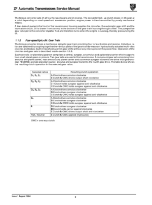
Valve
Reverse Gear
Clutches 'B','D' and 'E' are
engaged.
As the front planet gear carrier of epicyclic gear set
'1' is
locked, the direction of output shaft rotation is reversed.
Epicyclic gear set
'2' also rotates as a solid block.
Summary of function
J4L-698
Fig. 1
Pressure regulating
1-2 shift valve
2
-3 shift valve
1.1.4
This housing contains the output shaft and speed governor and the parking lock mechanism. The governor comprises
two spring loaded valves, a spindle and a weight; the governor is influenced by centrifugal and hydraulic forces and
supplies a varying hydraulic pressure.
The parking lock pawl operates on
a toothed wheel attached to the output shaft speed governor; the mechanism is
operated from the selector (position 'I") by actuator rod.
Transmission Output Shaft Extension Housing
Varies line pressure as required
Line pressure to
C & C1 clutch valves and dampers
Line pressure to
C1 clutch (2nd); line pressure to B clutch (3rd)
1.1.5 Transmission Control Unit
The hydraulic control unit comprising a series of valve blocks housing the manual (selector) valve, control pistons and
pressure valves, is attached to the underside of the transmission housing; the unit controls the operation of the gear
train clutches and directs oil pressure to the appropriate system components (refer to illustrations, pages 5 to 7 ) to
operate the transmission. The valve blocks are connected to a main gallery plate.
Line pressure from the hydraulic pump is supplied initially to the pressure regulating valve, manual valve, governor,
3
-4 shift valve, 'E' clutch and damper, throttle valve, modulator valve and torque converter pressure (and reversing)
valve. The function of each of the valves in the control unit and the governor valve is summarised in the table below.
2nd gear inhibit
3
-4 shift valve
Throttle valve
Modulator
Converter
& Reversing
Reverse inhibit
F Clutch inhibit
Converter clutch hysteresis
Converter clutch lock
-up
Converter clutch damper
Clutch valves
& Dampers
Governor Line pressure
to 2
-3 shift valve
Line pressure to
E clutch (3rd); line pressure to F clutch (4th)
Throttle pressure to modulator and shift valves
Modulated throttle pressure fed to clutch dampers and valves
Line pressure to lock
-up clutch; lubrication oil to cooler
Line pressure to B
& D clutches
Governor pressure to 3
-4 shift valve inhibited in reverse
Governor pressure to converter clutch hysteresis valve
Line pressure to converter pressure valve
(D4 selected)
Aids quality of converter clutch application
Aids quality of clutch application relevant to modulator
& line pressures
Varies pressure in accordance with road speed
Issue 1 August 1994 4
Page 10 of 74
 valve to direct oil pressure to t")
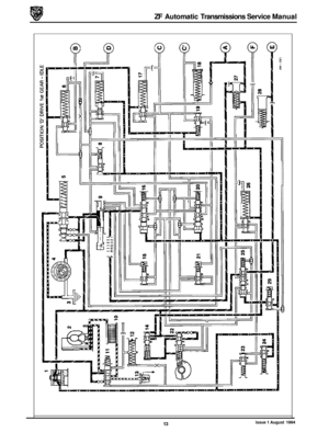
1.1.6 Gearshift Selection
Gearshift selection is by movement of the shift lever which through a selector cable causes repositioning ofthe manual
(selector) valve to direct oil pressure to the required shift valve. The automatic shift points are determined by acceler- ator position and road speed: throttle movement moves a cam on the throttle valve, directing oil pressure to the shift
valves and modulator valve, road speed modulates hydraulic pressure through a centrifugal governor driven by the
transmission output shaft. Operation
of the hydraulic control system is shown diagrammatically in the circuit dia
-
grams on the following pages.
I I
I
I
2 -3- I
I I
I
I
- I
I I 1 4 -5 - - -
+ ! + I I 'I 10 I I
I
I 1
1, 1-Y I
I I
I
I
1. Engine 8. Pump regulator valve 2. Torque converter 9. Damper
3. Pump 10. Governor valve 4. Clutch & gears 11. Shift valve 5. Governor 12. Kickdown cable &throttle cam 6. Shift 13. Throttle / modulator valves 7. Solenoid valve 14. Transmission housing
Fig.
1 Schematic Diagram of Hydraulic Control
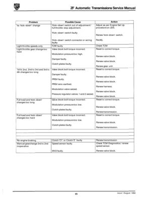
I. 1.7 Throttle Valve Mechanism (kick-down)
The throttlevalve or 'kick-down' mechanism comprises a cable connected between throttle body pedal and the throttle
valve cam/ quadrant located on the selector valve shaft; the cam operates the throttle valve housed within the throttle
valve block. The travel of the valve is proportional to throttle positions and alters shift speeds and pressures during
gearshifts to take account of throttle position. The mechanism also provides for immediate selection of a lower
ratio (eg when overtaking) by depressing the accelerator beyond the normal full
-throttle position. 'Kick-down' is oper- ated by movement of the throttle cable into the 'kick-down' position causing full movement of the throttle valve and
directing oil flow to the shift valves.
1.1.8 Starter Inhibit Switch
The starter inhibit switch prevents the starter motor from being operated when the shift lever is not in position 'P' - Park or position 'N'- Neutral. The switch is located in the gear selector housing.
I. I. 9 Gearshift Interlock
A brake pedal /shift lever interlock is incorporated in the gearselector mechanism. Theshift lever may only be moved
from the 'P'- Park position if the ignition key switch is in position '11', and the foot brake pedal is applied. The ignition
key cannot be removed from the ignition switch unless the shift lever is in the 'P' -Park position. Once the ignition key
has been removed, the shift lever is locked in the park position.
The gearshift interlock is operated by an electrical solenoid located adjacent to the selector; an override latch is incorpo
- rated into the mechanism to enable the gearshift interlock to be manually overridden in the event of electrical failure
or when towing.
8 Issue 1 August 1994
Page 11 of 74
ZF Automatic Transmissions Service Manual
2
A. C1 Clutch valve B. 2-3 shift valve piston
C. C clutch damper valve
D. B clutch damper E. 1-2 shift valve piston F. D clutch valve and piston G. Pressure regulating valve
H. Manual (selector) valve I. A clutch damper J. 1-2 shift valve K. B clutch damper valve L. C clutch damper
M. 2-3 shift valve N. Converter pressure valve
M: Numerical annotations are not used in this application.
Fig.
1 Manual Valve Block
1
I
JLL-699
Issue 1 August 1994 5
Page 12 of 74
ZF Automatic Transmissions Service Manual
1
JL4-70
A. One way valve (lubrication) B. 2nd gear inhibit valve C. F clutch damper D. F clutch inhibit valve (reverse)
E. 3-4 shift valve piston
F. 3-4 shift valve G. 1st gear inhibitvalve H. F clutch valve I. E clutch damper
J. C1 clutch damper
Note: Numerical annotations are not used in this application.
Fig.
1 Rear Valve Block
6 Issue 1 August 1994
Page 13 of 74
ZF Automatic Transmissions Service Manual
I1
B
12
A. Modulator valve
B. Throttle valve / Kick-down valve C. Reverse inhibit valve
Note: Numerical annotations are not used in this application. JU-701
Fig. 1 Throttle Valve Block
Issue 1 August 1994 7
Page 14 of 74

1. Governor 16. 1 - 2
Shift Valve
2. Torque Converter 17.")
ZF Automatic Transmissions Service Manual
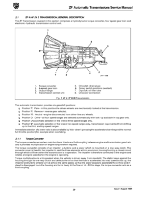
1.2 HYDRAULIC CIRCUIT DIAGRAMS
Key To Hydraulic Circuit Diagrams (commencing on page IO)
1. Governor 16. 1 - 2
Shift Valve
2. Torque Converter 17.
Clutch
'C' Valve
3. Sump
18. Clutch 'C" Damper
4. Pump 19.
Clutch
'C" Valve
5. Pressure Regulating Valve 20.
2
- 3 Shift Valve
6. Clutch
'B' Valve And Damper 21.
2nd Gear Inhibit
7. Clutch 'D' Valve And Damper 22.
Throttle Valve
8. Reverse Gear Inhibit 23. Converter Clutch Lock-up Control Valve
9. Manual Valve 24.
Converter Clutch Hysteresis Valve
IO. Oil Cooler 25. 3 - 4 Shift
Valve
11. Converter And Reversing Valve 26.
Clutch 'F' Valve And Damper
12. Converter Clutch Damper 27.
Clutch
'A' Damper
13. One
-way Valve
14. Modulator Valve
15. 1st Gear Inhibit
A Clutch'A'
B Clutch'B'
C Clutch'C'
C1 Clutch 'C"
D Clutch'D'
E Clutch'E'
F Clutch'F'
Exhaust
Throttle
Orifice Branch
Main Pressure
Converter Pressure
Throttle Pressure
28. Clutch 'E' Damper
29. Clutch 'F' Inhibit Valve (Reverse)
Vlll HII Governor Pressure
IX - Locking Pressure
X -1- Modulation Pressure
XI - Pump Pressure
XI1 Lubrication Pressure
issue 1 August 1994 9
Page 15 of 74
ZF Automatic Transmissions Service Manual
r------R-----J I, I, II II II
10 Issue 1 August 1994
Page 16 of 74
ZF Automatic Transmissions Service Manual
w cn
w a
a
2
a
0 t
z
cn
2
I III
Issue 1 August 1994 11


 B. 2nd gear inhibit valve C. F clutch damper D. F clutch inhibit valve (reverse)
E. 3-4 shift valve piston
F")


