Page 41 of 74

Action
No changes at light throttle
setting
Change points incorrect at full
throttle")
ZF Automatic Transmissions Service Manual
Problem Possible Cause
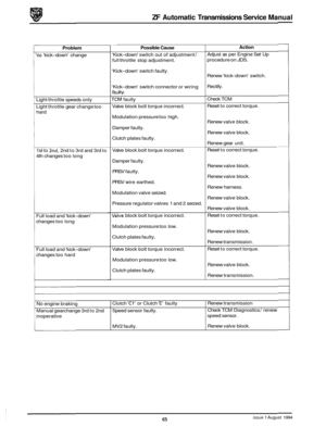
1.3.6 Fault Finding Chart (continued)
Action
No changes at light throttle
setting
Change points incorrect at full
throttle setting
No changes at 'kick-down' - 1st
to 2nd 12nd to 1st
No changes at 'kick-down' - 2nd
to 3rd
13rd to 2nd Dirty
governor.
Shift valves sticking.
'Kick
-down' cable setting incorrect
'Kick
-down' cable setting incorrect
'Kick
-down' cable setting incorrect Renew
governor.
Service
1 renew valve block.
Adjust setting
Adjust setting
Adjust setting
Service
1 renew valve block.
Service
1 renew valve block.
Poor changes
Harsh changes at low throttle Throttle
valve ('kickdown') cable
, setting incorrect
I Defective damper.
Modulation pressure too high.
'Kick
-down' cable setting incorrect. I
j Clutch plates damaged.
!
Soft changes at full throttle and
'kick
-down' Defective damper.
'Kick-down' cable setting incorrect.
I
Adjust setting
Service
/ renew valve block.
Service
1 renew valve block.
Adjust setting
,
Service / renew transmission.
Service
/ renew valve block.
Adjust setting.
Adjust setting.
Harsh changes
at full throttle and
'kick
-down' Modulation
pressure too low.
Clutch plates damaged.
Incorrect modulation pressure.
'Kick
-down' cable setting incorrect.
Defective damper.
Manual change 3rd to 2nd faulty
No engine braking
36 Issue 1 August 1994
Locking valve '2' sticking. Service 1 renew valve
block I governor.
Service
/ renew valve block / governor.
Service
1 renew transmission
Governor faulty.
Brake 'C' or 'E' damaged
Page 42 of 74

Action
>hange points at incorrect
;peeds
3eneral
Kick-down cable sticking
Voisy and")
ZF Automatic Transmissions Service Manual
Problem Possible Cause
1.3.6 Fault Finding Chart (continued)
Action
>hange points at incorrect
;peeds
3eneral
Kick-down' cable sticking
Voisy and no drive after a long
ourney
dery noisy and no drive
3il leaks
3il dripping from the bell
iousing
-eakage between transmission
and oil sump
-eakage between intermediate
date and main housing
:especially at pump pressure
Doint)
3il leak at output
-eakage from cooler pipes
-eakage between main housing
jnd tail housing
3il leak from 'kick-down' cable at
:ransmission end 'Lock
-up'
safety valve sticking.
'Kick
-down' cable setting incorrect.
No 4th gear.
Governor pressure incorrect.
Nipple in throttle cam is worn.
Too much friction in sleeve of
'kick
-down' cable.
Throttle pressure piston sticking.
Oil filter on valve block faulty
Drive plate is worn or broken
Seal ring in pump housing
damaged.
Defective pump 0
-ring.
Pump housing porous.
Converter leaking from welded
seam.
Bolts incorrectly
torqued.
Sump gasket damaged.
Bell housing bolts loose.
Gasket damaged.
Output oil seal damaged
Loose connections.
Pipes damaged.
Cooler leaks.
Loose bolts.
Gasket damaged.
'0' ring connection damaged Service
/ renew valve
block / governor.
Adjust setting.
Check cable adjustment, service
/
renew valve block / governor.
Service
1 renew valve block I governor.
Replace cable.
Replace cable
Service
/ renew valve block.
If there is no burnt lining in the sump,
renew the filter and oil. If debris is
present, renew the transmission.
Renew the drive plate
Renew seal.
Renew
@ring.
Renew pump housing.
Renew converter.
Tighten bolts to specified torque.
Renew sump gasket.
Tighten bolts to specified torque.
Renew gasket.
Renew seal
Tighten connections.
Renew pipes.
Renew cooler.
Tighten bolts.
Renew gasket.
Renew
'0' ring or complete cable
issue 1 August 1994 37
Page 43 of 74

Problem
.oss of oil through breather
3il leak at intermediate plate
-eakage between gearbox and
2xtension housing
Uoises
iigh pitched squeaking noise,")
1.3.6 Fault Finding Chart (continued)
Problem
.oss of oil through breather
3il leak at intermediate plate
-eakage between gearbox and
2xtension housing
Uoises
iigh pitched squeaking noise,
jependant on engine RPM, in all
jears, when oil is warm and
accompanied by intermittent
hive after a long journey
iigh pitched noise in all
Dositions, especially if oil is cold.
Sucking noise from pump.
dery noisy in 'lock-up'
rorsional vibrations from engine
Nhen in 'lock-up'
-oud noisewhen converter
:lutch engages
Engine vibrations when
:onverter clutch engaged
Possible Cause
Oil level too high.
Incorrect oil.
Breather blocked.
No breather cap.
'0' ring breather damaged.
Securing clip faulty.
Blanking plug loose
Fastening screws loose.
Gasket faulty.
Dirty filter
Low oil level.
Filter not sealing.
Leaking valve block.
Filter damaged.
Torsion damper faulty
Engine
RPM is too low, 'lock-up'
shift point incorrect
Torsion damper defective
Change point too low
Action ___ Check level.
Remove transmission, ensuring that
it
is drained (including torque converter,
oil cooler and pipes).
Change breather, check for foul
condition
of foam insulation pad.
Fit cap or renew breather.
Remove tail housing and replace
'0'
ring.
Renew clip.
Tighten plugs. Renew sealing washers.
Tighten screws to specified torque.
Renew gasket.
If there is no debris in the sump, renew
the filter and oil.
If debris is present,
renew the transmission.
Top-up as necessary.
Check
I renew 0-ring.
Service
/ renew valve block.
Check filter.
Renew torque converter
Service
I renew valve block
Renew converter
Check valve block ~~
Issue 1 August 1994 38
Page 44 of 74

ZF Automatic Transmissions Service Manual
2.1
electronic-hydraulic transmission control unit.
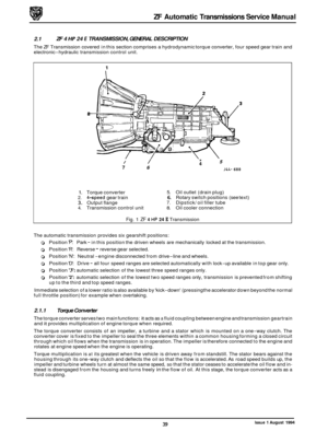
ZF 4 HP 24 E TRANSMISSION, GENERAL DESCRIPTION
The ZF Transmission covered in this section comprises a hydrodynamic torque converter, four speed gear train and
1
/ /
7 6
, 5 4
J4L- 688
1. Torque converter 5. Oil outlet (drain plug)
2. 4-speed gear train 6. Rotary switch positions (see text)
3. Output flange 7. Dipstick/ oil filler tube 4. Transmission control unit 8. Oil cooler connection
Fig. 1 ZF 4 HP 24 E Transmission
The automatic transmission provides six gearshift positions:
0 Position 'P': Park - in this position the driven wheels are mechanically locked at the transmission.
0 Position 'R': Reverse - reverse gear selected.
0 Position 'N': Neutral -engine disconnected from drive-line and wheels.
0 Position 'D': Drive - all four speed ranges are selected automatically with lock-up available in top gear only.
0 Position '3': automatic selection of the lowest three speed ranges only.
0 Position '2': automatic selection of the lowest two speed ranges only, transmission is prevented from shifting
up to the third and top speed ranges.
Immediate selection of a lower ratio is also available by 'kick
-down' (pressing the accelerator down beyond the normal
full throttle position) for example when overtaking.
2.1.1 Torque Converter
The torque converter serves two main functions: it acts as a fluid coupling between engine and transmission geartrain
and it provides multiplication of engine torque when required.
The torque converter consists of an impeller, a turbine and a stator which is mounted on a one
-way clutch. The
converter cover is fixed to the impeller to seal the three elements within a common housing forming a closed circuit
through which oil flows when the transmission is in operation. The impeller is therefore connected to the engine and
rotates at engine speed when the engine is operating.
Torque multiplication is
at its greatest when the vehicle is driven away from standstill. The stator bears against the
housing through its one-way clutch and deflects the oil so that the flow is accelerated. As road speed builds up, the
impeller and turbine wheels turn at almost the same speed, so that the stator ceases to accelerate the oil flow and in- stead is disengaged from the housing and turns freely in the flow of oil. At this stage, the torque converter acts as a
fluid coupling.
Issue 1 August 1994 39
Page 45 of 74

ZF Automatic Transmissions Service Manual
The torque converter acts in all four forward gears and in reverse. The converter lock-up clutch closes in 4th gear at
a point depending on road speed and accelerator position; engine power is then transmitted
by purely mechanical
means.
A low
-loss oil pump in the front of the transmission housing supplies the converter, the automatic gear shift and the
lubrication circuit; oil is drawn from a sump in the bottom of the gear train housing through a filter. The pump drive
gear is keyed to the converter impeller hub and therefore turns when the engine is running, thereby pressurizing the
oil.
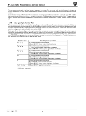
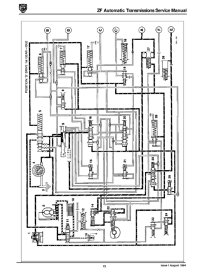
2.1.2 Four-speed Epicyclic Gear Train
The torque converter drives a mechanical epicyclic gear train providing four forward ratios and reverse. Individual ra-
tios are obtained by coupling together the various parts of the gear train by means of solenoid-operated, hydraulically
actuated multi-disc clutches and brakes; built in freewheels permit gear shifts without any interruption of the power
flow.
For information on the operation of the solenoids, clutches, brakes and freewheels, refer to the table below and the
schematic diagrams shown overleaf.
A parking lock pawl is provided at the rear of the gear train, operating on a toothed wheel attached to the output shaft;
the parking lock is operated from the selector (position
'P) by actuator rod.
An electro
-magnetic sensor detects output shaft revolutions by means of a toothed disc attached to the shaft; one rev- olution of the shaft is equal to 36 pulses. The electrical signal from the sensor is passed, via a screened cable, to the
TCM.
R
Park,
Neutral
Solenoid ~
MV2
MVI, MV2
MVI, MV3
MV2
-
MV2
OWC
= one way clutch
Resulting clutch operation
A Clutch drives annulus clockwise
D Clutch OWC holds F carrier against shaft clockwise
E Clutch & OWC drives output shaft clockwise
A Clutch drives annulus clockwise
C1 Clutch holds sungear against anti-clockwise
C Clutch
& OWC holds sungear against anti-clockwise
A Clutch drives annulus clockwise
B Clutch drives sungear clockwise
C Clutch
& OWC holds sungear against anti-clockwise
A Clutch drives annulus clockwise
B Clutch drives sungear clockwise
C Clutch
& OWC holds sungear against anti-clockwise
B Clutch drives sungear clockwise
D Clutch holds carrier against clockwise
E Clutch & OWC drives output shaft anti-clockwise
E Clutch & OWC applied (hydraulics)
40
Issue 1 August 1994
Page 46 of 74

ZF Automatic Transmissions Service Manual
2.1.3 Operation Of Gear Train Clutches
Operation of the gear train clutches to provide the five gear ratios is as follows:
1st Gear
Clutches 'A' and 'E' are engaged.
The front planet gear carrier of gear set
'9' is locked against
the housing of through freewheel '10' when the engine is
pulling, but is over
-run when the engine is coasting.
Epicyclic gear set
'10' rotates as a solid block with the second
planet set.
2nd Gear
Freewheel '15' over-runs.
Clutches
'Cl' and 'C' lock the sun gear to the housing.
* Clutches 'A','Cl','C' and 'E' are engaged.
3rd Gear
Clutches 'A','B','C' and 'E' are engaged.
Freewheels '14' and '15' are over
-run.
Epicyclicgearsets'9'and'lO'rotateasa solid blockat a ratio
of 1:l.
4th Gear
Clutches 'A','B','C' and 'F' are engaged.
Freewheels
'14','15' and '16' are over-run.
Epicyclic gear set
'9' rotates as a solid block.
The hollow shaft with the sun wheel of epicyclic gear set '10'
is
locked.
Above a predetermined road speed, lock-up clutch '2' locks
torque converter '3' solid to prevent slip.
I
J4L-G 9 1 Fig. 1
JLL-69: Fig. 2
J 4L-69E Fig. 3
5' 4' 3
JLL-697 Fig. 4
41 Issue 1 August 1994
Page 47 of 74

ZF Automatic Transmissions Service Manual
Reverse Gear
Clutches 'B','D' and 'E' are engaged.
As the front planet gear carrier of epicyclic gear SE '9' is
locked, the direction of output shafgt rotation is reversed.
Epicyclic gear set '10' also rotates as a solid block. I
~~~-698
Fig. 1
2.1.4 Transmission Control Unit
The electronichydrauliccontrol unit comprising a series of valve blocks housing a cable-operated manual valve, con- trol pistons and pressure valves is attached to the underside of the transmission housing; the unit controls the oper- ation of the gear train clutches and directs oil pressure to the appropriate system components (refer to illustrations,
pages 43 to 46) to operate the transmission.
The four valve blocks in which the control valves, pistons etc are located, are mounted and connected through a main
gallery plate. The three solenoid valves
MVI, MV2 and MV3 and the pressure regulator operating solenoid are located
on the upper surface of the plate; electrical connections between the solenoids and the transmission and transmission
control unit are via cable harnesses (refer to relevant diagrams and tables for details of the various pin connections).
Operation of the transmission control unit is through an electronic Transmission Control Module
(TCM) which on re-
ceipt of electrical signalsfrom transmission and engine management sources, activates the hydraulic pressure regulat- ing and shift valves via solenoid valves located on the valve block. The gearshift selector transmits movement, via the
selector cable, to the selector lever on the side of the gearbox; this rotates the selector shaft which controls the manual
selector valve. The rotary position of the shaft is monitored by the rotary switch.
42 Issue 1 August 1994
Page 48 of 74

ZF Automatic Transmissions Service Manual
2.1.6 Transmission Rotary Switch
This switch is located on a square extension of the transmission selector shaft and is linked to the shift lever via the
selector cable. The switch comprises a selector bar which moves across a series of copper segments located on the
switch quadrant. The copper segments are set out in seven bands, each band providing an electrical output or com
- bination of outputs to the TCM.
The electrical outputs to the TCM are in the form of a three
-digit code which takes up three of the seven bands of the
quadrant; the remaining four bands are used for reverse, ground and start inhibit.
2.1.7 Decoder Module
The decoder module, located on the right hand side of the J-gate assembly, is used to translate the three-digit codes
from the rotary transmission switch into single-line functions to feed the illumination module and to provide the fol-
lowing information:
. Cruise control, ie when cruise control can or cannot be engaged.
. Indication when the vehicle is not in 'P' Park.
. Provide the ECM with a Park/ Neutral signal.
2.1.8 Performance Mode Switch
This switch, located on the shift lever surround, provides two alternative shift patterns:
. 'Normal Mode' -for everyday use,
. 'Sport Mode'- gear changes take place at higher road speeds in order to enhance performance.
Note: Torque converter 'lock-up' occurs in fourth gear in each mode.
2. I. 9 'Kick-down' Mechanism
'Kick-down' is activated by the final travel of the accelerator pedal which contacts a floor-mounted switch located be- hind the pedal. Operation of the switch provides a signal to the TCM that a downward change is required. The switch
is adjustable to ensure that the pedal does not overtravel and stretch the cable.
2.1.10 Reverse Safefy Inhibit
If 'R' Reverse is selected when the vehicle is travelling forwards at more than 5 mile / h, solenoid valve MV2 will be
energised to prevent engagement of reverse gear.
2.1.11 Gearshift hterlock
A brake pedal /gearshift interlock is incorporated in the gear selector mechanism. The gear selector lever may only
be moved from the P - Park position if the ignition key switch is in position II and the foot brake is applied.
The ignition key cannot be removed from the ignition switch unless the shift lever is in
the 'P - Park position. Once
the ignition key has been removed, the shift lever is locked in the park position.
2.1.12 Starter Inhibit Switch
The starter inhibit switch prevents the starter motor from being operated when the shift lever is not in position 'P' - Park or position 'N' - Neutral. The switch is located in the gear selector housing.
issue 1 August 1994 47