1994 HONDA INTEGRA Wheel
[x] Cancel search: WheelPage 672 of 1413
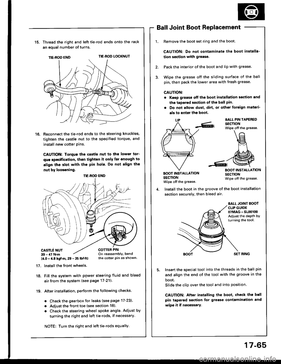
15.Thread the right and lefi tie-rod ends onto the rack
an eoual number of turns.
TIE-ROO ENDTIE.ROD LOCKNUT
R€connect the tie-rod ends to the steering knuckles,
tighten the castle nut to the specified torque, and
install new cotter pins.
CAUTION: Iorquo tho castle nut to tho lower tor-
que lpocification, thsn tighton it only far cnough to
align thc slot with tho pin hole. Do not align tho
nut by loosoning.
CASILE NUT39 - 47 N.m14.0 - a.8 kgf.m. 29 - 35 lbf ftl
17. lnstallthe front wheels.
18. Fill the system with pgwer steering fluid and bleed
air from the system (see page 17-21).
19. After installation. perform the following checks.
. Check the gearbox Jor leaks (see page 17-231
. Adjust the front toe (see section 18).
o Check the steering wheel spoke angle. Adjust by
turning the right and left tie-rods, if necessary.
Ball Joint Boot Replacement
Remove the boot set ring and the boot.
CAUTION: Do not contaminate ihe boot in3talls-
tion section with gr€aso.
Pack the interior of the boot and lip with grease.
Wipe the grease off the sliding surface of the ball
pin, then pack the lower area with fresh grease.
CAUTION:
. Ke€p g;eass off the boot in3tallation section and
tho laperad section of the ball pin.
. Do not altow dust, di.t, or other toreign mat6ti-
als to enter tho boot,
LIPBALL PIN TAPEREDSECTIONWipe off the grease.
BOOT INSTALLATIONSECTIONwiDe off the grease.
BOOT INSTALLATIONSECTIONWipe off the grease.
COTTER PINOn reassembly, bendthe cotter pin as shown.
Install the boot in the groove ot the boot installation
section securely, then bleed air.
SALL JOINT BOOTCLIP GUIDE07MAG - SL(x)l00Adiust the depth byturning the tool.
SET RING
Insert the special tool into the threads in the ball pin
and align the end of the tool with the groove in the
boot.
Slide the clip over the tool and into position
CAUTION: After installing the boot, check th. b.ll
pin taperod section tor grease contamiration and
wipe it if nocossary.
NE.ROD END
Turn the right and left tie-rods equally.
17-65
Page 1028 of 1413
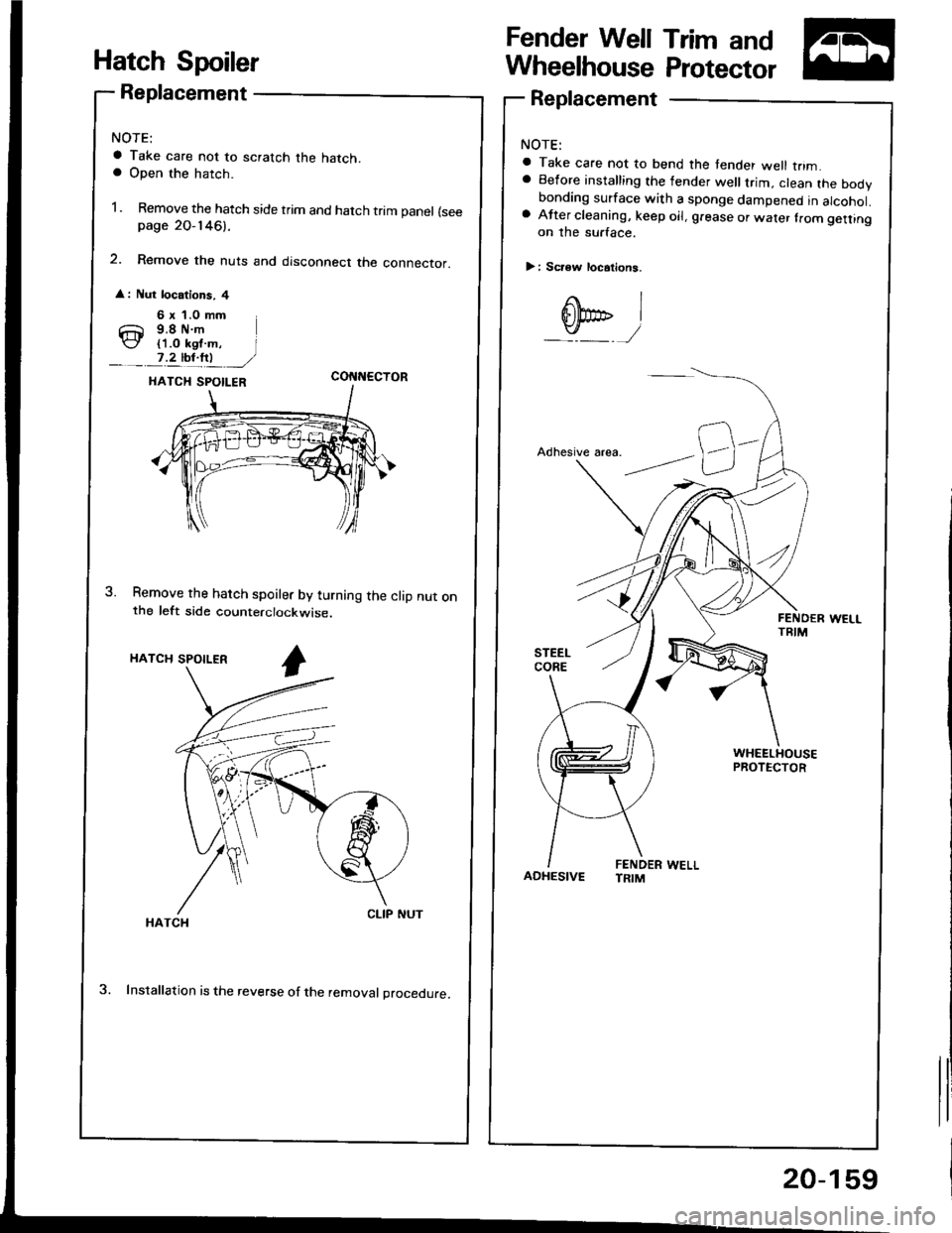
Hatch Spoiler
Replacement
a Take care not to scratch the hatch.a Open the hatch.
1. Remove the hatch side trim and hatch trim panel (seepage 2O-146).
2. Remove the nuts and disconnect the connector.
: Nut locations, 4
6 x 1.0 mm
Ch 9.8 N.m(J (1.0 ksl m, I__. 7,4b1!t ,/coI{t{EcroR
Remove the hatch spoiler by turning the clip nut onthe left side counterclockwise.
HATCH SPOILER
3. Installation is the reverse of the removal procedure.
Fender Well Trim and
Wheelhouse Protector
Replacement
a Take care not to bend the tender well trim.a Before installing the lender well trim, clean the bodvbonding surface with a sponge dampened in alcohol.a After cleaning, keep oil, g.ease or wafer lrom getlingon the surface.
> i Scr€w locations.
I
ADHESIVEFENDER WELLTRIM
20-159
Page 1037 of 1413
Heater and Air Conditioning
Heater ........ 21-1
Air Conditioning .......... ..22-1
SUPPLEMENTAL RESTRAINT SYSTEM {SRS}
The Integra SRS includes a driver's airbag, located in the steering wheel hub. In addition. all models except the
RS model for Canada have a front passenge.'s airbag located in the dashboard above the glovs box. Information
necessary to safely service the SRS is included in this Service Manual. ltems msrk€d with an asterisk (') on the
conlents page include, or are located near, SRS components. Servicing, disassembling or,eplacing thes€ items
will require special precautions and tools, and should therefore be done by an authorized Acura dealer.
a To avoid r6nd6dng tho SRS inoporativo. which could lead to personal injury or dealh in tho svont ot a sevele
frontal collision, all SRS servica work musl b€ portormed by an authorized Acura dealer.
a lmpropor sorvico procaduro3, including incorrect romoval and installatlon of tho SRS, could load to porsonal iniu-
ry causod by uninlonlional activation of tho ailbag8.
a All SRS eloctdcal widng harnossos are covored with yollow in3ulation. Relatsd compononts a.o locatod in tha
stsering column, flont console, daehboard, and dashboafd low6r pan6l, and in lhe dsshboa.d above lh€ glove
box. Do not uao electdcal tost equipmont on theae circuhs.
NOTE: The original radio has a coded theft protection circuit. Be sure to get the customer's code number beto.e
- disconnecting the battery.- removing the No. 32 (7.5 A) luse from the under-hood fuse/relay box.- removing the radio.
After service, reconnect power to the radio and turn it on. When the word "CODE" is displayed, enter the cus-
tomer's 5-digit code to restore radio operation.
Page 1126 of 1413
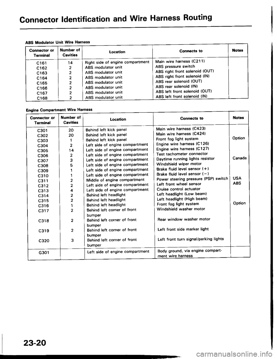
Connector ldentification and Wire Harness Routing
ABS Modulatol Unit Wile Harness
Engine Compartmont Wile Hatnaaa
Connoctor or
Torminal
Numbor ot
CaviiieELocationConnocta tooies
Ltol
c162
c163
c164
c165
c166
c't 67
c168
't4
2
2
Right side of engine comPartment
ABS modulator unit
ABS modulator unit
ABS modulator unit
ABS modulator unit
ABS modulator unit
ABS modulator unit
ABS modulator unat
Main wire harness (c21 1)
ABS Dressure switch
ABS right Jront solenoid (OUT)
ABS right front solenoid (lN)
ABS rear solenoid (OUT)
ABS rear solenoid llN)
ABS le{t front solenoid {OUT)
ABS left tront solenoid (lNl
Connector or
Tolminal
Numbd of
CaviliesLocationConnocta tot{oioE
c301
c302
c303
c304
c305
c306
c307
c308
c309
c310
c31 1
c312
c313
c314
c315
c316
c317
c318
c319
c320
20
20
1
2
14
2
1
1
2
4
2
2
1
2
2
5
Behind left kick Panel
Behind left kick panel
Behind lett kick Panel
Left side of engine compartment
Left side of engine comPartment
Left side of engine comPartment
Left side o{ engine comPartment
Left side of engine comPartment
Left side of engine compartment
Lelt side oJ engine comPartment
Middle of engine comPartment
Left side of engine comPartment
Left side oJ engine comPafiment
Behind leJt headlight
Behind left headlight
Behind left headlight
Behind left corner ot front
bumper
Behind lett corner ot front
DUmper
Behind left corner of ftont
DUmper
Behind left cornet of front
DUmper
Main wire harness (C4231
Main wire harness (C424)
Front fog light sYstem
Engine wire harness (C126)
Engine wire harness (C 127)
Test tachometer connector
Daytime running lights resistor
Windshi€ld wiper motot
Brake fluid level sensor ( + |
Brake fluid level sensor (- )
Power steering pressure (PSPI
Lett front wheel sensor
Cruise control actuator
Left headlight (Low beam)
LeJ-t headlight (High beam)
Front fog light system
Windshield washer motor
switch
Rear window washer motor
Left front side matker light
Left front tu.n signal/parking lights
USA
ABS
Option
Canada
Option
G301Lett side of engine comPartmentBody ground, via engine comPart-
ment wire harness
23-20
Page 1128 of 1413
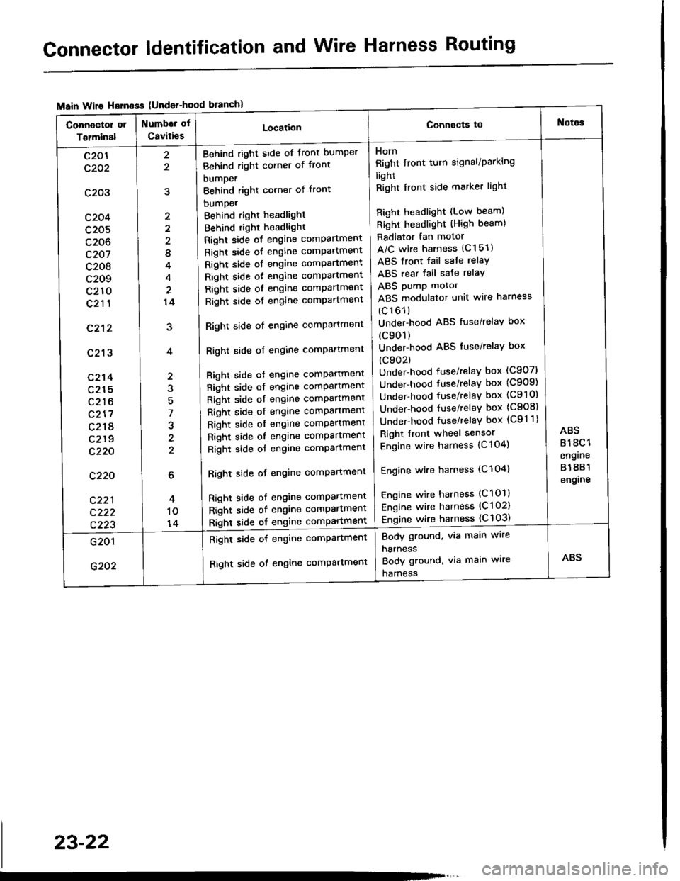
Connector ldentification and Wire Harness Routing
{Undor-hood
Horn
Right tront turn signal/Parking
light
Right Iront side marker light
Right headlight (Low beam)
Right headlight (High beam)
Radiator fan motor
A/C wire harness (C151)
ABS front fail saJe relay
ABS rear fail sate relay
ABS pump motor
ABS modulator unit wire harness
(c161)
Under-hood ABS fuse/relaY box
(c901)
Under-hood ABS fuse/relaY box
(c902)
Under-hood fuse/relay box (C907)
Under-hood tuse/relaY box (C909)
Under-hood fuse/relay box (C9l Ol
Under-hood fuse/relaY box (C908)
Under-hood fuse/relaY box (C91 1)
Right front wheel sensor
Engine wire harness {C 104)
Engine wire harness (C'l 04)
Engine wire harness (C101)
Engine wire harness (C l 02)
Engine wire harness {C 103)
Behind right side of tront bumper
Behind right corner of tront
bumper
Behind right corner of front
bumpet
Behind right headlight
Behind right headlight
Right side of engine comPartment
Right side of engine comPartment
Right side ot engine comPartment
Right side oJ engine comPartment
Right side of engine comPartment
Right side oJ engine comPartment
Right side of engine comPartment
Right side of engine comPartment
Bight side ot engine comPattment
Right side of engine comPartment
Right side of engine comPartment
Right side of engine comPartment
Right side of engine comPartment
Right side of engine comPartment
Right side of engine comPartment
Righl side ot engine comPartmenl
Right side of engine compartmenl
Right side of engine comPartmen'
Right side of engine comPartment
8
4
14
7
J
2
c201
c202
c203
c204
c205
c206
c207
c208
c209
c210
c211
c212
c213
c214
c215
c216
c217
c218
c219
c220
c220
c221
c222
c223
Body ground, via main wire
harness
Body ground, via main wire
harness
Right side of engine compartment
Right side of engine comPartment
23-22
Page 1148 of 1413
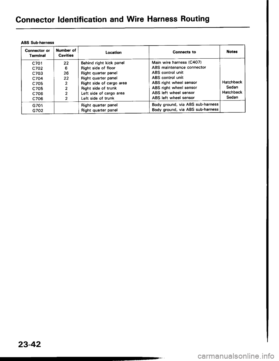
Gonnector ldentification and Wire Harness Routing
ABS Sub-harn6ss
Connactor ol
Terminal
Number of
CavitiesLocationConn€cts toNotas
c701
c702
c703
c704
c705
c705
c706
c706
22
20
22
2
2
Behind right kick panel
Right side of Jloor
Right quarter panel
Bighl quarter panel
Right side of cargo area
Right side of trunk
LeJt side of cargo area
Left side ot trunk
Main wire harness (C407)
ABS maintenance connecto.
ABS control unit
ABS control unit
ABS right wheel sensor
ABS right wheel sensor
ABS left wheel sensor
ABS left wheel sensor
Hatchback
Sedan
Hatchback
Sedan
G701
G702
Right quarter panel
Right quarter panel
Body ground, via ABS sub-harness
Body ground, via ABS sub-harness
23-42
Page 1178 of 1413
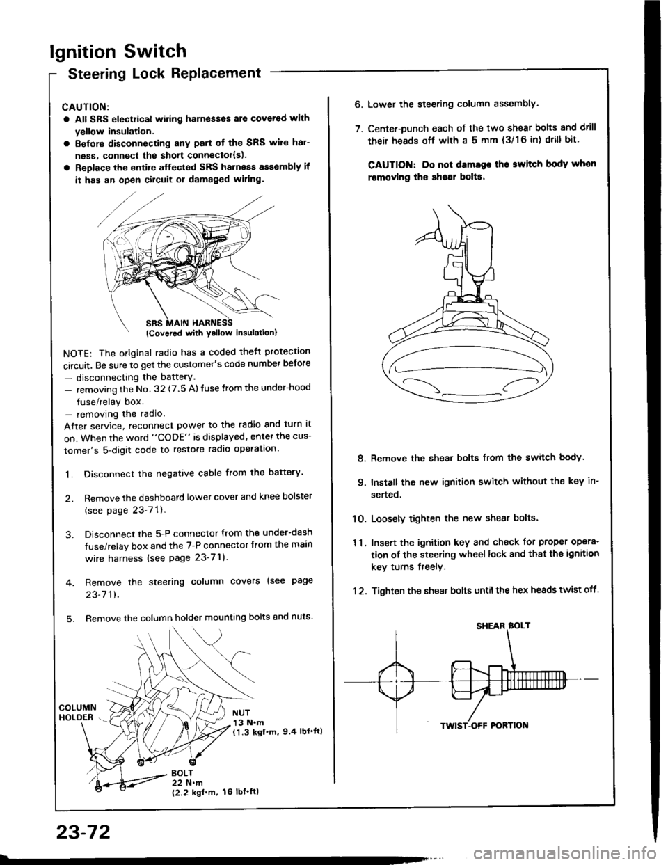
lgnition Switch
Steering Lock Replacement
CAUTION:
a All SRS electrical wiring harnesses ale covsred with
yellow insulation.
a Belore disconnecting any parl ot the SRS wir€ hal-
ness, connecl the short connector{s).
a Replace the entire alfected SRS harness a$6mbly il
it has an open circuit or damaged wiring.
NOTE: The original radio has a coded thett protection
circuit. Be sure to get the customer's code number betore
- disconnecting the batterY.
- removing the No. 32 (7.5 A) fuse from the under-hood
fuse/relay box.- removing the radio.
After service, reconnect power to the radio and turn it
on. When the word "CODE" is displayed, enter the cus-
tomer's 5-digit code to restore radio operation.
1. Disconnect the negative cable from the battery.
2. Remove the dashboald lower cover and knee bolster
(see page 23-7'l ).
3. Disconnect the 5-P connector from the under-dash
fuse/relay box and the 7-P connector trom the main
wire harness {see page 23-71).
4. Remove the steering column covers (see page
23-711.
5. Remove the column holder mounting bolts and nuts'
BOLT22 N.m
12.2 kgl'm.
NUT13 N.m(1.3 kgf.m, 9.4 lbl'ftl
23-72
16 tbt.ftl
6. Lower the steering column sssembly.
7. Center-Dunch each oJ the two shear bolts and drill
their heads off with a 5 mm {3/1 6 in) drill bit'
CAUTION: Do not dama96 tho switch body whon
r€movlng the shoar bol$.
Remove the shear bolts from the switch body.
Install the new ignition switch without the key in-
serted.
Loosely tighten the new shear bolts.
Insert the ignition key and check for proper opera-
tion of the steering wheel lock and that th€ ignition
key turns freely.
Tighten the shear bolts untilthe hex heads twist off.
8.
q
10.
11.
12.
Page 1183 of 1413
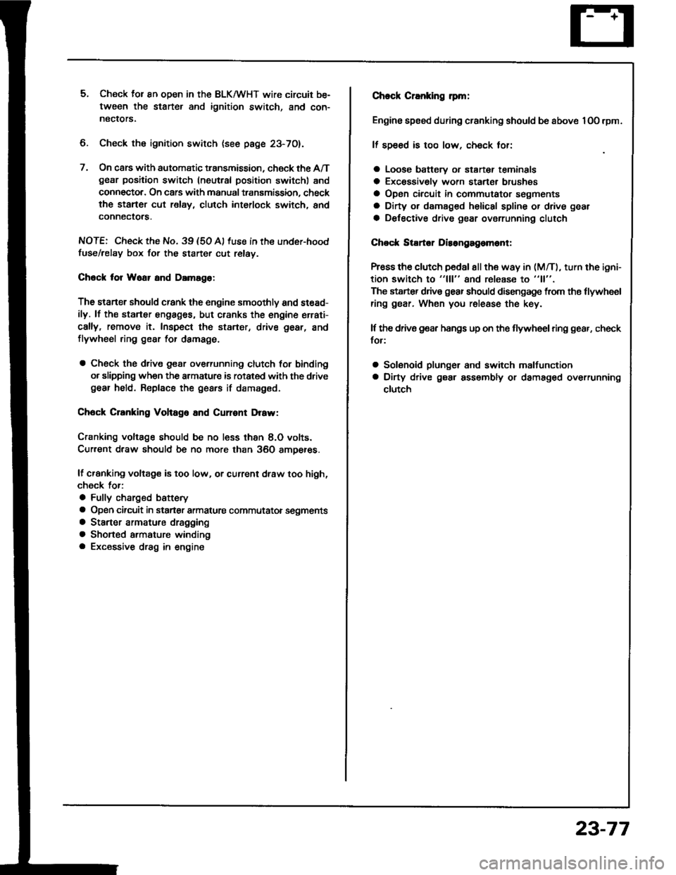
5. Check lor 8n op€n in the BLKMHT wire circuit be-
tween the staner and ignition switch, and con-
nectors.
6. Check the ignition switch (see page 23-70).
7, On cars with automatic transmission, check the A/Tgear position switch (neutral position switchl and
connector. On cars with manualtransmission, check
the staner cut relay, clutch interlock switch, and
connectors.
NOTE: Check the No. 39 (5O A) fuse in the under-hood
fuse/relay box for the starter cut relay.
Check tor Woar and Damago:
The starter should crank the engine smoothly and stead-
ily. lf th€ startsr engages, but cranks the engine errati-
cally, remove it. Inspect the starter, drive gear, and
flywheel ring gesr for damage.
a Check the drive gear overunning clutch for binding
or slipping when the armature is rotated with the drivegear held. Replace the gesrs if damaged.
Check Cranking Voltago 8nd Current Draw:
Cranking voltage should be no less than 8.O volts.
Current draw should be no more than 360 amperes.
lf cranking voltag€ is too low, or current draw too high,
check for:
a Fully charged battery
a Open circuit in starter armature commutatot segments
a Starter armature dragging
a Shoned armature winding
a Excessive drag in engine
Chack Cranking rpm:
Engine spsod during cranking should be above 1O0 rpm.
lf spe6d is too low, ch€ck for:
a Loose battsry or starter teminals
a Excessively worn starter brushes
a Open circuit in commutator segments
a Dirty or damaged helical spline or drive gear
a Defective drive gear overrunning clutch
Chock StErtor Disongagomoni:
Press the clutch pedal allth€ way in (M/T), turn the ioni-
tion switch to "lll" and rolease to "11".
The starter drive gear should disengage from the tlywheel
ring gear. When you rolease the key.
lf the drive gear hangs up on th€ flywheel ring gear, check
for:
a Solenoid plunger and switch malfunction
a Dirty drive gear assembly or damaged overrunning
clutch
23-77