Page 1190 of 1413
BRUSHES
Starting System
Starter Field Winding Test
1. Check for continuity between the brushes. lf there's
no continuity, replace the armature housing.
2. Check for continuity between each brush and the ar-
mature housing {ground) lf continuity exists, replace
the armatule housing.
Overrunning Clutch InsPection
Slide the overrunning clutch slong the shatt.
Does it move treely? ll not, replace it.
Rotate the overrunning clutch both ways.
Does it lock in one direction and rotate smoothly in
reverse? lf it does not lock in either direction or it
locks in both directions, replace it.
DRIVE G€AR
ll the starter drive gear is worn or damaged, replsce
the ovsrrunning clutch assembly; the gea. is not
available separately.
Check the condition of the flywheel or torque con-
verter ring gear if the starter drive gear teeth ale
damaged.
4.
23-8,4
CLUTCH GEAR
Page 1224 of 1413
Gauge Assembly
Removal
CAUTION:
a All SRS electrical wiling harnesses ara cover6d with
yollow insulation.
a Eofore disconnecting any part ol the SRS wiro har-
n6ss, connoct lhe short connector(sl.
a Roplace tho entirs affocted SRS harneas assembly if
it has an open circuit 01 damaged wi.ing.
SBS MAIN HARI{ESS(Covor6d with Yollow in.ulationl
Remove the two screws lrom the instrument panel.
Remove the instrument panel.
NOTE: Remove the instrument panel careJully
without damaging the cliPs.
1.
2.
lcarrio. tho SRs indicolor 8ignal)
CLIPS
23-118
Tilt the steering wheel down with the tilt adjustment
tevet.
Remove the three mounting screws, and spread a
protective cloth on the steering column.
PROTECTIVE CLOTH
Pry the gauge assembly out, and disconnect allcon-
nectors from it.
GAUGE ASSEMBLY
Take out the gauge assembly as shown.o.
Page 1227 of 1413
{From previous page)
Check tor continuity between theBLK terminal and body ground.ls there battery voltage?
Measure voltage between theORN and the BLK wire terminals.Ropair opon belw€onVSS and ground G101.
Ropair opon in tho BLKrYEL wirobotwoen VSS and undor-dsshluse/rolay box.
ls there about 5 V?
Ropair op6n in th6 ORN wire orshon to body ground.Raise the tront of the car and sup-port it with salety stands.
Touch a probe to the ORN wireand connect at to body groundthrough a voltmeter.
Putthe car in neutralwith kev ON.
Slowly rotate one wheel with theother wheel blocked.
Does voltage pulse from O toabout 1O V?Roplac. tho VSS {see page23-1221.
Touch a probe to the ORN wireand connect it to body groundthrough a voltmeter.
Slowly rotate one wheelwith theother wheel blocked.
Ropair opon in th6 OBil wire bo-tween tho VSS and th6 3p.odo-molgt.
Ooes the meter indicatepulsing voltage?
23-121
Page 1237 of 1413

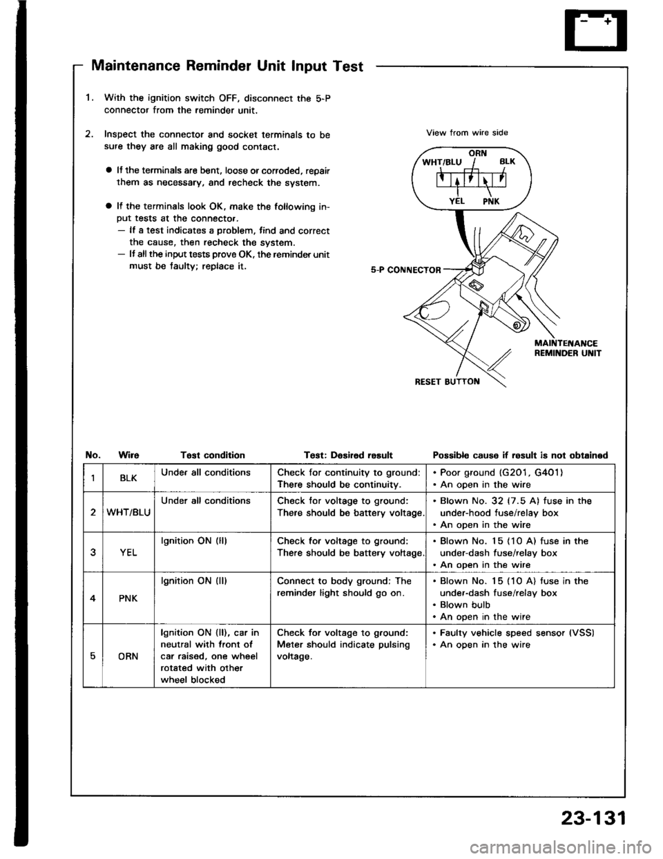
Maintenance Reminder Unit Input Test
1.With the ignition switch OFF, disconnect the 5-P
connector from the reminder unit,
Inspect the connector and socket terminals to be
sufe they are all making good contact.
a lJ the terminals are bent, loose orcorroded, repair
them as necessary, and recheck the svstem.
a It the terminals look OK, make the following in-
Put tests at the connecto..- lf a test indicates a problem, tind and correct
the cause, then recheck the system.- It allthe input tests prove OK, the reminder unit
must be taulty; replace it.
View trom wire side
No.WireTost condltionTest: DaEired rasultPossibl€ cause if result is not obtained
IBLKUnde. all conditionsCheck for continuity to ground:
There should be continuitv.
. Poor ground (G201, G4O1). An open in the wire
WHT/BLU
Under all conditionsCheck tor voltage to ground:
There should be battery voltage
. Blown No. 32 (7.5 A) fuse in the
under-hood tuse/relay box. An open in the wire
YEL
lgnition ON (lllCheck for voltage to ground:
There should be batte.y voltage
. Blown No. 15 (1O A) fuse in the
under-dash fuse/relay box. An open in the wire
4PNK
lgnition ON (ll)Connect to body ground; The
reminder light should go on.
Blown No. 15 (1O A) tuse in the
under-dash fuse/relay box
Blown bulb
An open in the wire
EORN
lgnition ON {ll), car in
neutral with lront ol
car raised, one wheel
rotated with other
wheel blocked
Check for voltage to g.ound:
Meter should indicate pulsing
voltage.
. Faulty vehicle speed sensor (VSS)
. An oDen in the wire
23-131
Page 1308 of 1413
Horn
SwitchTest(cont'd)
6.Remove the two TORX@ bolt6 using a TORX@ T30
bit, then remove the driver's airbag assembly.
Check for continuity between the horn positive ter-
minal and the steering column shaft with the horn
switch pressed, There should be no continuity.
HORN SwlTCHPOSITIVE TERMIITAL
TORXO BOLT(U!6 s TORxo T3O bitl
8.
a lf there is continuitv:- With cruise control: Test the set/resume
switch. lJ the switch is OK, replace the cable
reel.- Without cluise control: Replace the cable reel.
a lJ there is no continuity. remove the steering
wheel and the four screws, then remove the
steering wheel cover. Replace the faulty horn
switch.
Reinstall the steering wheel {see section 17).
DB|vEN'SAIRBAG ASSEMBLY
23-202
ilFrrI|qFrl"
Page 1353 of 1413

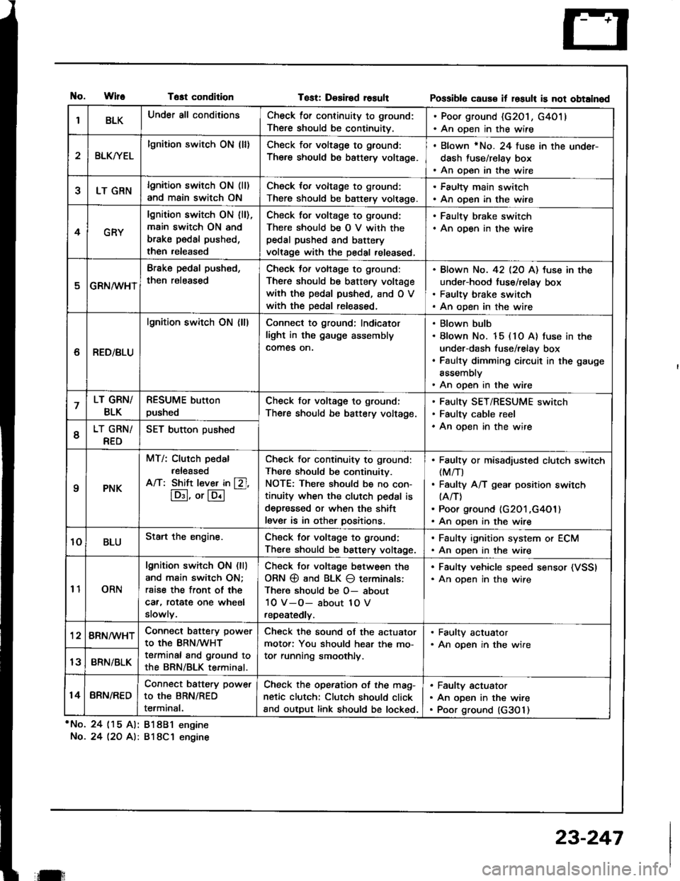
tlo.WlfeTost condition
*No. 24 (15 Al: 81881 engine
No.24 l2O A): 818C1 engine
Tost: Desired rosultPossibl6 caus€ it losult is not obtained
IBLKUnder all conditionsCheck for continuity to ground:
There should be continuitv.
. Poor ground (G201, G4011. An open in the wire
2BLKryEL
lgnition switch ON (ll)Check for voltage to ground:
There should be battery voltage.
. Blown rNo. 24 fuse in the under-
dash fuse/relay box. An open in the wire
5LT GRNlgnition switch ON (ll)
and main switch ON
Check for voltage to ground:
There should be battery volt€ge.
. Faulty main switch. An open in the wire
4GRY
lgnition switch ON lll),main switch ON and
brake pedal pushed,
then released
Check for voltage to g,ound;
There should be O V with thepedal pushed and battery
voltage with the pedal released,
. Faulty brake switch. An open in the wire
GRN/wHT
Brake pedal push€d,
then r€leased
Check tof voltage to ground:
There should be battery voltage
with the pedal pushed, and O V
with the Dedal released.
Blown No. 42 l2O Al tuse in the
under-hood fuse/relay box
Faulty brake switch
An open in the wire
6RED/BLU
lgnition switch ON (ll)Connect to ground; Indicator
light in the gauge assembly
comes on.
Blown bulb
Blown No. 15 (10 A) fuse in the
under-dash fuse/relay box
Faulty dimming circuit in the gauge
assembly
An open in the wire
7LT GRN/
BLK
RESUME button
pushedCheck for voltage to ground:
There should be battery voltage.
Faulty SET/RESUME switch
Faulty cable reel
An open in the wire6LT GRN/
RED
SET button pushed
qPNK
MT/: Clurch pedal
released
A/T: Shift l€ver in [Zl,
lD:I, or lE.l
-
Check for continuity to ground:
There should be continuity.
NOTE: There should be no con-
tinuity when the clutch pedal is
depressed or when the shift
lever is in other positions.
Faulty or misadiusted clutch switch(M/T)
Faulty A/T gear position switch(A/T)
Poor ground (G201 ,G4O1)An open in the wire
10BLUStart the engine.Chsck for voltage to ground:
There should be battery voltage.
. Faulty ignition system or ECM. An open in the wire
11ORN
lgnition switch ON (ll)
and main switch ON;
rsise the front of the
car, rotat€ one wheel
slowly.
Check Jor voltage between the
ORN @ and BLK O terminals:
There should be O- about
10 V-O- about 1O V
repeatedly.
. Faulty vehicle speed sensor (VSSI. An oDen in the wire
'128RN/WHTConnect battery power
to the BRN/WHT
terminal and ground to
the BRN/BLK terminal.
Check the sound of the actuator
motor: You should hear the mo-
tor running smoothly.
. Faulty actuator. An opsn in the wire
13BRN/BLK
14BRN/RED
Connect battery power
to the BRN/RED
terminal.
Check the operation of the mag-
netic clutch: Clutch should click
and output link should be locked.
Faulty actuator
An open in the wire
Poor ground (G3O 1)
il:
23-247
Page 1376 of 1413

- Dash sensors- Cable reel- SRS unit
General Precautions
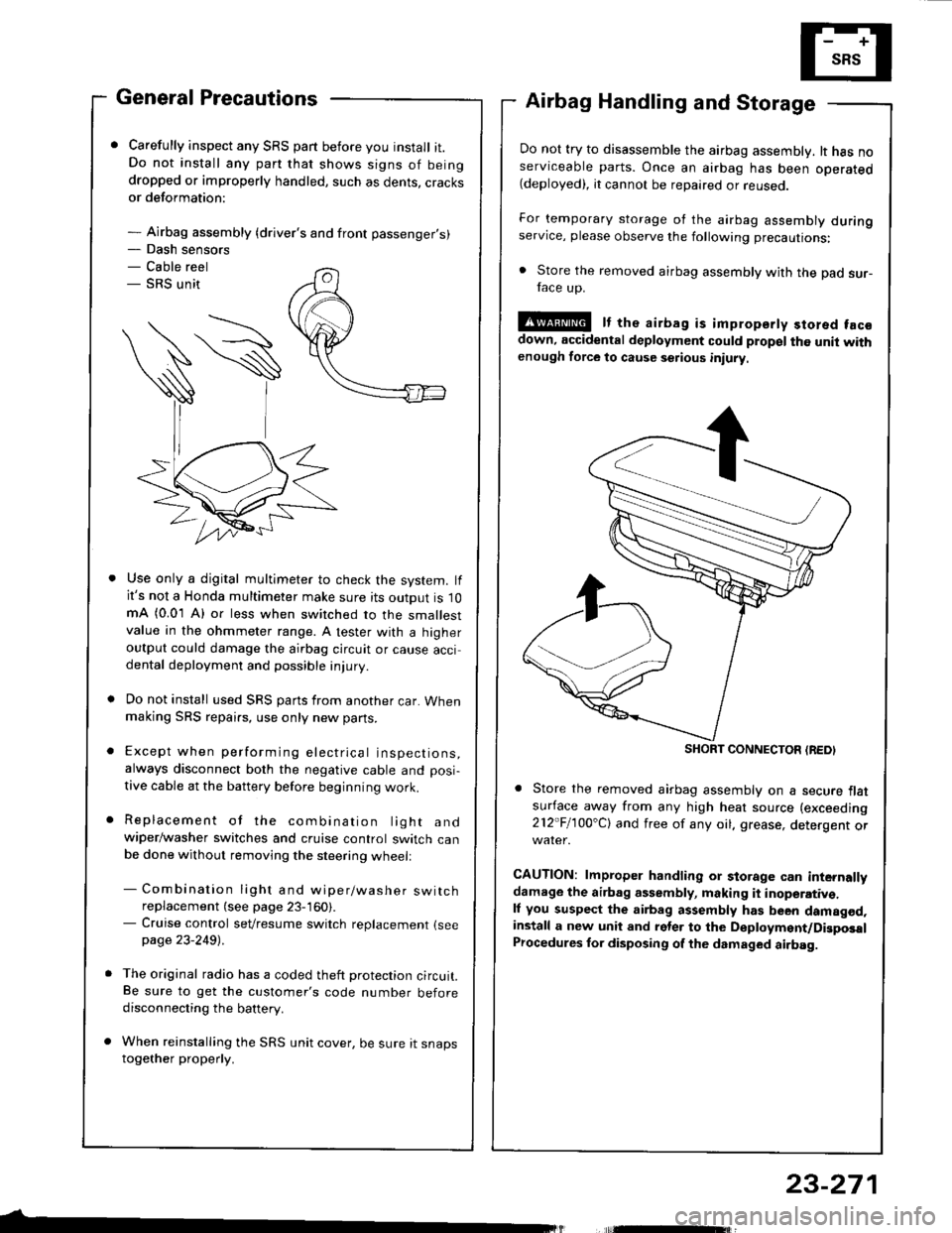
Carefully inspect any SRS part before you install it.Do not install any part that shows signs of beingdropped or improperly handled, such as dents, cracksor deformation:
- Airbag assembly {driver's and front passenger's)
Airbag Handling and Storage
Do not try to disassemble the airbag assembly. lt has noserviceable parts. Once an airbag has been operated(deployed), it cannot be repaired or reuseo.
For temporary storage of the airbag assembly duringservice, please observe the following precautions:
. Store the removed airbag assembly with the pad sur-face up.
!@ It the airbag is impropsrty stored facsdown, accidental deployment could propel the unit withenough force to cause setious iniury
Store the removed airbag assembly on a secure flatsufface away from any high heat source (exceeding
212"Fl1OO'Cl and free of any oil. grease, detergent or
CAUTION: lmproper handling or storage can internallydamage the airbag assembly, making it inoperativ€.ll you suspect the airbag assembly has been damagod,install a new unit and rgler to the Deployment/DigposalProcedures lor disposing of the dsmaged airbag.
Use only a digital multimeter to check the system. lfit's not a Honda multimeter make sure its output is 10mA (0.01 A) or less when switched to the smallestvalue in the ohmmeter range. A tester with a higheroutput could damage the airbag circuit or cause accidental deployment and possible injury.
Do not install used SRS parts from another car. Whenmaking SRS repai.s, use only new pans.
Except when performing electrical inspections,always disconnect both the negative cable and posi-
tive cable at the battery before beginning work.
Replacement of the combination light andwiper/washer switches and cruise control switch canbe done without removing the steering wheell
- Combination light and wiper/washer switchreplacement (see page 23-160).- Cruise control sevresume switch replacement {seepage 23-2491 .
The original radio has a coded theft protection circuit.Be sure to get the customer's code number beforedisconnecting the battery.
When reinstalling the SRS unit cover, be sure it snapstogether properly.
SHORT CONNECTON {REDI
23-271
Page 1377 of 1413

Supplemental Restraint System (SRSI
Wiring Precautions
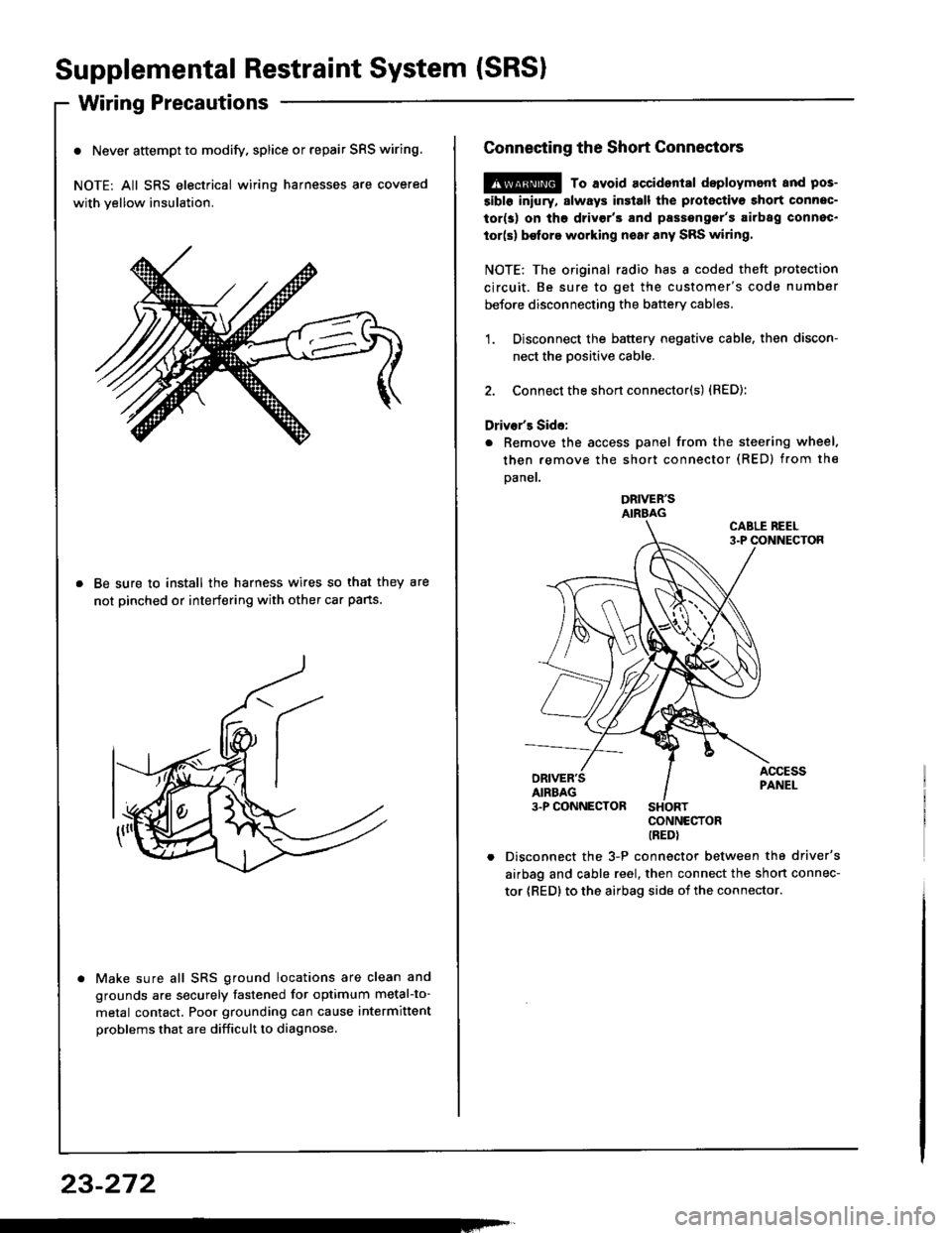
o Never attempt to modify. splice or repair SRS wiring.
NOTE: All SRS electrical wiring harnesses are covered
with yellow insulation.
Be sure to install the harness wires so that they are
not pinched or interfering with other car pans.
Make sure all SRS ground locations are clean and
grounds are securely fastened for optimum metal-to-
metal contact. Poor grounding can cause intermittent
problems that are difficult to diagnose.
23-272
Connecting the Short Connectors
@ To avoid accident8l deploymont and pos-
5ibl6 iniury, slways insiall the protectiva short connec-
tor(s) on tho drivgr'3 and passengor's airbag connec.
tor(s) be{ore working noar any SRS wiring.
NOTE: The original radio has I coded theft protection
circuit. Be sure to get the customer's code number
before disconnecting the battery cables.
1. Disconnect the battery negative cable. then discon-
nect the Dositive cable.
2. Connect the short connector(s) {RED):
Driver's Side:
. Remove the access panel from the steering wheel.
then remove the short connector (RED) from the
Daner.
DRIVER'SAIRBAG
CONNECTORIREDI
Disconnect the 3-P connector between the driver's
airbag and cable reel, then connect the short connec-
tor {RED} to the airbag side oi the connector.