Page 1078 of 1413
Troubleshooting
Condenser Fan
BLU/YEL
View lrom wire side
Remove the condenser fan relay
and test it (see page 22-19).
Replaco the condan3ar frn rclay.
Measure the voltag€ betwe€n the
WHT wire terminal (+) and bodyground (-).
Replir opcn in tho WHT wiro bo-
twoen tha undor-hood fura/Jolay
box rnd tha condonr.rlan rclay.
Connoct the WHT and BLU/BLK
wire terminals with a jumPer
Does the condenser fan run?
Check for continuity in the BLU/
BLK wire between the condenser
Ian relay and the condenser fan
Reprir op€n in th. BLU/BLK wiro
batwcen the condenrai lan rolay
and the condcntor ftn
Check for continuity in the BLK
wire between the condenser fan
and body ground.
Check fot.n op.n in tho BLK
wire botween the condental trn
and bodv g.ound. It the wiro i3
OK, chock lor Poo. ground rt
G151.
Raplaco the condon36r fan motor.
BLK/WHT l+l
10 page 22-11
View from wire side
BLU/BLK
22-10
Page 1082 of 1413
Troubleshooting
Gompressor
R6move the comPressor clutch
refay and test it (see Page 22-19l..
Measuro the voltage bgtlveen th€
WHT wire terminal {+) and body
ground {-}.
Rap.ir op.n in ih. WHT wit.
batwaan tha undar-hood fuaa/
ralay box and thg comptaalol
clutch r.l.y.
Connect tho WHT and 8€D wire
terminals with a jumPer wire.
Disconnect the comPressor
clutch 1P connsctor.
Check for continuity in the RED
wiro botween the comPressorclutch relay and the comPressorclutch.
Replir op.n in th. REO wi.c
batwaan tho comPrdaor clutchrol.y and the compr.33oi clulch.
Inapact tha compter3oa clutchclelranca !nd ihc comPacaaorctutch fi€ld coil {!.. P.9.22'32}.
BLK/YEL {+l
WHT l+l
BLK/RED
View from wir€ side
View lrom wire side
To page 22-15
22-14
Page 1083 of 1413

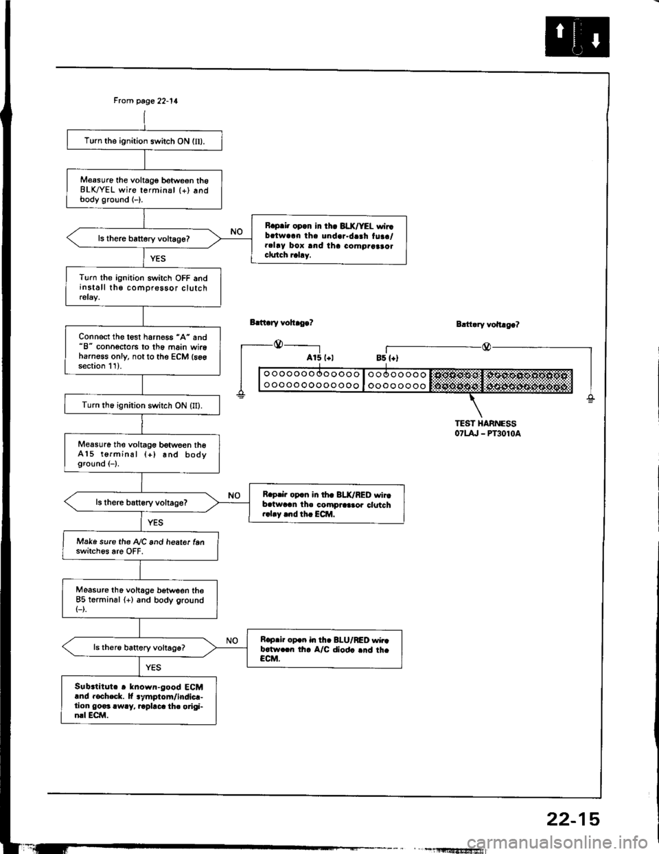
Frcm page 22-11
Bdt ry vohro.?
_@_____-l
Turn the ignition switch ON (lI).
M€asure the voltage betweon th6BLK/YEL wire terminsl {+) andbody ground (-).
R.p.i. opcn in th. 3LX/YEL wirrbalwarn tha undar.da3h tuaa/.clay box and iha como.aaao.clutch rahy.
ls there battery voltage?
Turn the ignition switch OFF andinstall the comprossor clutchrelay.
Connect the test harness "A" and"8" conoectors to th6 main wireharness only, not to the ECM (s6gsection 11).
Turn th6 ignition switch ON (II).
Measure the voltagG between theA15 terminal (+) and bodyground (-1.
R.prir op.n in th. BLK/RED wirtb.twran the compraa.or clotch..1.y .nd th. ECM.
Make sure the A/C and heate. tenswitch6s are OFF.
Measure tho voltage b€tween the85 terminsl (+) and body ground(-).
R.p.ir op.n in th. BI-U/RED wir.b.tw.rn th. A/C diod. .nd th.CCM.
Sub.titute r known-good ECMand rocheck. lt lymptom/indicr-tion go€3 rwry, rapbca th. origi-nrl ECM.
Blttary vohago?
r_--@_Bs {+)
TEST HARNESS07t4, - PT3010a
" , -1llltf,'tfrSfiiwiafi
22-15
Page 1087 of 1413
A/C Thermostat
Test
Connect battery power to terminal C and ground termi-
nal B, and connect a test light between terminals A and
NOTE: Use a 12 V, 3W- 18Wtest light.
Dip the A-/C thermostat into a cup filled with ice water,
and check the test light.
The light should go off at 37"F (3"C) or less. and should
come on at 39"F (4"C1 or more.
lf the light doesn't come on and go off as specified,
replace the Ay'C thermostat.
There should be continuity between the A and C term!nals when power and ground are connected to the Band D terminals.
There should be no continuity when power is discon-nected.
. Radiator fan relay
Condenser fan relay
Compressor clutch relay
Relays
a
a
,I Ir-b
InP.I I
12V.3W-18W
ABC
22-19
Page 1107 of 1413

Electrical
Special Tools
Troubleshooting
Tips and Precautions ................................ 23-3Five-stop Tloubleshooting ..............,...-..-... Z3-sSchematic Symbols ................................_. 23-6wire Color Cod€s ..................................... 23-6Relay and Control Unit Locations
Engine Compartment .........,............ ... --. 23-7Dsshboard and Door ..,,......................... 23-gDashboard and Floor ............................. 23-t OOuaner Panel .....-.....23-12Connector ldentification and WireHarness Routing ........ 23-i 3
Index to Circuits and Systems
Airbag ............... ...-..-... 2g-26sAir Conditioning ....,.. Section 2lAltelnator ......_.............. 23-99Anti-lock Brake Systsm (ABS) Section 19Automatic Transmission Section 14Battery .............. .......... 23-66Chafging System ........... 23-98rCigalstte Lighter .....................-...-......-..-.. Z3-2O4Cfock ................. ..........23-197rcruise Controf .......--..-... 23-242Distributor .................... 23-87Fan Controls ................. 23-1ogFuel and Emissions ... Section 1i*Fuses
Under-dash Fuse/Relay Box ................... 23-48Undor-hood ABS Fuse/Retay Box ............ 23-51Under-hood Fuse/Relay Box,.................. 23-52rGauges
Engine Coolant Temperature {ECT)Gauge ................ ..23-126Fuef cauge ............... 2g-123'Gauge Assembly ....--.23-113Speedometer .....-...,,. 23-114Tachometer .....,.....-.. 23-114Ground Distribution ........ 23-60Heater ,,,........,.... ..... Section 2lrHorn ................. ........... 23-199*fgnition Switch ............. 23-70fgnition Syst6m .......-..-.. 23-A7lgnition Timing .............. 23-89Indicator Lights"A/T Gear Position .............. ................... 23-1 32B1ak6 System ...,..,..-.23-127Engine Oil Pressura .............................. _ 23-1 51Low Fuel ............ ......23-125Malfunction Indicator Lamp {MlL} ...,,. Section I l
tfnteglated Control Unit ...29-144*lnterlock System ...................................... 23-1 3gLights, Exteriol
Back-up Lights ........... 23-179Brake Lights .............. 23-t8ltDaytime Running Lights {Csnada} ........... 23-156Front Palking Lights ............................. 23-1 65Flont Side Marker Lights ....................... 23-165Front Turn Signal Lights ........................ 23-1 65*Hazard Warning Lights .........................- 2g-1A4Headlights ................. 23-t6tLicense Plate Lights .............................. 23-1 69Taillights(Harchback) .......... 23-166
{Sedan) .............. .. 23-167Lights. Inteliol
Cargo Area Light {Hatchback) ...... -.. -.. -... 23-177Ceifing Light ........-..-.23-175
Dash Lights Blightness Controt .............. 23-t70Glove Box Lighr ................................... 23-1 69Spotfighr ............ ....-.23-174Trunk Light (Sedanl ............... .............. - 23.-177*Lighting Sysrem .......-.-... 23-152:Moonroof ,,.,.......,..,,,,,.-.23-211PGM-FI Systom ........ S€crion 11Power Distribution .,.-..--..23-54Power Door Locks .............,,..................... 23-233Power Mirors ..,..,....-...- 23-216Power Relays ...........,..... 23-68Power Windows ............ 29-222*Rear Window Defogger ........,... ..........,..... - 23-20,6Reminder Systems
Key-in Remindel System ....,.............,.... 23-1 50Lights-on Reminder System ................... 23-l 5f*Maintenance Reminder system ..,,.... -.. - -. 23-.1 2gSeat Belt Reminder System ..................- 23-125*Side Markel/Turn Signal/Hazard
Ffasher System .,..,..-.23.-1A4Spark Pfugs .........-...-..... 23-97Starting System ....,,.....-. 23-73*Stereo Sound System ...,.......................,,.. 23-l gg
Supplemental Restraint System {SRS} ......... 23-265Vehicfe Speed Sensor {VSS) .............--..-.... 23-122*Wiper/Washer Systom ...............--.........-..- Zg-254
rRead SRS pi€cautions on Page 23-271 betore workingin these areas.
-+
Page 1109 of 1413

Troubleshooting
Tips and Precautions
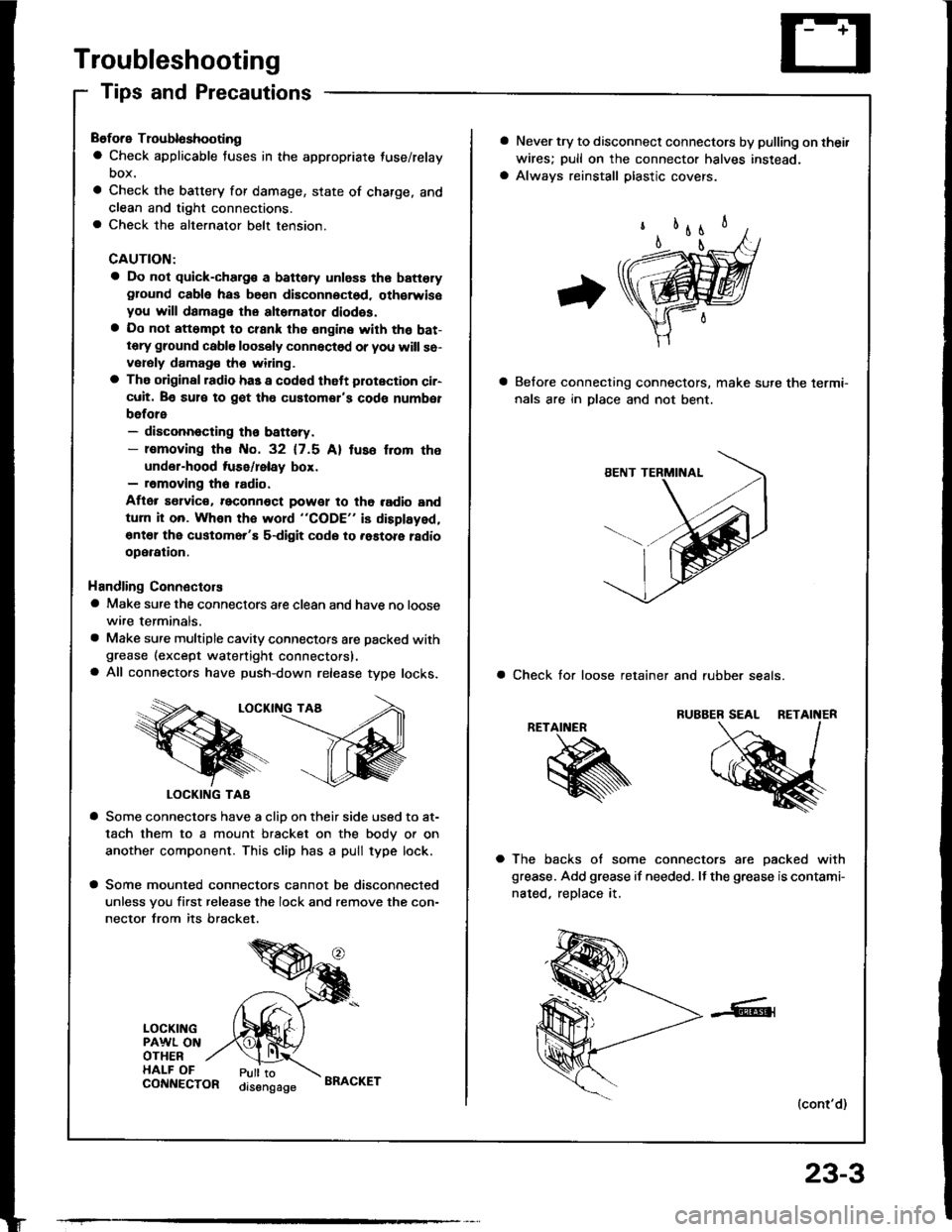
Before Troubloshooting
a Check applicable fuses in the appropriate fuse/relay
DOX.
a Check the battery for damage, state of charge, and
clean and tight connections.a Check the alternator belt tension.
CAUTION:
a Do not quick-charg€ a battery unless the batteryground cabla has be€n disconnoctsd. oth€rwisoyou will damage the alternator diodss.a Do not att6mpt to crank the engine with the bat-tery ground cable loosely connectsd or you will se-vorsly damag€ tho widng.
a The original radio has a codod thatt plotection ci.-cuit. Be sul€ to got tho customor's code numbet
before- disconnecting th€ battery.- lomoving tho No. 32 (7.5 Al tuso f.om the
under-hood tuse/lelay box.- removing tho radio.
Aflor s€lvic€. reconn€ct powet to tho radio and
turn it on. Whon the word "CODE" is displayed,
€nt€l the customer'E s-digit codo to .astore ladio
operation.
Handling Connectors
a Make sure the connectors are clean and have no loose
wire terminals.
a Make sure multiple cavity connectots are packed withgrease (except watertight connectors).a All connectors have push-down release type locks.
LOCKII{G TAA
LOCKING TAB
a Some connectors have a clio on their side used to at-
tach them to a mount bracket on the body or on
another component. This clip has a pull type lock.
a Some mounted connectors cannot be disconnected
unless you first release the lock and remove the con-
nector from its bracket.
LOCKINGPAWL ONOTHERHALF OFPull toorsengageCONNECTORBRACKET
23-3
a Never try to disconnect connectors by pulling on thei.
wires; pull on the connector halves instead.
a Always reinstall plastic covers.
Belore connecting connectors, make sure the lermi-
nals are in Dlace and not bent.
a Check tor loose retainer and rubber seals.
RETAINER
a The backs of some connectors are oacked with
grease. Add grease if needed. It the grease is contami-
nated, reDlace it.
(cont'd)
Page 1112 of 1413

Troubleshooting
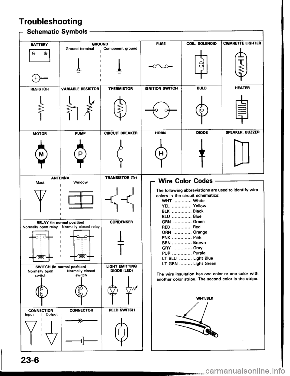
Schematic Symbolsym
BATTERY
le @l
ll
e-
GROIGround terminal
I
,ltDComponont ground
I
FUSECOIL, SOLENOID
H
CIGANETTE LIGHTER
A
t+j
RESISTOR
+
VARIABLE RESISTOR
ilH
THERMISTOR
e
tcNtTtol{ swTcH
-1o oF
BULB
e
HEATER
H
MOTOR
a
PUMP
0
CIRCUIT BREA(ER
I
T
HORI'
+
DIODE
+
SPEATER, BUZZER
D
Mast
Y
ANTIINNATRA SISTOR lTrl
II
Wire Golor Codes
The tollowing abbreviations are used to identity wire
colors in th€ circuit schematics:
wHT ............ White
YEL .............. Y6llow
BLK .............. Black
BLU .............. Blue
GRN ............. Green
RED.............. Red
ORN ............. Orange
PNK .............. Pink
BRN .............. Brown
GRY ............. Gray
PUR .............. Purple
LT BLU ......... Light Blue
LT GRN ......... Light Gr€en
The wi.e insulation has one color or one color with
another color stripe. The s€cond color is the stripe.
WHT/ALK
,/t,/l./l--
R
RELAY {ln noNormally open relayrmal poritionl
Normally closed relay
*Gt-i- |
lll
l'*^f
CO'IDENSER
I
T
SWITCH (ln ngrmal position)
Normally open ' Normally closodswitch I switch
til
@@
lil
LIGHT EMITTINGDIODE (LEDI
A[,
TT
CONNEInpur
f7
I
CTIONOutput
I\/
CONNECTON
--+>-
tl'l
BEED SWITCH
A
lril
Y
23-6
Page 1113 of 1413
Relay and Control Unit Locations
Engine Compartment
ABS PUMP MOTORRELAY
ELECTRICAL LOAD DETECTOR (ELD)
UNDER.HOODFUSE/RELAY BOXUNOER-HOOD ABSFUSE/BELAY BOX
. ABS FRONT FAIL SAFE RELAY
I Wirc colors: WHT/GRN, BRN/BLK, IIYEL/GRN snd BLK I
. ABS REAR FAIL SAFE RELAY
I Wire colors: WHT, BLU/BLK, II YEL/GRN and BLK I
. CONDENSER FAN RELAY
I Wi]o colors: WHT, BLUi BLK, II BLKMHT and 8LU/YEL I
. A/C COMPRESSOR CLUTCH RELAY
I Wiro colors: WHT, RED, II BLK/YEL and BLK/RED I
23-7