Page 1037 of 1413

Heater and Air Conditioning
Heater ........ 21-1
Air Conditioning .......... ..22-1
SUPPLEMENTAL RESTRAINT SYSTEM {SRS}
The Integra SRS includes a driver's airbag, located in the steering wheel hub. In addition. all models except the
RS model for Canada have a front passenge.'s airbag located in the dashboard above the glovs box. Information
necessary to safely service the SRS is included in this Service Manual. ltems msrk€d with an asterisk (') on the
conlents page include, or are located near, SRS components. Servicing, disassembling or,eplacing thes€ items
will require special precautions and tools, and should therefore be done by an authorized Acura dealer.
a To avoid r6nd6dng tho SRS inoporativo. which could lead to personal injury or dealh in tho svont ot a sevele
frontal collision, all SRS servica work musl b€ portormed by an authorized Acura dealer.
a lmpropor sorvico procaduro3, including incorrect romoval and installatlon of tho SRS, could load to porsonal iniu-
ry causod by uninlonlional activation of tho ailbag8.
a All SRS eloctdcal widng harnossos are covored with yollow in3ulation. Relatsd compononts a.o locatod in tha
stsering column, flont console, daehboard, and dashboafd low6r pan6l, and in lhe dsshboa.d above lh€ glove
box. Do not uao electdcal tost equipmont on theae circuhs.
NOTE: The original radio has a coded theft protection circuit. Be sure to get the customer's code number beto.e
- disconnecting the battery.- removing the No. 32 (7.5 A) luse from the under-hood fuse/relay box.- removing the radio.
After service, reconnect power to the radio and turn it on. When the word "CODE" is displayed, enter the cus-
tomer's 5-digit code to restore radio operation.
Page 1038 of 1413

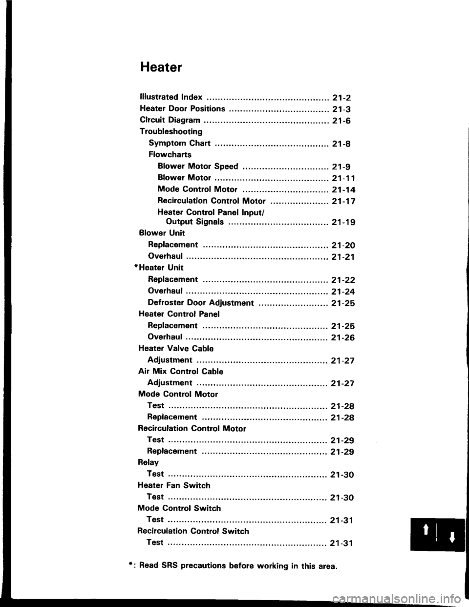
Heater
lflustrated Index ............. .........21-2
Heater Door Positions .........,..,. 21-3
Circuit Diagram ....................... 21-6
Troubleshooting
Symptom Chart ............. ......21-8
Flowcharts
Blower Motor Speed ............................... 21 -9
Bfower Motor .........,..,,,,,.. 21-11
Mode Control Moto. ............ ................... 21 -14
Recircufation Control Motor ......,...,.,,,.,.... 21 -17
Heater Control Panel Input/
Output Signals ..............21-19
Blower Unit
Repfacoment ....................... 21-20
Overhaul .......21-21
+Heater Unit
Repfacement ....................... 21-22
Overhaul .......21-24
Def roster Door Adjustment ...,............. ......,, 21 -25
Heatel Control Panel
Repfacoment ....................... 21-25
Overhaul .......21-26
Heater Valve Cable
Adjustment ...21-27
Air Mix Control Cable
Adjustment ... 21-27
Mode Control Motol
Test .............. ..................... 21-2e
Repfacement ..,..............,,,,.. 21-28
Recirculation Control Motor
Test .............. ..................... 21-29
Repfacement ....................... 21-29
Relay
Test .............. ..................... 21-30
Heater Fan Switch
Test .............. ..................... 21-30
Mode Control Switch
Test .............. ..................... 21-31
Recilculation Control Switch
Test .............. ..................... 21 -31
*: Read SRS precautions before working in this area.
Page 1048 of 1413
Blower Motor
View from wire side
View from wire side
Blowor motor doos noi iun at all.
check the No. 37 (4o A) fuse intho under-hood fuse/relay box.
At th€ blower motor 2P connec-tor, connect the BLU/8LK wirc ter-minal to body ground wath ajumpe. wire.
Turn the ignition switch ON (ll).
Does the blower motor run?
Disconnect the blower motor 2Pconnector, and measure the vol-tago between the ELU/wHT wireterminal {+} and body ground
{-}.
Turn the ignition switch OFF.
Remove the blower motor relavfrom the under-hood fuse/relavbox and test it {see page 21-3O}.
Roplaco tho blowor motor rolay.
Measure the voltage betwgen theNo. 1 terminal (+) and bodyground (- ).
To page 21-12
To page 2l-13
"uf"'\'
,)
(cont'dl
21-11
Page 1067 of 1413
Relay
There should be continuity b€tween the A and C termi-
nals when Dower and ground are connected to the B and
D terminals.
There should be no continuity when power is discon-
nected.
Heater Fan Switch
Check for continuitv bstween the terminals according to
the table below.
Terminal
PositionADBE
OFF
,lo--o
o--o
3o--o
4-o
rl
I
I
r?
21-30
Page 1071 of 1413

lllustrated Index
CAUTION:
. All SRS electrical wiring harnossos are cover€d withyellow insulation.
. B€fors disconnacting any part of the SRS wire har-ness, connsct the 3hort connsctor(s).. Replace the entirs affscted SRS harness assembly itit has an open circuit or damaged wiring.
NOTE; The original radio has a coded theft protection
circuit. Be sure to get the customer's code number
before- disconnecting the battery.- removing the No.32 (7.5 A) fuse from the under-
hood fuse/relay box.- removing the radio.
After service, reconnect Dower to the radio and turn it
on. When the word "CODE" is displayed, enter the cus-
tomer's 5-digit code to restore radio operation.
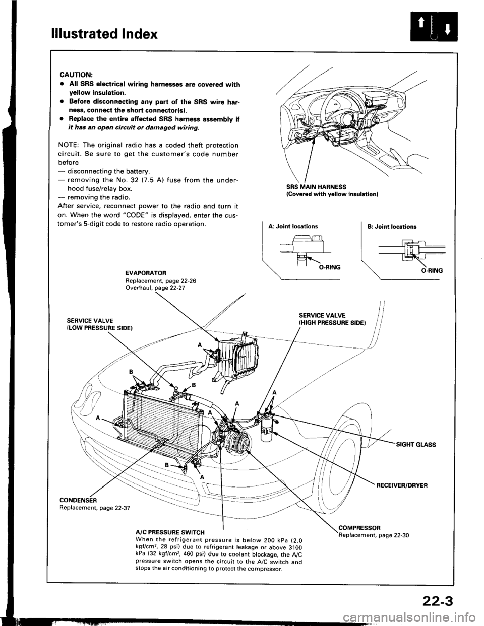
SRS MAIN HARNESSlcover€d with yellow insulationl
EVAPORATORReplacement, page 22-26Ovethaul. Oase 22.27
SERVICE VALVE(LOW PRESSURE SIDEI
SERVICE VALVEIHIGH PRESSURE SIDE)
RECEIVER/DRYER
CONDENSERReplacement, page 22,37
A/C PRESSURE SWITCHCOMPRESSORReplacement, page 22-30When the refrigerant pressure is below 200 kpa (2.0kqflcm,,28 psi) due to refrigerant leakage or above 3]OOkPa (32 kgf/cm,, 460 psi) due to coolant btockage, the A,/Cpressure switch opens the circuit to the A"/C switch andstops the air conditionang to protect the compressor.
22-3
Page 1072 of 1413
Wiring/Connector Locations
A/C DIODECONNECTOR(Loc.ted .bovo tho.ight kick p.n.ll
RADIA'OR FAN RELAY{Localed in the undel-hood fu3o/reltY box)
A/CTHERMOSTAT CONDENSERFANCONNECTOR CONNECTOR
MAIN WIRE HARNESS
A/C WIRE HARNESSCONNECTOR
RADIATOR FANCONNECTOR
A/C WIRE HARNESS
COMPRESSOR CLUTCHCONNECTORA/C PR€SSURE SWTTCHCONNECTOR
22-4
Page 1075 of 1413

Troubleshooting
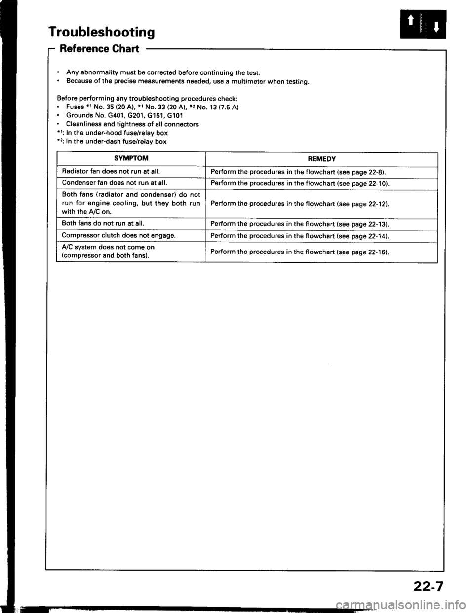
Reference Ghart
. Any abnormality must be correctsd before continuing the test.. Because of the precise measurgments needed, use a multimeter when testing.
Before performing any troubleshooting procedures check:. Fus€s .r No. 35120 A), *1 No. 33 (20 A), ), No. 13(7.5A). Grounds No. G401, G201, G'151, G101. Cleanliness and tightness of all connectors*1: In the under-hood fuse/relay box*2: In the under-dash fuse/relay box
SYMPTOMREMEDY
Radiator fan does not run 8t all.Perform the procedures in the flowchan (see page 22-8).
Condenser fan does not run at all.Perform the procedures in the flowchart (see page 22-10).
Both fans (radiator and condenser) do not
run for engine cooling, but they both run
with the Ay'C on.
Perform the procedures in the flowchan (see page 22-12).
Eoth fans do not run at all.Perform the procedures in the flowchart (see page 22-13).
Compressor clutch does not engage.Perform the procedures in the flowchart (see page 22-14).
Ay'C system does not come on
{compressor and both fans}.Perform the procedures in the flowchart (see page 22-16).
22-7
Page 1076 of 1413
Troubleshooting
Radiator Fan
Redi.to. fan doo3 not run at all.
check rhe No. 33 {20 A) fuse inthe under-hood luse/relay box.
Remove the radiator lan r€layfrom the under-hood Iuse/relaybox and test it (see page 22-19).
Raplaca tha radiator tln rahy.
Measure the voltage between theNo. 3 terminal (+) and bodyground {-}.
ls therg battery voltag€?
Connect the No. 1 and No. 3 ter-minals with a jumper wire.
Does the radiator Ian run?
Chock for continuity in the BLK./RED wire between the No. 1 ter-minal and the radiator fan.
R.p.ir opdr in th. 8LK/RED wir.batwaon th. unda.-hood fut./ralay box rnd tha radirtor f.n.
Check for continuity in th€ BLKwire between the radiator {anand body ground.
Ch.ck to..n op.n in th. BLKwirc batwaan th. rldirtor hnlnd body ground, lf tha wita i!OK, chack tor poor gtound rtG2ol lnd GiOl.
Rephco tho radi.tor frn motor.
To p3ge 22-9
22-A