Page 1097 of 1413
lllustrated lndex
CENTER BOLT
CLUTCHSETInspoc!on,page 22-32
SNAP RING AReplace.
-t COMPRESSOR COMPLETE
f-- lDo nor disassemble)
colLInspection, pag6 22 32
RELIEF VALVE
'-f
Replacement, page 22-34
22-29
Page 1098 of 1413
Compressor
Glutch Inspection
Check the plated parts ot the pressure plate tor color
changes. peeling or other damage. lf there is dam-
8ge, replace the clutch set.
Check the pulley bearing play and drag by rotating
the pulley by hand. Replace the clutch set with a new
one if it is noisv or has excessive play/drag
Measure the clearance betlveen the pulley and the
pressure plate all the way around. lf the clearance is
not within specified limits, the pressure plate must be
removed and shims added or removed as required.
Jollowing the procedure on page 22-33.
Clearrnce: 0.50 t 0.15 mm {0.02 i 0.01 inl
NOTE: The shims are available in three thicknesses:
0.1 mm, 0.3 mm and 0.5 mm.
22-32
Check resistance of the tield coil.
Fisld Coil Rosistance: 3.6 t 0.2 ohm at 68"F {20'C)
lf resistance is not within specifications, replace the
field coil.
Page 1100 of 1413

and com
it with a
a
a
a
a
4t l\-N
r-
-l/
Compressor
Clutch Overhaul (cont'dl
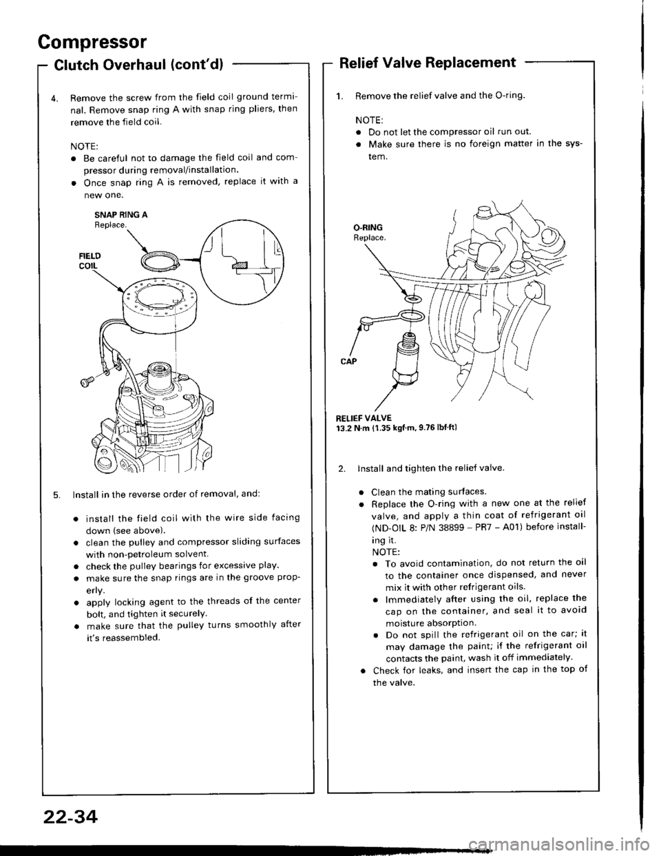
Remove the screw from the field coil ground terma-
nal. Remove snap ring A with snap rjng pliers, then
remove the field coil.
NOTE:
. Be careful not to damage the field coil
pressor during removal/installation.
. Once snap ring A is removed, replace
new one.
SNAP RING AReplace.
FIELDcorL
5. lnstall in the reverse order of removal, and:
install the field coil with the wire side facing
down (see above).
clean the pulley and compressor sliding surfaces
with non-petroleum solvent.
check the pulley bearings for excessive play.
make sure the snap rings are in the groove prop-
efly.
apply locking agent to the threads of the center
bolt, and tighten it securelY
make sure that the pulley turns smoothly after
it's reassembled.
1. Remove the relief valve and the O-ring.
NOTE:
. Do not let the compressor oil run out.
. Make sure there is no foreign matter in the sys-
tem.
RELIEF VALVE13.2 N.m {1.35 kgtm,9.76lbtftl
2. lnstall and tighten the relief valve.
Clean the mating surfaces.
Replace the O-ring with a new one at the relief
valve, and apply a thin coat of refrigerant oal
(ND-OIL 8: P/N 38899 - PR7 - A01) before install-
ing it.
NOTE:
. To avoid contamination, do not return the oil
to the container once dispensed, and never
mix it with other refrigerant oils.
. lmmediately after using the oil, replace the
cap on the container, and seal it to avoid
moisture absorption.
. Do not spill the refrigerant oil on the car; lt
may damage the painu if the refrigerant oil
contacts the paint, wash it off immediately.
Check for leaks, and insert the cap in the top of
the valve.
22-34
Page 1101 of 1413

A/C Compressor Belt
Replacement
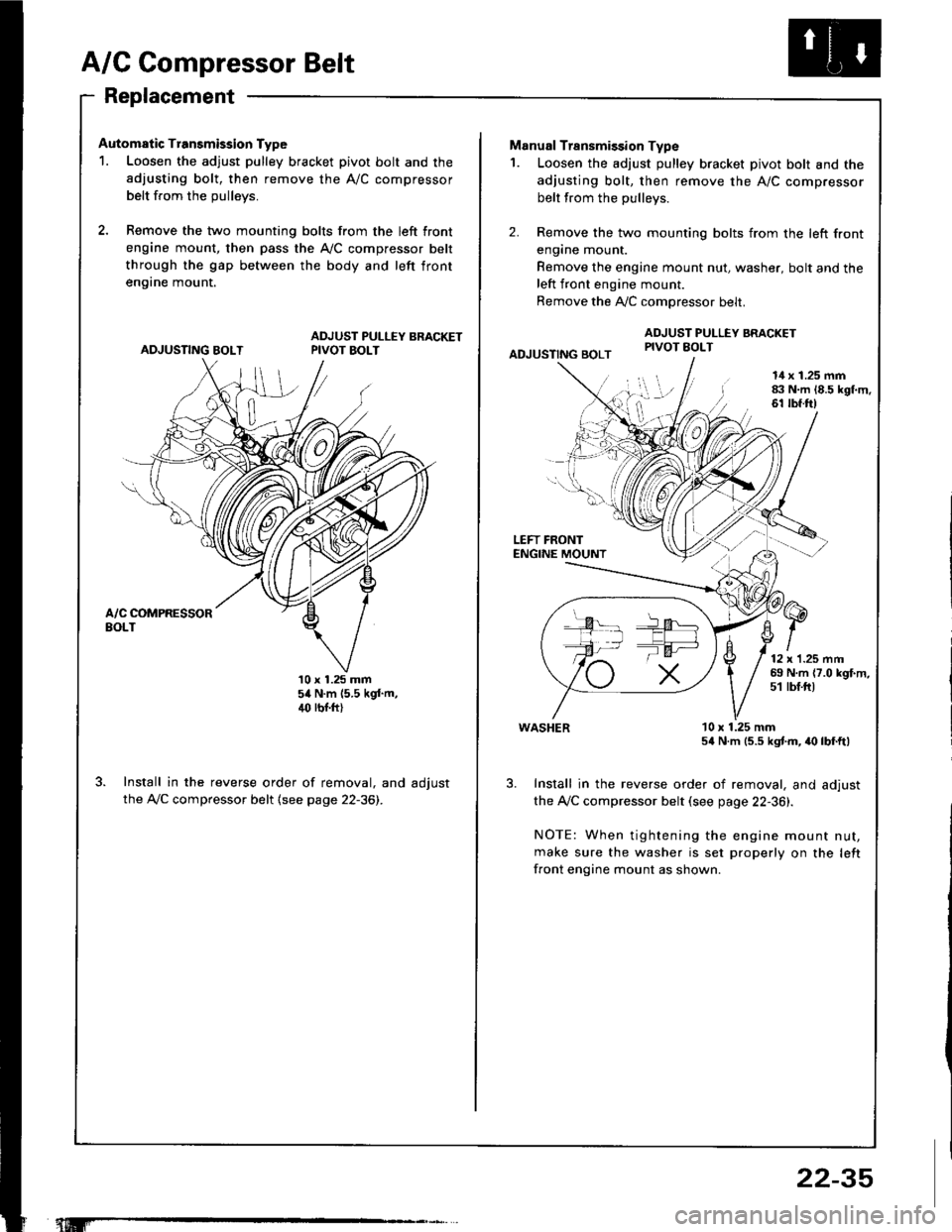
Automatic Transmission Type
1. Loosen the adjust pulley bracket pivot bolt and the
adjusting bolt, then remove the A/C compressor
belt from the oullevs.
2, Remove the two mounting bolts from the left front
engine mount, then pass the A,/C compressor belt
through the gap between the body and left front
en9rne mount.
ADJUSTING BOLTADJUST PULLEY BRACKETPIVOT BOLT
10 x 1.25 mm54 N.m (5.5 kgf.m,4(' rbr.ft)
Install in the reverse order of removal, and adjust
the A,/C compressor belt (see page 22-36).
"t.M'
22-35
-la ar-
Manual Transmission Type
1. Loosen the adjust pulley bracket pivot bolt and the
adjusting bolt, then remove the A/C compressor
belt from the pullevs.
2. Remove the two mounting bolts from the left front
engane mount.
Remove the engine mount nut, washer, bolt and theleft front engine mount.
Remove the A,./C comoressor belt.
ADJUSTING BOLT
ADJUST PULLEY BRACKETPIVOT EOLT
l!l',
I
14 x 1.25 mm83 N.m 18.5 kgl.m.61 tbf.ft)
LEFT FRONTENGINE MOUNT
12 x'1.25 mm69 N.m {7.0 kgf.m,51 tbf.ftt
WASHER
Install in the reverse order of removal, and adjust
the Ay'C compressor belt (see page 22-36).
NOTE: When tightening the engine mount nut,
make sure the washer is set properly on the left
front engine mount as shown.
10 x 1.25 mm54 N.m (5.5 kgtm, irc lbf.ft)
Page 1102 of 1413

A/C Compressor Belt
Adjustment
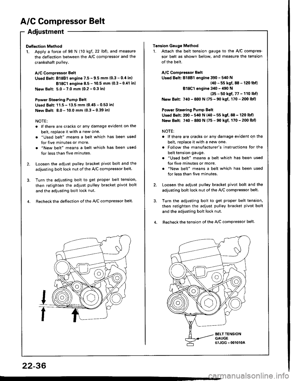
Dstlsqtion Method
1. Apply a force of 98 N (10 kgf, 22 lbf), and measure
the deflection between the A,/C compressor and the
crankshaft Dullev.
A/C Compressor Belt
Us€d Eelt: 81881 engine 7.5 - 9.5 mm (0.3 - 0.4 in)
Bl8Cl engine 8.5 - 10.5 mm (0.3 -0.11 inl
New Belt: 5.0 - 7.0 mm (0.2 - 0.3 inl
Power Stesring Pump Belt
Used Beli: 'l1.5 - 13.5 mm (0.,[5 - 0.53 inl
New 8€lt: 8.0 - 10.0 mm (0 3 - 0.39 inl
NOTE:
. lf there are cracks or any damage evident on the
belt, replace it with a new one.
. "Used belt" means a belt which has been used
for five minutes or more.
. "New belt" means a belt which has been used
for less than five minutes.
2. Loosen the adjust pulley bracket pivot bolt and the
adjusting bolt lock nut of the Ay'C compressor belt.
3. Turn the adiusting bolt to get proper belt tension,
then retighten the adjust pulley bracket pivot bolt
and the adjusting bolt lock nut.
4. Recheck the deflection of the lvc compressor belt
22-36
Tonsion Gauge Method
1. Attach the belt tension gauge to the Ay'C compres-
sor belt as shown below, and measure the tension
of the belt.
A/C Compressot Belt
Used 8€lt: Bl8Bl engine 390 - 540 N
(40 - s5 kgf, 88 - 120 lbfl
Bl8Cl ongine 3il0 - il90 N
(35 - s0 kgf, 77 - 110 lbfl
N€w Belt 7,10 - 880 N {75 - 90 kgf, 170-200lbl}
Powor Steoring Pump Belt
Used Belt: 390 - 5,{l N (40 - 55 kgf, 88 - 120 lbll
N6w Bolt: 74O - 880 N 175 - 90 kgf, 170-200lbt)
NOTE:
. lf there are cracks or any damage evident on the
belt, replace it with a new one.
. Follow the manufacturer's instructions for the
belt tension gauge.
. "Used belt" means a belt which has been used
for five minutes or more.
. "New belt" means a belt which has been used
tor less than five minutes,
2. Loosen the adjust pulley bracket pivot bolt and the
adjusting bolt lock nut of the AVC compressor belt.
3, Turn the adjusting bolt to get proper belt tension,
then retighten the adjust pulley bracket pivot bolt
and the adjusting bolt lock nut.
4. Recheck the tension of the A{/C compressor belt.
Page 1113 of 1413
Relay and Control Unit Locations
Engine Compartment
ABS PUMP MOTORRELAY
ELECTRICAL LOAD DETECTOR (ELD)
UNDER.HOODFUSE/RELAY BOXUNOER-HOOD ABSFUSE/BELAY BOX
. ABS FRONT FAIL SAFE RELAY
I Wirc colors: WHT/GRN, BRN/BLK, IIYEL/GRN snd BLK I
. ABS REAR FAIL SAFE RELAY
I Wire colors: WHT, BLU/BLK, II YEL/GRN and BLK I
. CONDENSER FAN RELAY
I Wi]o colors: WHT, BLUi BLK, II BLKMHT and 8LU/YEL I
. A/C COMPRESSOR CLUTCH RELAY
I Wiro colors: WHT, RED, II BLK/YEL and BLK/RED I
23-7
Page 1120 of 1413

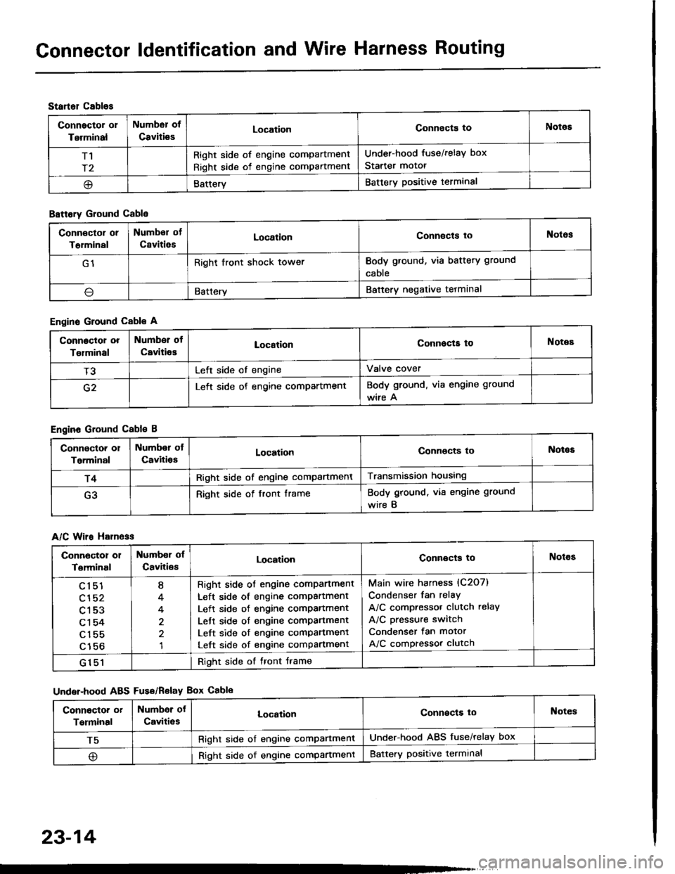
Gonnector ldentification and Wire Harness Routing
Startol cablos
Connector or
Terminal
Numbsr of
CavitiesLocationConnects toNotos
T1
r2
Right side of engine compartment
Right side of engine compartment
Under-hood fuse/relay box
Starter motor
@BatteryBattery positive terminal
B8ttory Ground Cable
Engine Ground Cable A
Engine Ground Cable B
A/C Wiro H81n6ss
Under-hood ABS Fus€/Relav Box Cablo
Conn€ctor or
T€rminal
Numbor of
CsvitiesLocationConnects toNotos
G1Right front shock towerBody ground, via battery ground
cable
\lBatteryBattery negative tetminal
Connoctor or
Tolminal
Number of
CavitiesLocationConnocta toNotes
T3Left side of engineValve cover
G2Left side of engine compartmentBody ground. via engine ground
wire A
Connoctor or
Torminal
Number ol
CavitiosLocationConnocts toNot€s
r4Right side of engine compartmentTransmission housing
G3Right side of front frameBody ground, via engine ground
wire B
Connoctor 01
Terminal
Numbor of
CavitiesLocationConnects toNotes
cl51
cl52
c153
c1 54
c155
c156
I
4
4
1
Right side ol engine comPartment
Left side of engine compartment
Left side of engine comPartment
Lett side ot engine compartment
Left side of engine comPanment
Left side of engine compartment
Main wire harness (C2O7)
Condenser fan relay
A/C compressor clutch relay
A/C pressure switch
Condenser fan motor
A/C compressor clutch
G151Right side of tront Jrame
Conngctor or
Terminal
Numbor ot
Caviti€sLocalionConnects loNotes
T5Right side of engine comPartmentUnder-hood ABS fuse/relay box
@Right side of engine compartmentBattery positive terminal
23-14
Page 1158 of 1413
Fuses
Under-hood Fuse/Relay Box
ALTERI{ATOR
fTo .ngino wlto hsrno$ {Tlolll
Not usod
r: l\lot u3.d
umborAmpsColor
nF n nn46 45 /t4 35 3l
UU U UU
n32
U
n
33
U
r:rg
U
n
42
U
n43
U
[To rldidor hn r.l.Yl
Componon! (sl 01 Clrcuit 13) Protoqtod
3115 AYEL/WHTPGM-Fl main relay
327.5 AWHT/BLUECM, TCM. Clock, Stereo radio/cassette plsyer, Maintenance reminder unit
a2204BLK/REDRadiator Jan motor
34Not used
35204WHTCondenser fan motor, A/C compressor clutch
50AWHT/REDNo. I {3O A), No. 3 (7.5 A). No. 4l2O Al, No 5 (2O A), No. 7 (2O A),
No. I (20 A) fuses
3740ABLU/lVHTBlower motor
3830ABLK/GRNRear window defogger, Noise condenser
?q50AWHT/BLKlgnition switch {BAT}
4050AWHTCombination light switch, No. 17 (1O Al fuse
41100 APower distribution
4220AWHT/GRNHorn system, Brake system, Key interlock solenoid (Aff)
4310 AWHT/GRNTurn signal/hazard.elay
44Not used
45Not used
46Not used
23-52