Page 394 of 1413

Special Tools
Rol. No. Tool NumbslDescriptionOty Page Reference
o
IA\
,6\
@
€/
o
@rt)
@
@
\9
@
@
@
@
@
@
OTGAB PF50l OO
oTGAB-PF50101
oTGAE-PG40200
oTHAC-PK4010A
oTHAE-PL50lOO
oTLAE-PX40100
OTLAJ PT30l OA
OTMAJ-PY4O'I 1A
oTMAJ-PY40120
oTPAZ -OO10100
07406-OO20003
o7406 0070000
07736 A01000A
o7746-O010100
o7746-O010500
07746-OO10600
07746 0030100
o7749-O010000
07947-6340500
Mainshatt Holder
Clutch Spring Compressor Bolt Assembly
Housing Puller
Clutch Spring Compressor Attachment
Clutch Spring Compressor Attachment
Test Harness
A/T Oil Pressure Hose, 221O mm
A/T Oil Pressure Adapter
SCS Short Connector
A/T Oil Pressure Gauge Set w/panel
A/T Low Pressure Gauge w/panel
Adjustable Bearing Puller, 25-40 mm
Attachment, 32 x 35 mm
Attachment, 62 x 68 mm
Attachment, 72 x 75 mm
Driver, 40 mm l.D.
Driver
Oriver Attachment
'I
I
1
1,1
1
1
1,|
1
1
1
1
1
I
I'I
1
14-1 1 1.160
14-144,147
14-1 1 3
14- 144,147
14 144,'t47
14-49,90
14-94
14-94't 4-44
14-94
14-94
14-150,151
14-139,140
14-140.1 50,1 51,1 52, 1 53
14-150,152
14-134
1 4-1 39,'140, 1 50.1 51,1 52
14,150
Edrn$r--€
o
a)
a6l@o
@@@@(r)
*@ Must be used with commercially available 3/8 in. x 16 threads/in. slide hammer.
@
14-2
Page 439 of 1413
A/CCOMPRESSORCLUTCHREI.AY
. VEHICI.E SPEEDSENSOR. SPEEOOMETER
SERVICE CHECKCONNECTOR
D9 013 011 Dl6 D3 D6 D7
TMNSMISSION CONTROL MODULE {TCM}
Dls 019
/8tK'HBOTfLE ENE'NEPostto^l coolAlvrSENSOR TEMPERA.TURESENSOR
Dl2
D5 A25 A26
A5 A3I
I.OCK'UP CONTROLSOLENOID VATVESHIFTCONTROLSOLENOIO VALVE
COUNTERSHAFTSPEEO SENSORMAINSHAFISPEED SENSOR
A3A5A9A1:421
A6A8A1(,/1,/1,/A1t
TCM T6rmin6l Locations
14-47
Page 472 of 1413
Electrical Troubleshooting
Troubleshooting Flowchart {cont'dl
. Lock-up clutch does not haveduty operation (ON -OFF).. Lock-up clutch does not engage.
In3poction ol ths A/C aign6l.
TLrrn the blower switch ON.
Push the A/C switch ON.
Soe Air Condilioning inspoctionlsee rection 221.
Disconnect the 26P conneclorfrom the TCM.
Measure the voltage between theA22 {BLK/RED) and A25 (8RN/
BLKI or A26 IBRN/BLK) terminals.(A/C compressor OFFI
Repair opon in 8LK/RED wiio b6-twoon lho A22 torminal and A/Ccomprossor clulch rel6y.
. A/C aignal ls OK.. Chock lor looso TCM connec-toB. lf n6co$ary, substitute aknown-good TCM and rschock.. Inrpoct tho 6ir condhioning lsooloction 221.
BR /ALK
Page 535 of 1413
Disassembly
Clutch
Remove the snap ring. then.emove the clutch endplate, clutch discs and plates.
SNAP RII{G
2. Remove the disc spring.
2ND CLUTCH
otsc sPfit c
DISC SPBING
1ST, 3RD, 4TH .ndl ST.HOLD CLUTCH
14-144.
SPNING
3. Install the sDecial tools as shown.
CLUTCH SPRIT{GCOMPRESSORATTACHME ToTLAE-PX40100
cLuTcH spnr cCOMPNESSORATTACHME ToTHAE-Pr60tOO
CLUTCH SPRII{CCOMPNESSORATTACHi'ENTOTLAE-PX,l{,TOO
CLUTCH SPBII{GCOMPRESSORATTACHMEI{ToTHAE-Pt50100
Page 538 of 1413
5, Install the special tools as shown.
CLUTCH SPRINGCOMPNESSORBOLT ASSEMBLYoTGAE-FG40200
CLUTCH SPRINGCOMPRESSORAOLT ASSEMBLY07GAE-PG40200
CLUTCH SPRINGCOMPRESSORATTACHMENT07LAE-PX40100
CLUTCH SPRINGCOMPRESSORATTACHMENToTHAE-Pl50100
CLUTCII SPRINGCOMPRESSORATTACHMENToTLAE-PX40100
CLUTCH SPRIIIGCOMPRESSORATTACHMENToTHAE-Pl50100
rr{
CAUTION: lf €ithor end of the comprossor attach-
ment is set over an area of the spring rotainer which
iE unsupported by tho retum spring, the latainer may
bo damaged.
6, Compress the return spring.
(cont'd)
Do not set here.
RETURN SPRING
14-147
Page 1069 of 1413
Air Conditioning
*Evaporator
Repf acement .........22-26
Overhauf ................ 22-27
Compressor
Description ............ 22-28
fffustrated fndex ............................... 22-29
Replacement .........22-30
Cf utch lnspection ....................... ...... 22-32
Cf utch Overhaul ............................... 22-33
Ref ief Vaf ve Replacement ............... 22-34
A/C Compressor Belt
Repf acement .........22-35
Adiustment ............22-36
Condenser
Replacement ......... 22-37
A/C System Service
Evacuation ....,.......,22-38
Charging ................ 22-39
Leak Test ...............22-40
+: Read SRS precautions before working in
this area.
Page 1071 of 1413

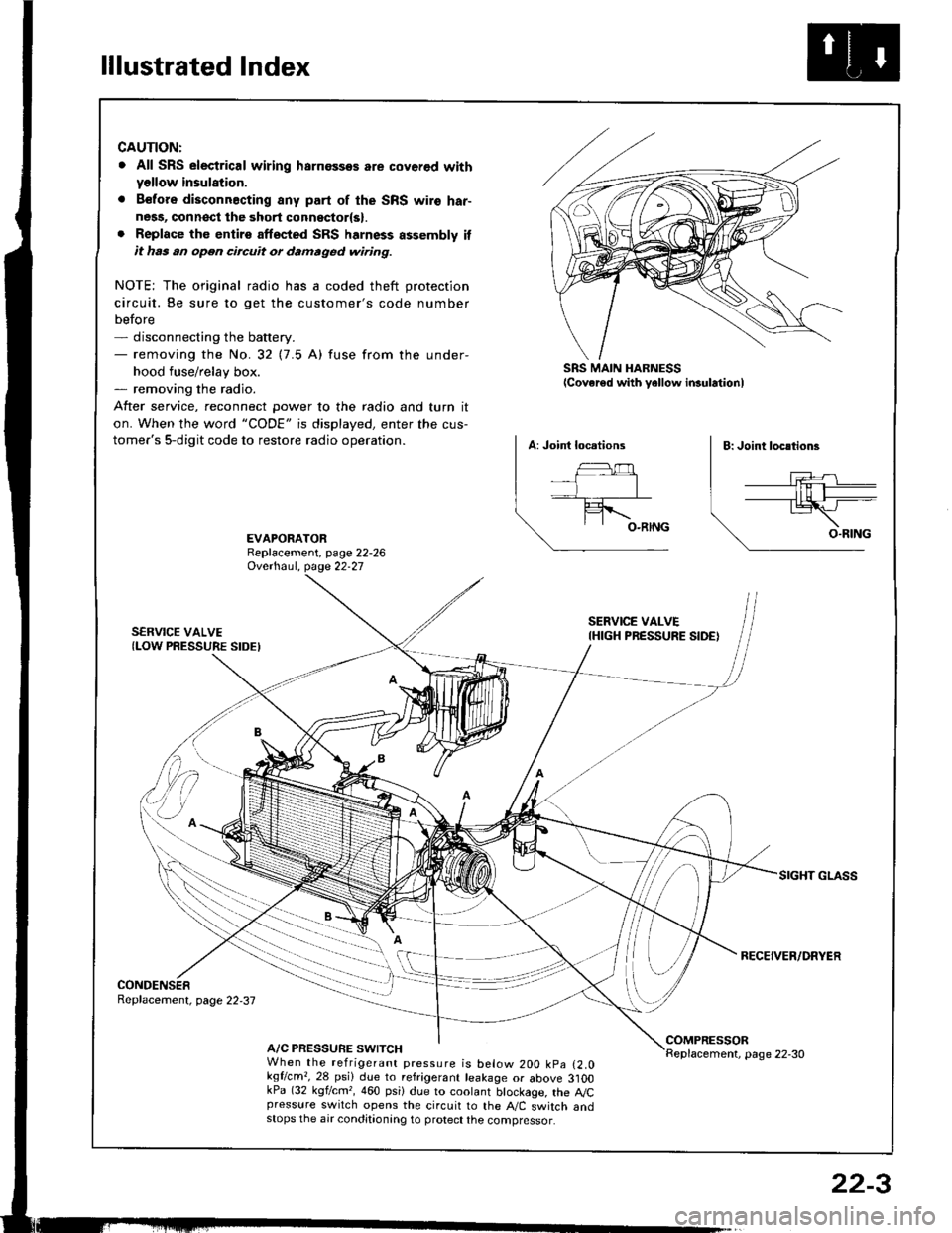
lllustrated Index
CAUTION:
. All SRS electrical wiring harnossos are cover€d withyellow insulation.
. B€fors disconnacting any part of the SRS wire har-ness, connsct the 3hort connsctor(s).. Replace the entirs affscted SRS harness assembly itit has an open circuit or damaged wiring.
NOTE; The original radio has a coded theft protection
circuit. Be sure to get the customer's code number
before- disconnecting the battery.- removing the No.32 (7.5 A) fuse from the under-
hood fuse/relay box.- removing the radio.
After service, reconnect Dower to the radio and turn it
on. When the word "CODE" is displayed, enter the cus-
tomer's 5-digit code to restore radio operation.
SRS MAIN HARNESSlcover€d with yellow insulationl
EVAPORATORReplacement, page 22-26Ovethaul. Oase 22.27
SERVICE VALVE(LOW PRESSURE SIDEI
SERVICE VALVEIHIGH PRESSURE SIDE)
RECEIVER/DRYER
CONDENSERReplacement, page 22,37
A/C PRESSURE SWITCHCOMPRESSORReplacement, page 22-30When the refrigerant pressure is below 200 kpa (2.0kqflcm,,28 psi) due to refrigerant leakage or above 3]OOkPa (32 kgf/cm,, 460 psi) due to coolant btockage, the A,/Cpressure switch opens the circuit to the A"/C switch andstops the air conditionang to protect the compressor.
22-3
Page 1072 of 1413
Wiring/Connector Locations
A/C DIODECONNECTOR(Loc.ted .bovo tho.ight kick p.n.ll
RADIA'OR FAN RELAY{Localed in the undel-hood fu3o/reltY box)
A/CTHERMOSTAT CONDENSERFANCONNECTOR CONNECTOR
MAIN WIRE HARNESS
A/C WIRE HARNESSCONNECTOR
RADIATOR FANCONNECTOR
A/C WIRE HARNESS
COMPRESSOR CLUTCHCONNECTORA/C PR€SSURE SWTTCHCONNECTOR
22-4