1994 HONDA INTEGRA Air condition
[x] Cancel search: Air conditionPage 1106 of 1413
A/C System Service
Leak Test
Only use service equipment that is U.L.-listed and is cer-
tified to meet the requirements of SAE J2210 to remove
HFC-134a (R-134a) from the air conditioner system.
CAUTION: Exposura to air condition ratrigerant and
lubaicant vapor or mist can irritato oyes. nose and
throat. Avoid br€athing tho sir conditionsr reftigolant
and lubricant vapor or mist.
lf accidental svstem discharge occurs, ventilate work
area before resuming service.
R-134a service equipment or vehicle air conditioner sys-
tems should not be pressure tested or leak tested with
comoressed air.
@ some mixturos ot air and R'13'la have
b.6n shown to b€ combustible at glsvated pressur€s
and can result in firo or sxplo3ion causing iniury or
proporty damage. Ngvar uso compress€d tir to pro33ure
tost R-134a $rvics oquipmont or vohicl€ air Gonditionsr
systcms.
Additional health and satetY information may be ob-
tained from the refrigerant and lubricant manufactures'
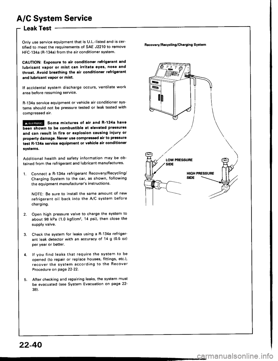
1. Connect a R-134a retrigerant Recovery/Recycling/
Charging System to the car. as shown, following
the equipment manufacturer's instructions.
NOTE: Be sure to install the same amount of new
refrigerant oil back into the A/C system before
chargtng.
2. Open high pressure valve to charge the system to
about 98 kPa (1.0 kgf/cm'�, 14 psi), then close the
supply valve.
3. Check the system for leaks using a R-134a refriger-
ant leak detector with an accuracy of '!4 g {0.5 oz)
per year or better.
4. lf you find leaks that require the system to be
opened (to repair or replace houses, fittings, etc.),
recover the system according to the Recover
Procedure on page 22-22.
5. Aiter checking and repairing leaks, the system must
be evacuated (see System Evacuation gn page 22-
38).
Rocov.ry/R.cycling/Ch.tging Sy3tcm
LOW PRESSURESIDE
HIGHSIDE
22-40
Page 1107 of 1413

Electrical
Special Tools
Troubleshooting
Tips and Precautions ................................ 23-3Five-stop Tloubleshooting ..............,...-..-... Z3-sSchematic Symbols ................................_. 23-6wire Color Cod€s ..................................... 23-6Relay and Control Unit Locations
Engine Compartment .........,............ ... --. 23-7Dsshboard and Door ..,,......................... 23-gDashboard and Floor ............................. 23-t OOuaner Panel .....-.....23-12Connector ldentification and WireHarness Routing ........ 23-i 3
Index to Circuits and Systems
Airbag ............... ...-..-... 2g-26sAir Conditioning ....,.. Section 2lAltelnator ......_.............. 23-99Anti-lock Brake Systsm (ABS) Section 19Automatic Transmission Section 14Battery .............. .......... 23-66Chafging System ........... 23-98rCigalstte Lighter .....................-...-......-..-.. Z3-2O4Cfock ................. ..........23-197rcruise Controf .......--..-... 23-242Distributor .................... 23-87Fan Controls ................. 23-1ogFuel and Emissions ... Section 1i*Fuses
Under-dash Fuse/Relay Box ................... 23-48Undor-hood ABS Fuse/Retay Box ............ 23-51Under-hood Fuse/Relay Box,.................. 23-52rGauges
Engine Coolant Temperature {ECT)Gauge ................ ..23-126Fuef cauge ............... 2g-123'Gauge Assembly ....--.23-113Speedometer .....-...,,. 23-114Tachometer .....,.....-.. 23-114Ground Distribution ........ 23-60Heater ,,,........,.... ..... Section 2lrHorn ................. ........... 23-199*fgnition Switch ............. 23-70fgnition Syst6m .......-..-.. 23-A7lgnition Timing .............. 23-89Indicator Lights"A/T Gear Position .............. ................... 23-1 32B1ak6 System ...,..,..-.23-127Engine Oil Pressura .............................. _ 23-1 51Low Fuel ............ ......23-125Malfunction Indicator Lamp {MlL} ...,,. Section I l
tfnteglated Control Unit ...29-144*lnterlock System ...................................... 23-1 3gLights, Exteriol
Back-up Lights ........... 23-179Brake Lights .............. 23-t8ltDaytime Running Lights {Csnada} ........... 23-156Front Palking Lights ............................. 23-1 65Flont Side Marker Lights ....................... 23-165Front Turn Signal Lights ........................ 23-1 65*Hazard Warning Lights .........................- 2g-1A4Headlights ................. 23-t6tLicense Plate Lights .............................. 23-1 69Taillights(Harchback) .......... 23-166
{Sedan) .............. .. 23-167Lights. Inteliol
Cargo Area Light {Hatchback) ...... -.. -.. -... 23-177Ceifing Light ........-..-.23-175
Dash Lights Blightness Controt .............. 23-t70Glove Box Lighr ................................... 23-1 69Spotfighr ............ ....-.23-174Trunk Light (Sedanl ............... .............. - 23.-177*Lighting Sysrem .......-.-... 23-152:Moonroof ,,.,.......,..,,,,,.-.23-211PGM-FI Systom ........ S€crion 11Power Distribution .,.-..--..23-54Power Door Locks .............,,..................... 23-233Power Mirors ..,..,....-...- 23-216Power Relays ...........,..... 23-68Power Windows ............ 29-222*Rear Window Defogger ........,... ..........,..... - 23-20,6Reminder Systems
Key-in Remindel System ....,.............,.... 23-1 50Lights-on Reminder System ................... 23-l 5f*Maintenance Reminder system ..,,.... -.. - -. 23-.1 2gSeat Belt Reminder System ..................- 23-125*Side Markel/Turn Signal/Hazard
Ffasher System .,..,..-.23.-1A4Spark Pfugs .........-...-..... 23-97Starting System ....,,.....-. 23-73*Stereo Sound System ...,.......................,,.. 23-l gg
Supplemental Restraint System {SRS} ......... 23-265Vehicfe Speed Sensor {VSS) .............--..-.... 23-122*Wiper/Washer Systom ...............--.........-..- Zg-254
rRead SRS pi€cautions on Page 23-271 betore workingin these areas.
-+
Page 1237 of 1413
Maintenance Reminder Unit Input Test
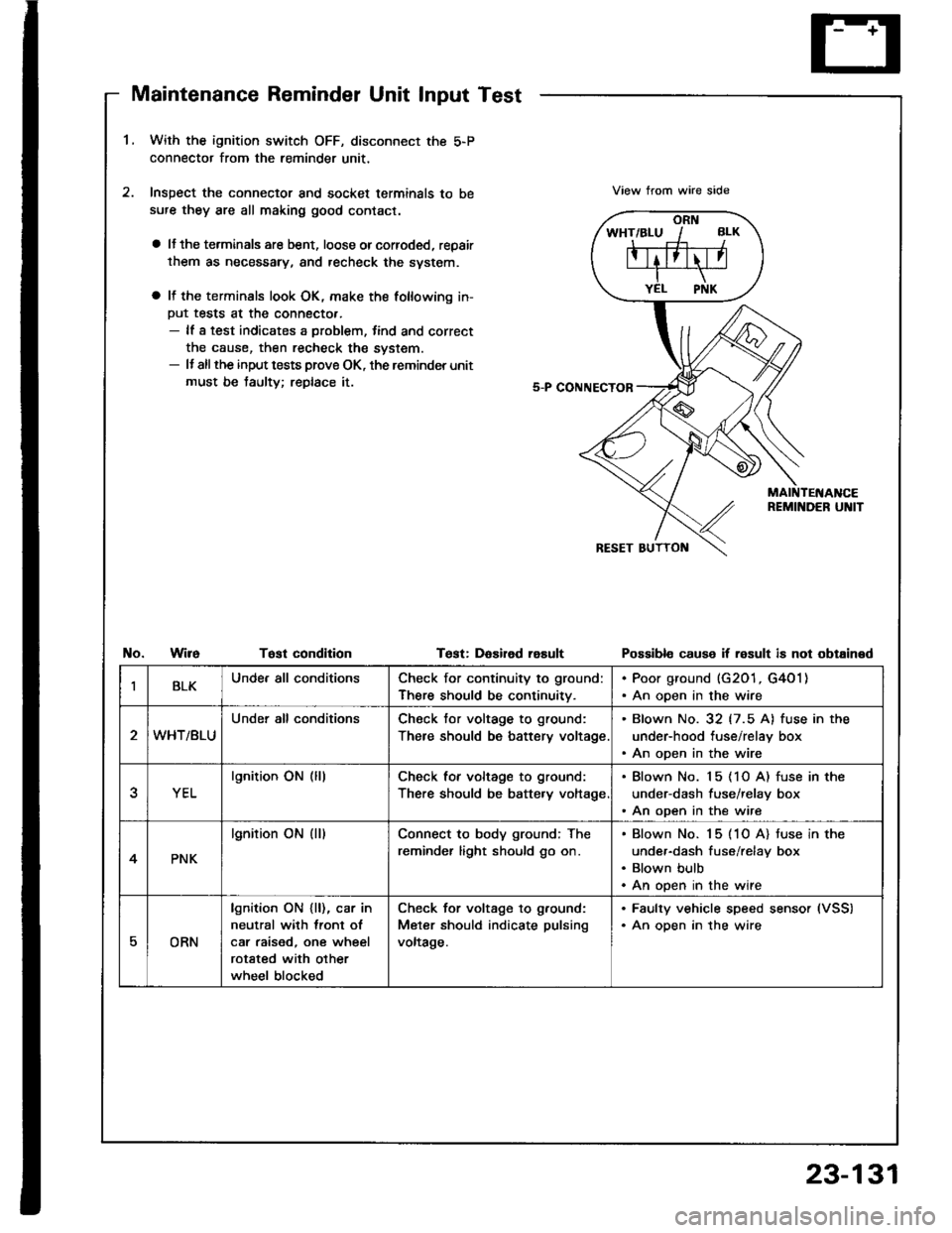
1.With the ignition switch OFF, disconnect the 5-P
connector from the reminder unit,
Inspect the connector and socket terminals to be
sufe they are all making good contact.
a lJ the terminals are bent, loose orcorroded, repair
them as necessary, and recheck the svstem.
a It the terminals look OK, make the following in-
Put tests at the connecto..- lf a test indicates a problem, tind and correct
the cause, then recheck the system.- It allthe input tests prove OK, the reminder unit
must be taulty; replace it.
View trom wire side
No.WireTost condltionTest: DaEired rasultPossibl€ cause if result is not obtained
IBLKUnde. all conditionsCheck for continuity to ground:
There should be continuitv.
. Poor ground (G201, G4O1). An open in the wire
WHT/BLU
Under all conditionsCheck tor voltage to ground:
There should be battery voltage
. Blown No. 32 (7.5 A) fuse in the
under-hood tuse/relay box. An open in the wire
YEL
lgnition ON (lllCheck for voltage to ground:
There should be batte.y voltage
. Blown No. 15 (1O A) fuse in the
under-dash fuse/relay box. An open in the wire
4PNK
lgnition ON (ll)Connect to body ground; The
reminder light should go on.
Blown No. 15 (1O A) tuse in the
under-dash fuse/relay box
Blown bulb
An open in the wire
EORN
lgnition ON {ll), car in
neutral with lront ol
car raised, one wheel
rotated with other
wheel blocked
Check for voltage to g.ound:
Meter should indicate pulsing
voltage.
. Faulty vehicle speed sensor (VSS)
. An oDen in the wire
23-131
Page 1292 of 1413
Side Marker/Turn Signal/Hazard Flasher System
Turn Signal/Hazard Relay Input Test
CAUTION:
a All SRS electrical wiring harn6ss6s ar€ covered with
yellow insulation.
a B€foro disconn6cting any part of th€ SRS wire har-
noss, connoct tho short connector(s).
a Replaco tho ontiro sftoctod SRS harness ass€mbly it
it has an open circuit or damagod wiring,
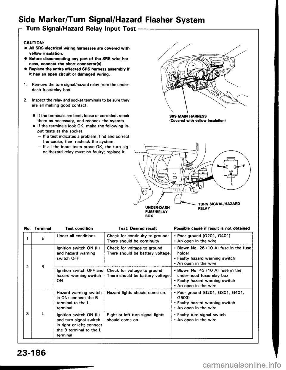
I . Remove the turn signal/hazard relay from ths under-
dash Juse/relay box.
2. Inspect the relay and socket terminals to be sure they
are all making good contact.
a It the terminals are bent, loose or coroded, repair
them as necessary, and recheck the system.
a lf the terminals look OK, make the tollowing in-
put tests at the socket.- lf a test indicates a problem, find and correct
the cause, then recheck the system.- lf all the input tests prove OK, the turn sig-
nal/hazard relay must be taulty; replace it.
UI{DEB-DASHFUSE/RELAYBOX
Test: D€sired rosult
SBS MAIN HAR ESS{Covg.ed with yollow inrulltion)
TelminalTeEt conditionPo$iblo causo it fosult is not obtainod
,lEUnder all conditionsCheck for continuity to ground:
There should be continuitv.
. Poor ground (G201 , G4O1). An oDen in the wire
2B
lgnition switch ON (ll)
and hazard warning
switch OFF
Check for voltage to ground:
There should be battery voltage.
Blown No. 26 (10 A) fuse in ths fuse
holder
Faulty hazard warning switch
An open in the wire
lgnition switch OFF and
hazard warning switch
ON
Check for voltage to ground:
There should be battery voltage.
Blown No. 43 (10 Al fuse in the
under-hood fuse/relay box
Faulty hazard warning switch
An ooen in the wire
3
Hazard wa.ning switch
is ON; connect the B
terminal to the L
termrnat.
Hazard lights should come on.Poor ground (G2O1, G3O1, G4O1
G503)
Faulty hazard warning switch
An open in the wire
lgnition switch ON (lll
and turn signal switch
in right or left; connect
the B terminal to the L
terminal.
Right or left turn signal lights
should come on.
. Faulty turn signal switch. An open in the wire
23-186
-
Page 1321 of 1413
Switch Test
1, Remove the dashboard lower cover.
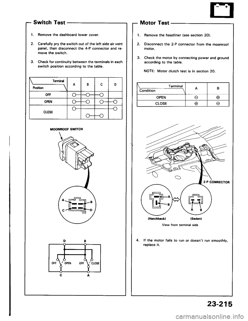
2. Carefully pry the switch out of the left side air vent
Danel, then disconnect the 4-P connector and re-
move the switch.
3. Check lor continuity between the terminals in each
switch position sccording to the table,
MOONROOF SWITCH
Motor Test
Remove the headliner (see section 20).
Disconnect the 2-P connector from the moonroot
moror.
Check the motor by connecting power and ground
according to the table.
NOTE: Motor clutch test is in section 20.
lHatchblckl (Scd!n)
View from terminal side
It the motor fails to run or doesn't run smoothly.
replace it.
4.
Torminal
P"ri i-
---__\AID
OFFG---o
OP€No---oG-
CLOSE
o---o
Te.minal
Condition -- ---------lAB
OPENo
CLOSE@
,l
rd\./ cLos€
Y
IOPEiIIOFF
23-215
Page 1334 of 1413
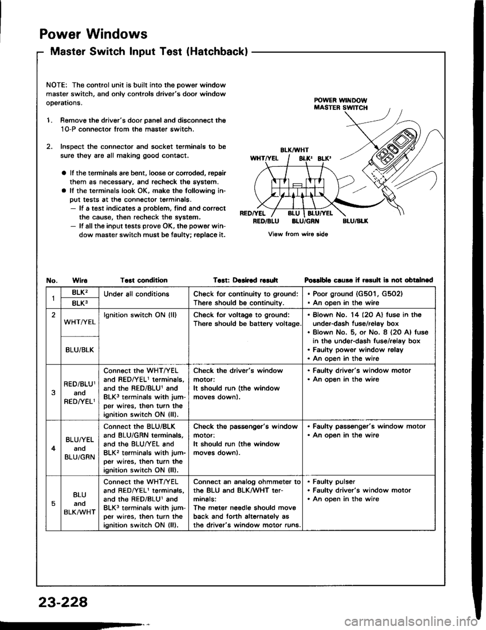
Power
Master
Windows
Switch lnput Test(Hatchback)
NOTE: The control unit is built into the power window
master switch, and onlv controls driver's door window
operations,
1. Remove the driver's door panal and disconnect the
1O-P connectol from the master switch.
2. lnsDect the connector and socket terminals to be
sure they are all making good contact.
a lf the terminsls arc bent, loose or corroded, rspair
them as necessary, and recheck the system.
a lf the terminals look OK, make the following in-
put tests at the connector terminals.- lf a test indicates a problem, find and correct
the cause, then recheck the systsm.- lf all the input tests prove OK, the powsr win-
dow master switch must be faulty; replace it.
RED/YEL
RED/BLUBLU/GR'{BLU/BLK
View from wirs sido
WiroTost conditionTost: Dashod r€suhPGslblo cluso if rosuh ir not obtalnad
1BLK'Under all conditionsCh€ck for continuity to ground:
There should be continuity.
Poor ground (G501, G5O2)
An oDen in the wire8LK3
WHT/YELlgnition switch ON {ll)Ch6ck for voltags to ground:
Th€re should be battery voltage.
Blown No. 14 l2O Al fuse in the
under-dash fuso/relay box
Blown No. 5, or No. 8 (2O A) tuse
in the under-dash luse/relay box
Faulty power window relay
An oDen in the wire
BLU/BLK
RED/BLU1
ano
RED/YELI
Connect the WHT/YEL
and REDfYELI terminals,
and the RED/BLU1 and
BLK3 terminals with jum-
per wires, then turn the
ignition switch ON {ll).
Check the driver's window
motor:
It should run (the window
moves down).
. Faulty driver's window motor. An ooen in th€ wire
4
BLU/YEL
and
BLU/GRN
Connect the BLU/BLK
and BLU/GRN terminals,
and the BLUTYEL and
BLK2 terminals with jum-
per wires, then turn the
ignition switch ON {ll).
Check ths passengor's window
motor:
It should run (the window
moves down).
. Faulty pass€nger's window motor. An oD€n in the wire
5
BLU
anq
BLKMHT
connect the WHTTYEL
and BEDrYELI terminals,
and the RED/BLU1 and
BLK3 terminals with jum-
pe. wires, then turn the
ignition switch ON (ll).
Conn€ct an analog ohmmeter to
thE BLU ANd BLKMHT t€Tr
minals:
The meter needle should move
back and torth alternately as
th€ driver's window motor runs.
Faulty pulser
Faultv driver's window motor
An oDen in the wire
23-228
Page 1381 of 1413
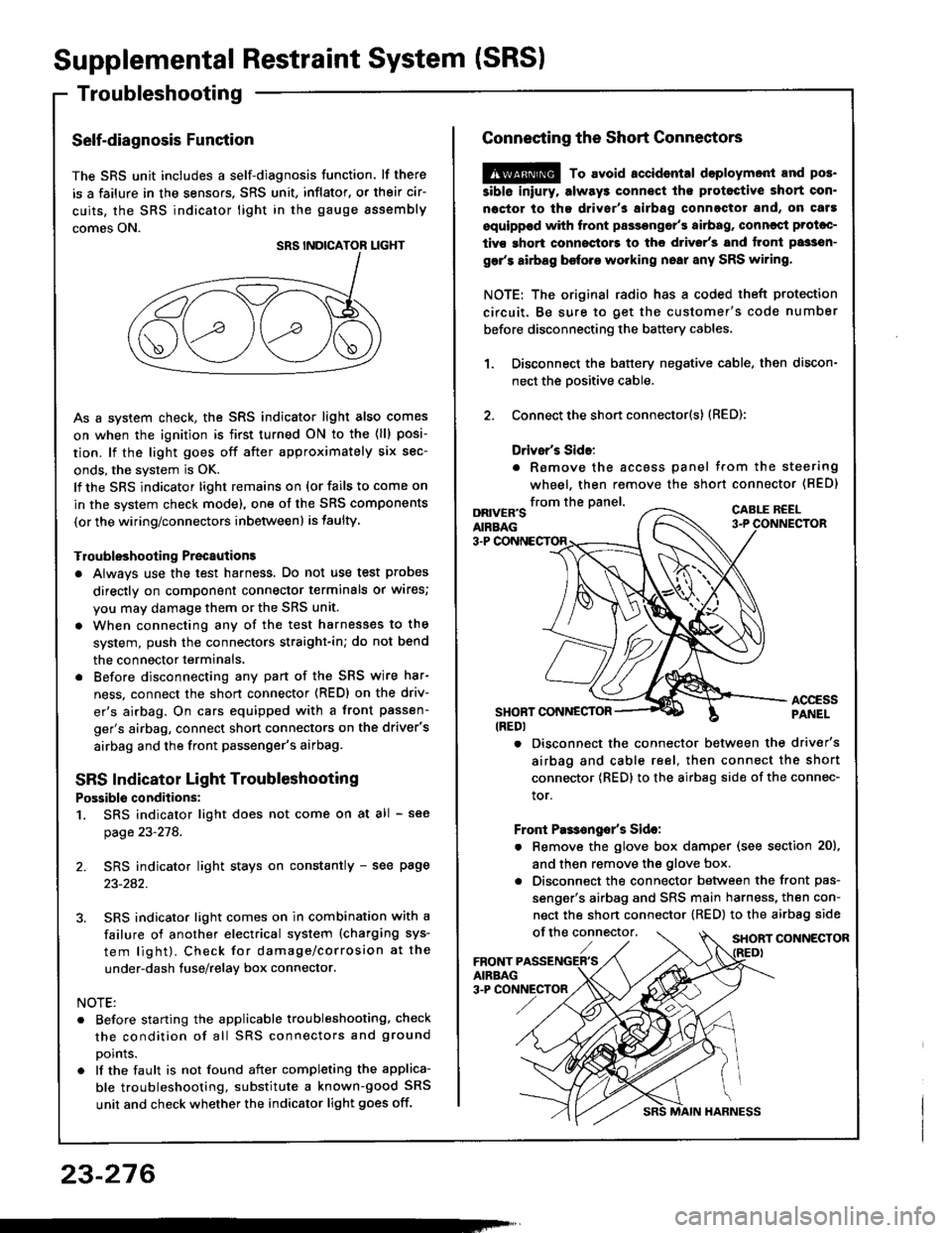
Supplemental Restraint System (SRSI
Troubleshooting
Self-diagnosis Function
The SRS unit includes a self-diagnosis function. lf there
is a failure in the sensors. SRS unit, inflator, or their cir-
cuits, the SRS indicator light in the gauge sssembly
comes ON.
As a system check, the SRS indicator light also comes
on when the ignition is first turned ON to the (ll) posi-
tion. lf the light goes off after approximately six sec-
onds, the system is OK.
lf the SRS indicator lighr remains on (or fails to come on
in the system check mode), one of the SRS components
(or the wiring/connectors inbetween) is laulty
Troubleshooting Precautions
a Always use the test harness. Do not use test probes
directly on component connector terminals or wires;
you may damage them or the SRS unit.
a When connecting any of the test harnesses to the
system, push the connectors straight-in; do not bend
the connector terminals,
. Before disconnecting any part of the SRS wire har-
ness, connect the shon connector (RED) on the driv-
er's airbag. On cars equipped with a front passen-
ger's airbag, connect short connectors on the driver's
airbag and the front passenger's airbag.
SRS Indicator Light Troubleshooting
Possiblo conditions:
1. SRS indicator light does not come on at all - see
page 23-278.
2. SRS indicator light stays on constantly - see page
23-242.
3. SRS indicator light comes on in combination with a
failure of another electrical system (charging sys-
tem light). Check for damage/corrosion at the
under-dash tuse/relay box connector.
NOTE:
. Before starting the applicable troubleshooting. check
the condition of all SRS connectors and ground
points.
. lf the fault is not found after completing the applica-
ble troubleshooting, substitute a known-good SRS
unit and check whether the indicator light goes off.
23-276
MAIN HARNESS
Connecting the Short Connectors
@ To avoid.ccidental doploymont and pos.
siblo iniury. alway3 connect ths protoctive short con.
noctor to tha driver's airbag connectot and, on caf!
equippod with front passongor's airbag, conncqt Prolac-
tivs ghort connoctors to the d.ivsr's and tront passsn-
gar's airbag before working nsai any SRS wiring.
NOTE: The original radio has a coded theft protection
circuit. Be sure to get the customer's code number
before disconnecting the battery cables,
Disconnect the battery negative cable, then discon-
nect the oositive cable.
Connect the short connector(s) (RED):
Drivsr's Sido:
. Romove the accoss panel trom the steering
wheel, then remove the shon connector (BED)
1.
2.
from the panel.DRIVER'SAIRBAG
CABLE R€EL
3-P
ACCESSPANELSHONT CONNESTOR(REDI
. Disconnect the connector between the driver's
airbag and cable reel, then connect the short
connector {RED} to the airbag side of the connec-
tor.
Front Pas€ngo/s Sido:
. Remove the glove box damper (see section 20),
and then remove the glove box.
. Disconnect the connector between the front pas-
senger's airbag and SRS main harness, then con-
nect the short connector (RED) to the airbag side
of the connector,SHORT CONNECTOR
Page 1388 of 1413
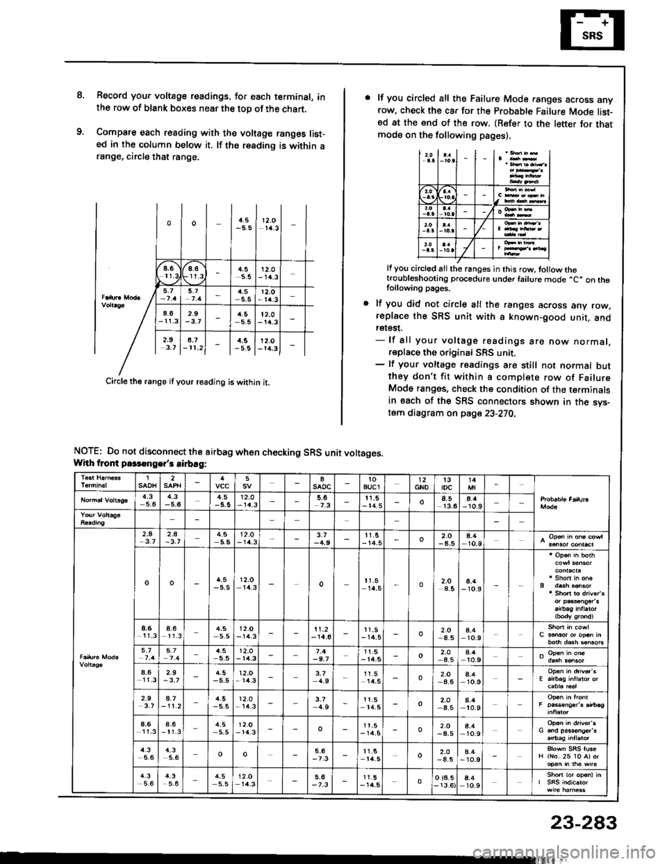
8.Record you. voltage readings. for each terminal, inthe row of blank boxes near the top of the chart.
Compare each reading with the voltage ranges list-ed in the column below it. lf ths reading is within arange, circle that range.
oo4.512,O1/4.3
".)6r-
at'9
t.g4.55.512.O- 14.3
5.t4,5r2,o-t4.3
4.62.9rl.5-5.512.0- 14.3
2.9 18.7 | l..s lr2.ol3.7 l-rr.2l - | -5.8 l-ra.3l -
Circle the range if your reading is within it.
NOTE: Do not disconnect the airbag when checking SRS unit voltages.Whh tront passongor's sirbag:
lf you circled all the Failure Mode ranges across anyrow. check the car for the Probable Failure Mode list-sd at the end of the row. (Refer to the letter for thatmode on the following pages),
I
/
It you circl€d all the ranges in this row, tollow thetroubleshooting procedure under failure mode ,,C" on thefollowing pages.
lf you did not circle all the ranges across any row,replace the SRS unit with 8 known-good unit, andretest.- lf all your voltage readings are now normal,replace the original SRS unit.- lf your voltage readings are still not normal butthey don't fit within a complete row of FailureMode ranges, check the condition of the terminalsin esch of the SRS connectors shown in the svs-tom diagram on page 23-270,
1SAOH25aSADC10auclGNOt3tDc4,35.44.3-5.64.512.0-14.3t1,5- 14.5o13.64.4- 10.9
2.5-3.72_A4.512.O- 1rt.33.1-4,911.5- r4.5o2.O-4,54.410.9
oo4.5-5,512.014_3o11.514.5o2.O4.58.4- 10.9
8,6l1_3a_6-11.34,55.512.0- 14.311.2-14.611.5- 14.5o2.O4.54.410.9
5_74.512.0- 14.3-9.7r1,5-14,5o2.O4.58.4to.9
4.62.9-3,74.5-5.512,O-14.33,74.9I1.5l4_502.O4.58.410.9
2.94.7- 11 .24.5-5.5'12.o-14.33.74.911.5- 14.5o2.Oa_54.410.9
4,6l1_3a_6-t1.34.55.512.O-14.3oI t.5- r4.5o2.O-4,54.410.9
4.3-5,64.35.6oo11.5- t lt.5o2.O-4.54.4- 1o.9
4.35,64_35.64.55.512.Or4.3-7.31 1.5- 14.5oo 18.5- 13.64.410.9
23-283