Page 285 of 1413
ldle Control System
ldle Speed Setting (cont'd)
10.
9. ldle the engine for one minute with headlights {Low}
ON and check the idle sDeed.
ldla sp6od should bo;
81881 engine:
M/T750 i 50 rpm
An75O t 50 rpm
{in $ or p] positionl
818C1 engine: 75O 1 50 rpm
Turn the headlights off.
ldle the engine for one minute with heater tan switch
at Hl and air conditioner on, then check the idle
speeo.
ldls spood should bo;
81881 ongino:
M/T82O 1 50 rpm
AN840 1 50 rpm(in [N] or lll position)
818C1 engino: 85O t 50 nm
NOTE: lf the idle speed is not within specitication,
see System Troubleshooting Guide on page 1 1-78.
11-96
Page 306 of 1413
Air Cleaner IACL)
ACL Element Rsplacoment
ACL HOUSINGCOVER
ACL ELEMENTClean air cleaner element everv15,OOO miles (24,OOO km) or 'l2 mon-ths and reDlace everv 3O,OOO miles(48,00O km) or 24 months under dus-ty conditions, rough or muddy roads.
AKE AIR OUCT
11-117
Page 319 of 1413

Emission Control System
SystemDescription
The emission control system includes a Three Way Cata-
lytic Convener (TWC), Positive Crankcase Ventilation(PCV) system and Evaporstive Emission {EVAP) Contfol
syst€m. The emission control system is designed to meet
federsl and stats emission standards.
Tailpipe Emission
Inspection
f!fifil oo nor amoro ou]rng rnr! Foacqurr. ^!op
any open flame away from yout wotk atca.
Start the engine. Hold the engine at 3,OOO rpm with
no load (A/T in @ or@ position, M/T in neutral) until
the radiator fan comes on, then let it idle,
Connect a tachometer.
Check and adiust the idle speed, if necessary (sss
page 1 1-95).
Warm up and calibrate the CO meter according to
the meter manutacturer's inst.uctions.
Check idle CO with the headlights, hester blower,
rear window defogger, cooling fan, and air condition-
er otf.
NOTE: (Canada) Pull the parking br8ke lever up.
Stan the engine, then check that the headlights are
off.
CO meter should indicate 0.1 maximum.
11-130
Page 506 of 1413

NOTE:
a Clean all parts thoroughly in solvent or carbuetor
cleaner and dry with compressed air.a Blow out all passages.
a When removing the valve body replace the following:. O-rings. Lock wsshers
1 . Remove the oil feed pipes from the servo body, s€r-
vo detent base, accumulatof cover, lock-uD valve
body and main valve body.
2, Remove the three bolts securing the ATF strainer and
servo detent base, then remove them.
3. Remove the three bolts securing the accumulator
cover. then remove the accumulator cover.
4. Remove the six bolts secu.ing the servo body, then
remove the servo body and separator plate.
5. Remove the bolt securing the secondary valve body,
then remove the secondary valve body and separa-
tor plate.
6. Remove the eight bolts securing the lubricator plate
and lock-up valve body, then remove the lubricatorplate, lock-up valve body and separator plate.
7. Femove the bolt securing the.egulator valve body,
then.emove the regulator valve body.
8. Remove the stator shaft and stopper shaft.
9. Remove the detent spring t,om the detent arm. thenremove the control shaft from the torque convenerhousing.
1O. Remove the detent arm and detent afm shaft t.om
the main valve bodv.
1 1 . Remove the four bolts secu.ing the main valve body,then remove the main valve body.
12. Remove the oil pump driven gear shaft, then remove
the oil pump gears.
'13. Remove the main separator plate with two dowelDtns.
14, Remove and clean the ATF magnet.
15.Clean the inlet opsning of the ATF strainer thorough-
ly with compressed air, then check that it is in good
condition, and the inlet opening is not clogged.
II{LET OPENING
Replace the ATF strainer it it is clogged or damaged.
NOTE: The ATF strainer can be reused if it is notclo9ged.
16.
14-115
Page 629 of 1413

lnspection and Adjustment
Pump Pressure Check
Check the fluid pressure as follows to determine
whether the trouble is in the pump or gearbox.
NOTE: First check the power steering fluid level and
pump belt tension,
CAUnON: Dilconn€st the high pros3uro ho3s with cale
!o e3 not to spill tho powor stooring fluid on th6 lramo
lnd olhor parG.
1. Disconnect the outlet hose from the oumo outlet fit-
ting, 8nd install the pump joint adapter on the
pump outlet.
2, Connect the hose joint sdapter to the power steer-
ing pressure gauge, then connect the outlet hose to
the adaotor.
3. Instsll the power steering pressure gauge to the
pump joint adaptor as shown.
OUTLET HOSE FlTnNG
HOSE ATTACHING BOLT1l Nm11.1 kg{ m 8lbf.ftl
6 x 1.0 m.n BOLT{P!rt of tooll11 N.m11.1 kgtm,8lbf.ftl
P/S JOINT ADAPTOR IPUMPIo?NAK - SmolrA
PUMP OUTI.TTFITIING
Open the shut-off valve fully.
Open the pressure control valve fully.
17 -22
1.
Start the engine and let it idle.
Turn the stee.ing wheel from lock-to-lock several
times to warm the fluid to operating temperature.
Measure steady-state fluid pressure while idling
with the shut-off valve fully open. lf the pump is in
good condition, the gauge should read less than
1500 kpa (15 kgf/cm,,213 psi).
lf it reads high, check the feed line or valve body
unit (see General Troubleshooting l7-10).
Close the shut-off valve. then close the pressure
control valve gradually until the pressure gauge
needle is stabl6, Read the pressure.
lmmediately open the shut-off valve fully.
CAUTION: Do not keep the shut-ott valvs closod
moro thgn 5 soconds or th9 pump could b6 dam"
agod by over-h6ating,
lf the pump is in good condition, the gauge should
read at least 6.400 - 7,400 kpa (65 - 75 kgIlcm,,924- 1,067 psi). A low reading means pump output is
too low for full assist. Repair or replace the pump.
10.
P/S PRESSURE GAUGE
Page 1037 of 1413

Heater and Air Conditioning
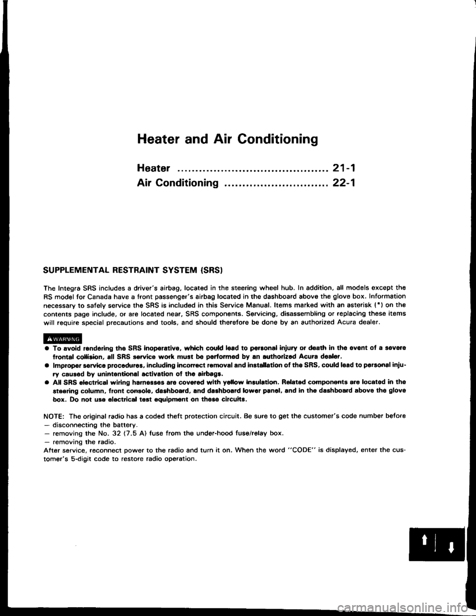
Heater ........ 21-1
Air Conditioning .......... ..22-1
SUPPLEMENTAL RESTRAINT SYSTEM {SRS}
The Integra SRS includes a driver's airbag, located in the steering wheel hub. In addition. all models except the
RS model for Canada have a front passenge.'s airbag located in the dashboard above the glovs box. Information
necessary to safely service the SRS is included in this Service Manual. ltems msrk€d with an asterisk (') on the
conlents page include, or are located near, SRS components. Servicing, disassembling or,eplacing thes€ items
will require special precautions and tools, and should therefore be done by an authorized Acura dealer.
a To avoid r6nd6dng tho SRS inoporativo. which could lead to personal injury or dealh in tho svont ot a sevele
frontal collision, all SRS servica work musl b€ portormed by an authorized Acura dealer.
a lmpropor sorvico procaduro3, including incorrect romoval and installatlon of tho SRS, could load to porsonal iniu-
ry causod by uninlonlional activation of tho ailbag8.
a All SRS eloctdcal widng harnossos are covored with yollow in3ulation. Relatsd compononts a.o locatod in tha
stsering column, flont console, daehboard, and dashboafd low6r pan6l, and in lhe dsshboa.d above lh€ glove
box. Do not uao electdcal tost equipmont on theae circuhs.
NOTE: The original radio has a coded theft protection circuit. Be sure to get the customer's code number beto.e
- disconnecting the battery.- removing the No. 32 (7.5 A) luse from the under-hood fuse/relay box.- removing the radio.
After service, reconnect power to the radio and turn it on. When the word "CODE" is displayed, enter the cus-
tomer's 5-digit code to restore radio operation.
Page 1045 of 1413

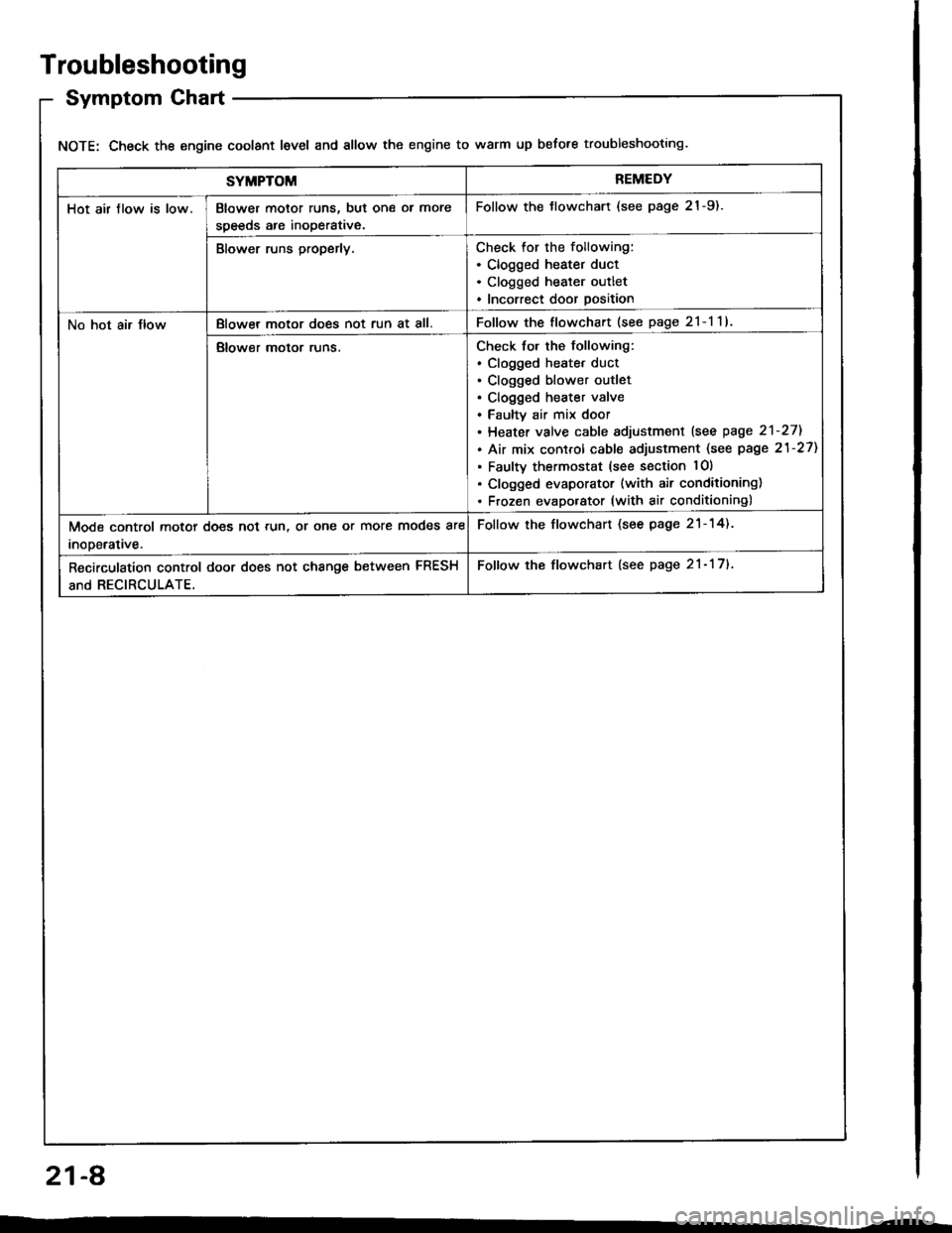
Troubleshooting
Symptom Chart
NOTE: Check the engine coolant level and allow the engine to warm up before troubleshooting.
SYMPTOMREMEDY
Hot air flow is low.Blower motor runs, but one ol more
speeds are inoperative.
Follow the tlowchart (see page 21-9).
Blower runs properly.Check for the following:. Clogged heater duct. Clogged heater outlet. Incorrect door position
No hot air JlowBlowel motor does not run at all.Follow the flowchart (see page 2l-l1l
Blower motor runs.Check for the following:. clogged heatet duct. Clogged blower outlet. Clogged heater valve. Faultv air mix door. Heater valve cable sdjustment lsee page 2'l-271
. Air mix control cable adjustment (see page 21-27)
. Faulty thermostat (see section lO)
. Clogged evaporator (with air conditioning). Frozen evaporator (with air conditioning)
Mode control motor does not run, or one or more modes are
inooerative.
Follow the flowchart (see page 21-14).
Recirculation control door does not change between FRESH
and RECIRCULATE.
Follow the flowchart (see page 21- 17).
21-A
Page 1057 of 1413

Blower Unit
Replacement
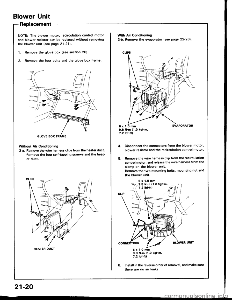
NOTE: The blower motor, recirculation control motor
and blower resistor can be replaced without lemoving
the blower unit (see page 2l-21).
1. Remove the glove box (see section 2O),
2. Remove the fou. bolts and the glove box frame.
Without Ail Conditioning
3-a. Remove the wire harness clips trom the heat€r duct.
Remove the Jour self-tapping screws 8nd the heat-
er duct.
GLOVE BOX FRAME
HEATER DUCT
With Air Conditioning
3-b. Remove the evaporator (see page 22-261.
CLIPS
6x I9.8 .ft 11.O kgt.m,7.2 tbt.ftl
4.
6.
Oisconnect the connectors from the blower motor,
blower resistor and the recirculation control motor.
Remove the wire harness clip from the recirculation
control motor, and release the wire harness from the
clamo on the blower unit.
Remove the two mounting bolts, mounting nut and
the blower unit,
6 x 1.0 mm
6 x 1.O mm9.8 N'm (1.0 kgf'm.7.2 tbt.ftl
lnstall in the reverse order of removal, and make sure
there are no air leaks.
9.8 .m (1.O kgl'm,7.2 lbf'ft}
21-20
--