1994 HONDA INTEGRA parking brake
[x] Cancel search: parking brakePage 1126 of 1413
Connector ldentification and Wire Harness Routing
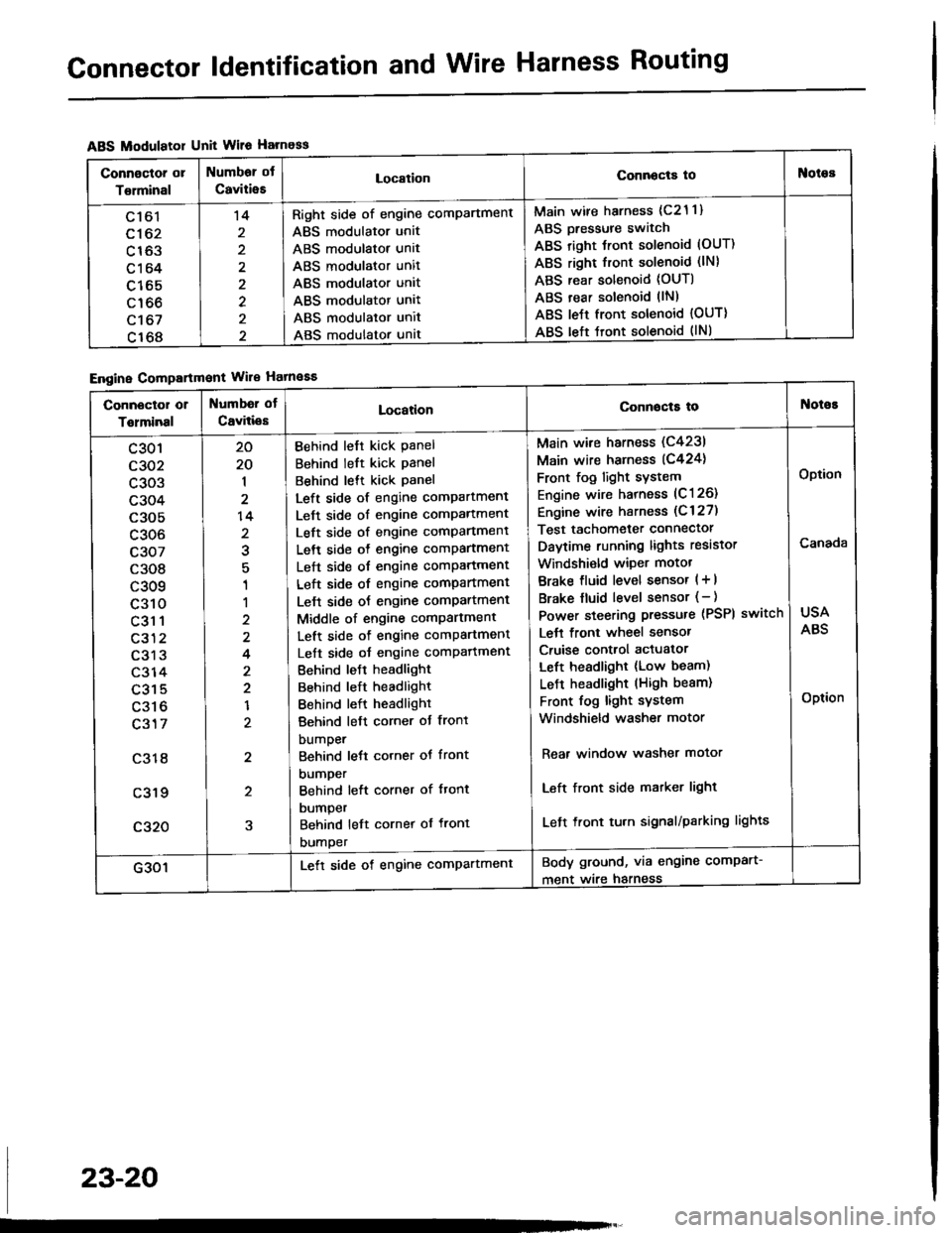
ABS Modulatol Unit Wile Harness
Engine Compartmont Wile Hatnaaa
Connoctor or
Torminal
Numbor ot
CaviiieELocationConnocta tooies
Ltol
c162
c163
c164
c165
c166
c't 67
c168
't4
2
2
Right side of engine comPartment
ABS modulator unit
ABS modulator unit
ABS modulator unit
ABS modulator unit
ABS modulator unit
ABS modulator unit
ABS modulator unat
Main wire harness (c21 1)
ABS Dressure switch
ABS right Jront solenoid (OUT)
ABS right front solenoid (lN)
ABS rear solenoid (OUT)
ABS rear solenoid llN)
ABS le{t front solenoid {OUT)
ABS left tront solenoid (lNl
Connector or
Tolminal
Numbd of
CaviliesLocationConnocta tot{oioE
c301
c302
c303
c304
c305
c306
c307
c308
c309
c310
c31 1
c312
c313
c314
c315
c316
c317
c318
c319
c320
20
20
1
2
14
2
1
1
2
4
2
2
1
2
2
5
Behind left kick Panel
Behind left kick panel
Behind lett kick Panel
Left side of engine compartment
Left side of engine comPartment
Left side of engine comPartment
Left side o{ engine comPartment
Left side of engine comPartment
Left side of engine compartment
Lelt side oJ engine comPartment
Middle of engine comPartment
Left side of engine comPartment
Left side oJ engine comPafiment
Behind leJt headlight
Behind left headlight
Behind left headlight
Behind left corner ot front
bumper
Behind lett corner ot front
DUmper
Behind left corner of ftont
DUmper
Behind left cornet of front
DUmper
Main wire harness (C4231
Main wire harness (C424)
Front fog light sYstem
Engine wire harness (C126)
Engine wire harness (C 127)
Test tachometer connector
Daytime running lights resistor
Windshi€ld wiper motot
Brake fluid level sensor ( + |
Brake fluid level sensor (- )
Power steering pressure (PSPI
Lett front wheel sensor
Cruise control actuator
Left headlight (Low beam)
LeJ-t headlight (High beam)
Front fog light system
Windshield washer motor
switch
Rear window washer motor
Left front side matker light
Left front tu.n signal/parking lights
USA
ABS
Option
Canada
Option
G301Lett side of engine comPartmentBody ground, via engine comPart-
ment wire harness
23-20
Page 1136 of 1413
Connector ldentification and Wire Harness Routing
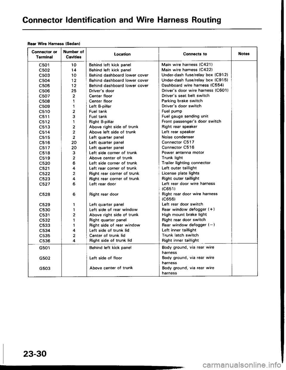
Rear Wire HamsEs (S6danl
Connector ol
Torminal
Number ot
Caviti6sLocaiionConnocts toNotos
c501
c503
c504
c505
c506
c507
c508
c509
c510aEt t
c512
L9 IJ
c514
c515
c516
c517
c518
c519
c520
c521
c522
c523
c527
c52A
LCZY
c530
c531
c532
c533
c534
c535
c536
6
1,|
2
1
I
4
4
10
10
12
25
'I
1
a
1
2
2
20
20
2
6
4
4
6
Behind left kick panel
Behind left kick panel
Behind dashboard lower cover
Behind dashboard lower cover
Behind dashboard lowe, cover
Driver's door
Center floor
Center floor
Left B-pillar
Fuel tank
Fuel tank
Right B'pillar
Above right side of trunk
Above left side ot trunk
Left quarter panel
Left quarter panel
Left quarter panel
Left side corner of trunk
Above center of trunk
Left side corner of trunk
Left rear corner of trunk
Right rear corner of trunk
Right rear corner of trunk
Left ,ear door
Right rear door
LeJt quarter panel
LeJt side oJ rear window
Above right side of trunk
Right quarter panel
Right side of rear window
Left side ot trunk lid
Center ot trunk lid
Right side ot trunk lid
Main wire harness (C421)
Main wire harness (C422)
Under-dash tuse/relay box {C912}
Under-dash fuse/relay box (C915)
Dashboard wire harness (C554)
Driver's door wire harness (C6O l )
Driver's seat belt switch
Parking brake switch
Driver's door switch
Fuel pump
Fuel gauge sending unil
Front passenger's door switch
Right rear speaker
Left rear speaker
Noise condenser
Connector C517
Connector C516
Power antenna motor
Trunk light
Trailer lighting conneclor
Left outer taillighr
License plate lights
Right outer taillighr
Left rear door wire harness
(c651)
Right rear door wire harness
(c656)
Lett rear door switch
Rear window delogget (+ )
High mount btake light
Right rear door switch
Rear window defogger (- )
Left inner taillight
T,unk latch switch
Right inner taillight
G501
G502
G503
Behind lett kick panel
Left side of floor
Above center of trunk
Body ground, via rear wire
narness
Body ground, via rear wire
narness
Body ground, via rear wire
narness
23-30
Page 1233 of 1413
Brake System lndicator
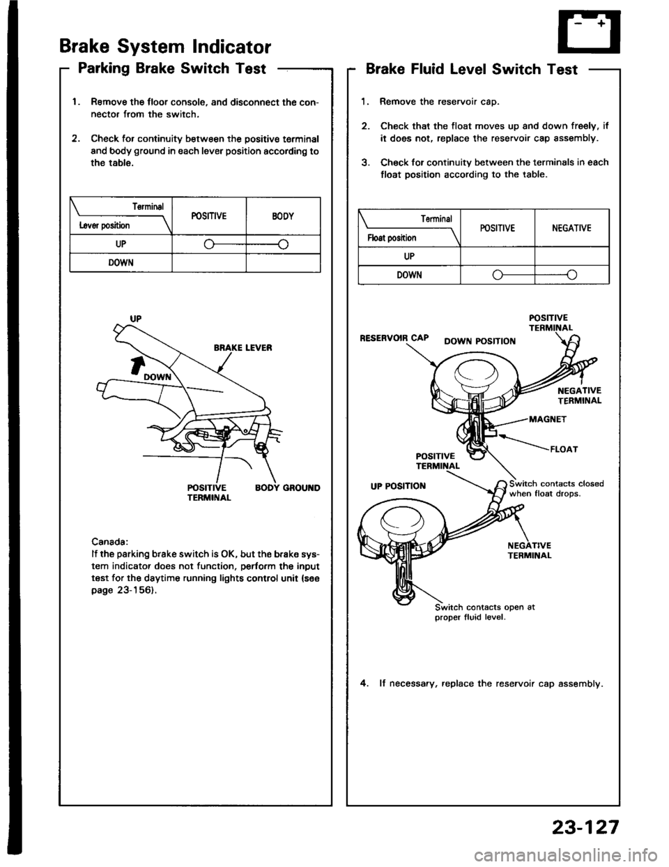
Parking Brake Switch Test
Remove the tloor console, and disconnect the con-
nector from the switch.
Check for continuity b€tween the positive terminal
and body ground in each lever position accordino to
the table.
Canada:
lf the parking brake switch is OK, but ths brake sys-
tem indicator does not function, pertorm the input
test for the daytime running lights control unit (see
page 23-156).
L6vor position
TorminalPOSITIVEEODY
UP
DOWN
Brake Fluid Level Switch Test
Remove the reservoir caD.
Check that the tloat moves up and down freely, if
it does not, replace the reservoir cap sssembly.
Chsck for continuitv between the terminals in each
float position according to the table.
RESERVOIR CAPDOWN POSITION
when float drops.
4. lf necessary, replace the reservoir cap assemblv.
Terminal
Float positionPOSITIVENEGATIVE
UP
DOWN-o
POStTtVE
TERMINAL
Switch contacts open atproper fluid level.
23-127
Page 1255 of 1413
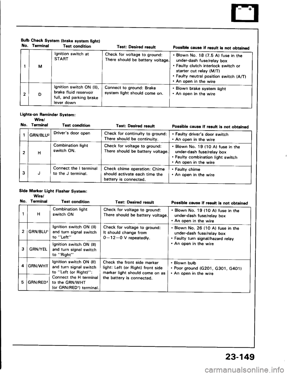
Bulb Check System
No. Tsrminal
(blake system lightl
Test condition
Lights-on Romind6r Systom:
Wire/
No, ToiminalT6Et condition
Side Markol Light Flashar System:
Wiro/
No. TerminalTest condition
Tost: Desirod resuhPossibls caus6 it result is not obtainod
Tost: Dositod rosuhPossibl6 caus6 if rosuh is not obtainod
Tast: Desired rosultPo$ible cause if result is not obtained
IM
lgnition switch at
STARTCheck lor voltage to ground:
There should be battery voltage.
Blown No. 18 {7.5 Al fuse in theunder-dash fuse/relay box
Faulty clutch int€rlock switch or
starter cut relay {M/T}Faulty neutral position switch (A/T)
An open in the wire
D
lgnition switch ON (ll),
brake fluid reservoir
tull, and parking brake
lever down
Connect to ground: Brake
system light should come on.
. Blown brake system light. An oDen in the wire
GRN/8LU'Driver's door openCheck for continuity to ground:
There should be continuity.
. Faulty driver's door switch. An oDen in the wire
H
Combination light
switch ON.
Check for voltage to g.ound:
There should be battery voltage
Blown No. l9 (1O A) tuse in the
under-dash fuse/relav box
Faulty combination light switch
An oDen in the wire
5
Connect the I terminal
to the J terminal.
Check chime operation: Chime
should activate each time the
batterv is connected,
. Faulty chime. An open in the wire
1H
Combination light
switch ON
Check for voltage to ground:
There should be battery voltage
. Blown No. 19 (1O A) tuse in the
under-dash fuse/relay box. An open in the wire
GRN/BLU1
lgnition switch ON {ll)and turn signal switch
to "Left"
Check for voltage to ground:
It should change from
O-12-O V repeatedly.
Blown No. 26 (10 A) luse in theunder-dash fuse/relav box
Faulty turn signal/hazard relay
An oDen in the wire2GRN/YEL
lgnition switch ON {ll)and turn signal switch
to "Right"
4GRN/WHTlgnition switch ON (ll)
and turn signal switch
to "Left (or Rightl":
Connect the H terminal
to the GRNMHT(or GRN/REDl) terminal.
Check the front side marker
light: Left (or Right) front sidemarker light should come on asthe batterv is connected.
Blown bulb
Poor ground (G2O1, c3O1, G4O1lAn open in the wire
GRN/REDl
23-149
Page 1261 of 1413
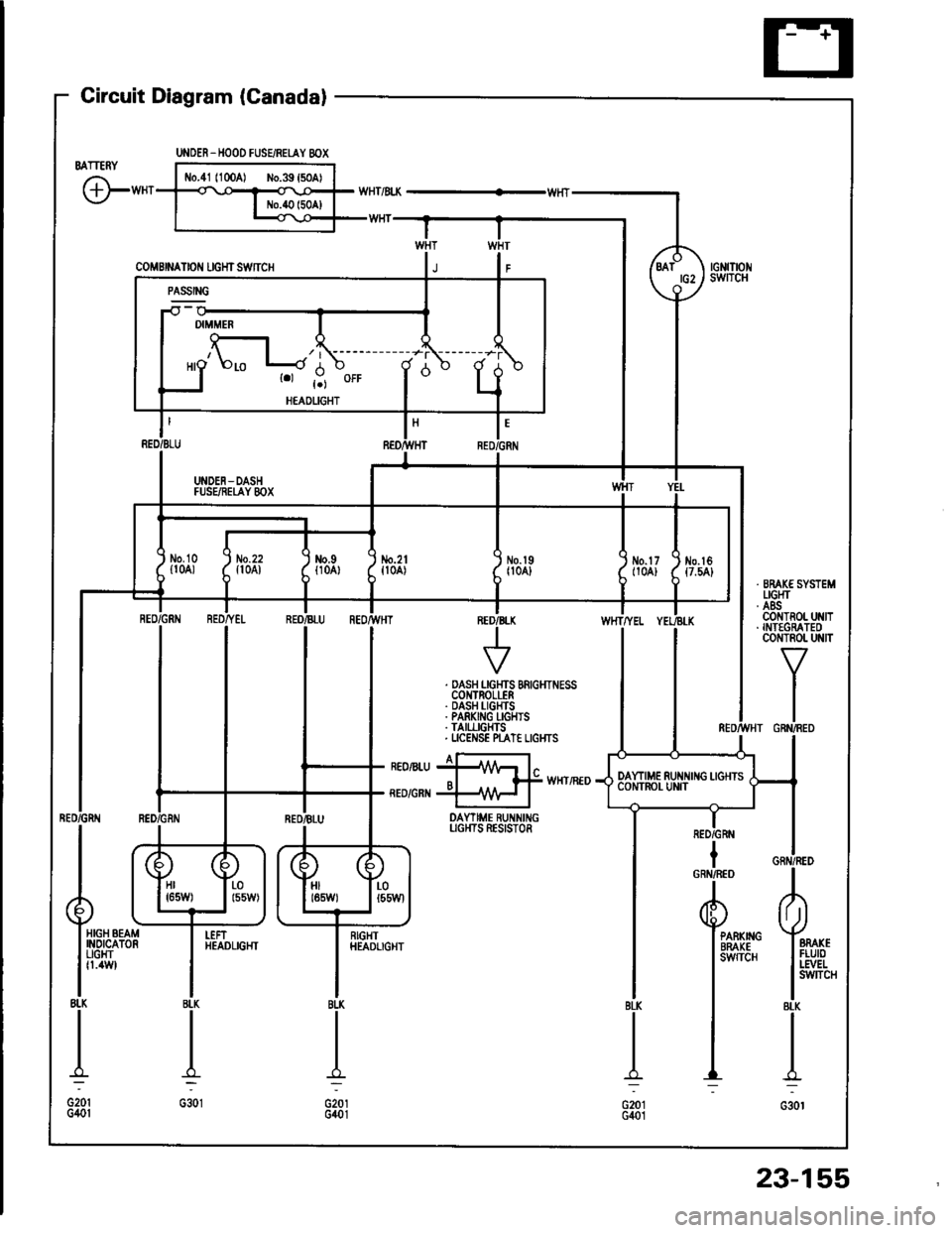
Gircuit Diagram (Canadal
BATTERY
G"*
UNOER_HOOD FUSEiRETAY 8OX
coMBrNAtor{ rcHrswnc
-il w
| '.=r" I
ll'L I I
I I *o\." l-'li' ;- ;j
I LI
"- r.r-,9 "orr
I
d "
L
RED/BLU REO/}VHT RED,ll
I UNDEN-DASH II FUSEiIEI,AY 8OX I
tl
L-J
t'GRN
/d\BATtG2\9-l
rGNrTrot{swITcH
No.2lfl0A)\I
No.l9|l04]Jm.tr (
t10A) ttt
I
No.l6{7.54}
tl
i,"#
llrrff li'rrt,
RED/GRtIIBLU REOr'TVHTINED/B
V
WHTTYEL
. DASH LGHTS BRIGHTNESSCOI{TROLLER. DASH I-IGHTS. PARKING I-GHIS. TAII,LIGHTS. UCENSE N"AT€ LIGI{TS
I a-rneonru jllA/Vr l"o I f# wxrintoRED/GRI{ +\{H I
DAYTIME RUNNINGUGI{TS RESISTOR
IRED/GRN
Hr I r-01651,1/) | l55W)HIt85W)LOt55Wl
HIGH BEAMINOICATORUGHTfl.4W
I
RIGHTHEADLIGHTPARKIIIGBRAKEsw{TcH
23-155
Page 1263 of 1413
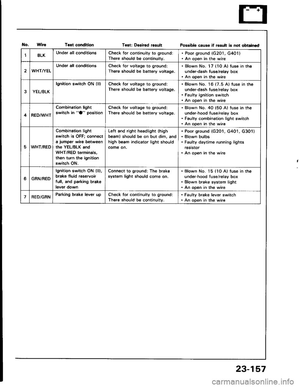
T€st conditionTest: Desirad losultPossibla cause if rosult is not obtainad
1BLKUnder all conditionsCheck for continuity to ground:
There should be continuity.
. Poor ground {G201, G401). An open in the wire
WHT/YEL
Under all conditionsCheck Jor voltage to ground:
There should be battery voltage.
. Blown No. 1 7 { 10 A} luse in the
under-dash tuse/relay box. An ooen in the wiae
YEL/BLK
lgnition switch ON (ll)Check tor voltage to ground:
There should be battery voltage.
Blown No. 16 (7.5 A) tuse in the
under-dash fuse/relay box
Faulty ignition switch
An open in the wire
4RED/WHT
Combination light
switch in "O" positionCheck for voltage to ground:
The.e should be battery voltage.
Blown No. 40 {5O A) fuse in the
under-hood fuse/relay box
Faulty combination light switch
An ooen in the wire
5WHT/REO
Combination light
switch is OFF; connect
a iumper wire between
the YEL/BLK and
WHT/RED terminals,
then turn th6 ignition
switch ON.
Left and right headlight (high
beaml should be on but dim, and
high beam indicator light should
come on.
Poor ground (G201 . G401 . G301)
Blown bulbs
Faulty daytime running lights
reststor
An open in the wire
ttGRN/RED
lgnition switch ON (ll),
brake fluid res€rvoil
full, and parking brake
lever down
Connect to ground: The brake
system light should come on.
Blown No. 15 (1O A) tuse in the
under-hood fuse/relay box
Blown brake system light
An open in the wire
RED/GRNParking brake lever upCheck for continuity to ground:
The.e should be continuitv.
. Faulty brake lever switch. An open in the wire
23-157
Page 1272 of 1413
-
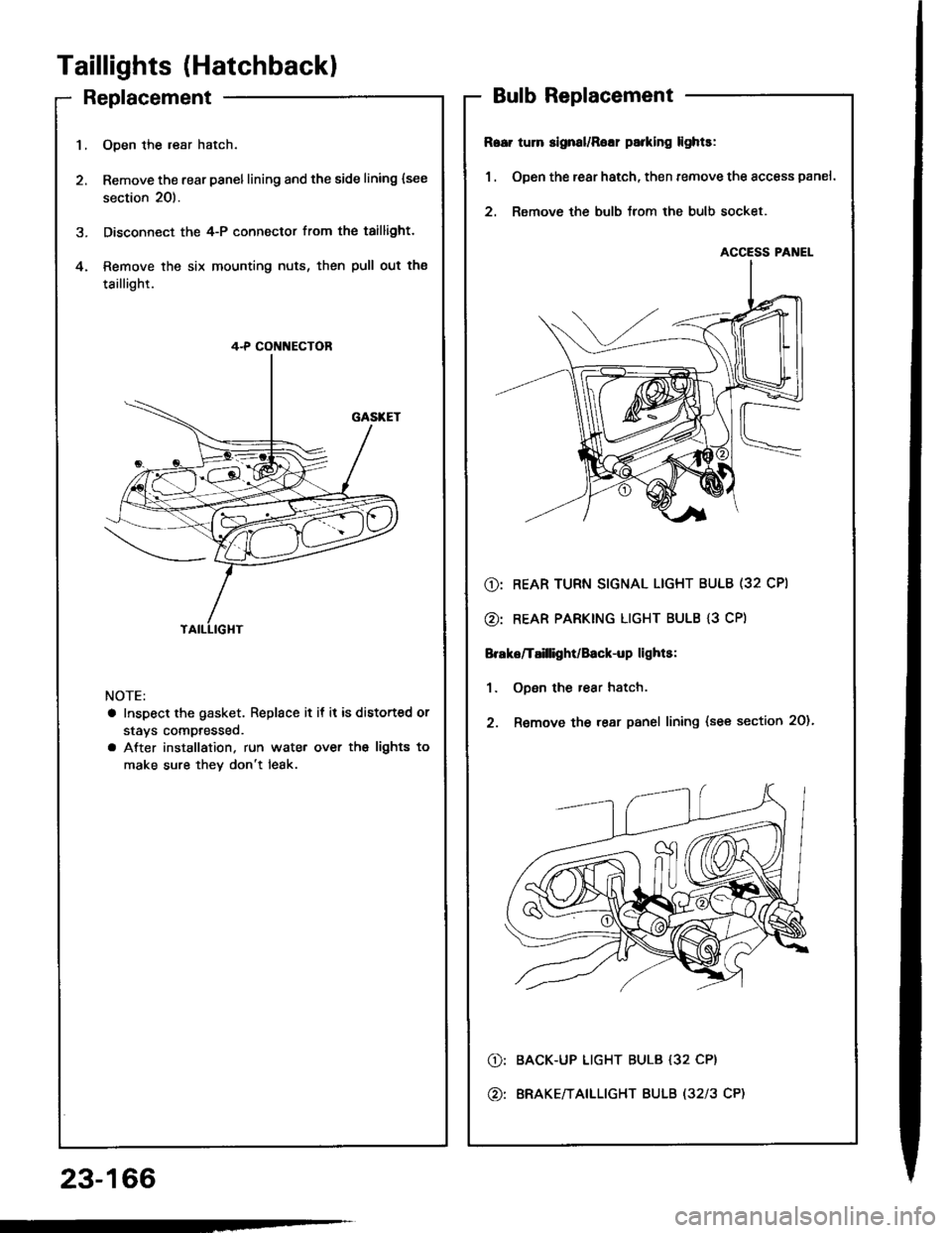
Taillights (Hatchbackl
Replacement
23-166
1.Open the resr hatch.
Remove the rear panellining and the side lining {see
section 20).
Disconnect the 4-P connector from the taillight.
Remove the six mounting nuts, then pull out the
taillight.
4.
NOTE:
a Inspect the gasket. Replace it if it is distorted or
stavs compresseo.
a After installation. run wate. over ths lights to
make sure thev don't leak.
4-P CON[{ECTOR
BulbReplacement
R6ei tum slgnal/Rolr parking lights:
1 . Open the rear hatch, then remove the access panel.
2. Remove the bulb lrom the bulb socket.
@: REAR TURN SIGNAL LIGHT BULB (32 CPI
@: REAR PARKING LIGHT BULB {3 CP)
Brake/T8illight/Back-up lights:
1. ODen the rear hatch.
2. Remove the rear panel lining {see section 20).
BACK-UP LIGHT BULB {32 CP}
ERAKE/TAILLIGHT BULB (32l3 CP)
o:
@:
ACCESS PANEL
Page 1274 of 1413
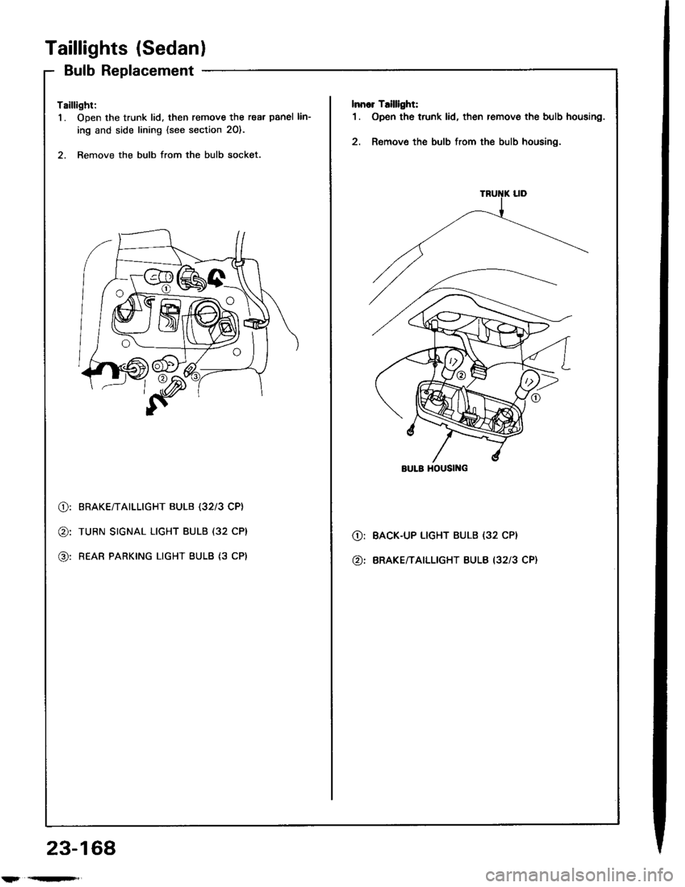
Taillights (Sedanl
Bulb Replacement
Tsillight:
1. Open the trunk lid. then remove the rear panel lin-
ing and side lining {see section 20}.
2. Remove the bulb from the bulb socket.
lnnor T.illlght:
1. Open the trunk lid, then remove the bulb housing.
2. Remove the bulb from the bulb housing.
@:
@:
@:
BRAKE/TAILLIGHT BULB (32l3 CP}
TURN SIGNAL LIGHT BULB (32 CP}
REAR PARKING LIGHT BULB {3 CP)
O:
@:
BACK-UP LIGHT BULB (32 CP}
BRAKE/TAILLIGHT BULB I3213 CP}
BULB HOUSII{G
23-168
l'r'qn'F',