1994 HONDA INTEGRA charge system
[x] Cancel search: charge systemPage 232 of 1413

PGM-FI System
System Description
ENGINE CONTROL MODULE (ECMIOUTPUTS
PGM-Fl System
The PGM-Fl system on this model is a sequential multipon fuel injection system,
Fuol Iniector Timing and Duration
The ECM contains memories tor the basic discharge durations at various engine speeds and manifold pressures. Thebasic discharge duration, after being read out from the memory, is turther modilied by signals sent from vanous sensofsto obtain the final discharge duration.
ldle Air Control
ldle Air Control Valve (lAC Vatve)
When the engine is cold, the A/C compressor is on, the transmission is in gear (A/T only) the brake pedal is depressed,the P/S load is high, or the alternalor is charging, the ECM controls current to the IAC Valve to maintain correct idle soeed.
lgnition Timing Controla The ECM contains mamories for basic ignition timing at various engine speeds and manifold pressures. lgnition timingis also adjusted for engine coolant temperature.a A Knock Control System is also used. when detonation is detected by the knock sensof. the ignition timing is retarded(B18Cl engine).
Other Control Functions
1. Starting Control
When the engine is started. the ECM provides a rich mixture by increasing fuel injector duration.2. Fuel Pump Control
a When the ignition switch is initially turned on, the ECM supplies ground to the PGM-Fl main relay that suppliescurrent to the fuel pump tor two seconds to pressurize the tuel system.a When the engine is running, the ECM supplies gfound to the PGM-Fl main relay that supplies current to the fuel pump.a When the engine is not running and the ignition is on, the ECM cuts ground to the PGM-FI main relav which cutscurrent to the fuel pump.
TDC/CKP/CYP Sensor
MAP Senso.
ECT Sensor
IAT Sensor
TP Sensor
HO2S
vss
BARO Sensor
ELD
Starter Signal
ALT FR Signal
Air Conditioning Signal
A/T Gear Position Signal
Battery Voltage {lcN. 1)
Brake Switch Signal
PSP Switch Signal
Knock Sensor'
VTEC Pressure Switchr
Fuel-lnjectors
PGM-FI Main Relay (Fuel Pump)
MIL
IAC Valve
A/C Compressor Clutch Relay
Radiator Fan Relav
Condenser Fan Relav
ALT
rcM
EVAP Purge Control Solenoid
HO2S Heater
VTEC Solenoid Valve'
IAB Control Solenoid Valve*
lFuet tnjector Timing and Duration]
I Electr..l"ldle Contr;il
Fit'e' contr; Funcrfit
l6tio; Ttntrlg c..trol
tEcM aack-,rp Functiorlsl
': 818C 1 €ngine
11-40
Page 298 of 1413

[":::,::-'
Eecause of its compact impeller design, the fuel pump is installed inside the fueltank, thereby saving space
ng the fuel line system.
FUEL PUMP
FUEL FILTER
FUEL PUMP BRACKET
FUEL PUMP CROSS SECTION lsido vi6rvl
IMPELLERS
CHECK VALVEPUMP CASING
The fuel oumo consists of a DC motor, a circumference flow pump, a relief valve for ptotecting the fuel lir
a check valve for retaining residual pressure, an inlet port, and a discharge port. The fuel pump assembly
the impellers (driven by the motor), the fuel pump casing {which forms the pumping chsmber), and the fuel p
OPERATION(1 ) When the engine is started. the PGi/t-Fl main relay actuates the fuel pump, and the motor turns togeth
impellers.
Differential pressure is generated by the numerous grooves around the impellers.
(2) Fuel entering the inlet porr flows inside the motor from the pumping chambe. and is forced through th
port via the check valve.
lf tuel flow is obstructed at the discharge side of the tuel line, the relief valve will open to bypass the
inlet port and prevent excessive fuel pressure.
(3) When the engine stops, the tuel pump stops automatically. However, a check valve closes by gravity t
residual pressure in the line, helping the engine to aestan more easily.
and simplify-
N lTop vi6w)
PORT
GROOVES
fuel line systems,
embly consists of
fuel pump cover.
together with the
rgh the discha.ge
ss the fuel to the
avitv to retain the
(cont'd)
PUMP COVER
FUEL PUMP ASSEMBLY CROSS SECTION
D|SCHARGE FORT ^ . tNLEr P
IMPELLER
11-109
Page 430 of 1413

Description
Lock-up System
Lock-up Clutch
1. Operation (clutch on)
With the lock-up clutch on, the oil in the chamber between the torque convener cover and lock-up piston is discharged,and the converter oil exerts pressure through the piston against the converter cover. As a result, the converter turbineis locked on the converter cover firmly. The etfect is to bypass the converter, thereby placing the car in direct drive.
tpowefJlo-wl
The power tlows by way of:
Engine
I
Drive plate
I
Torque convener cover
I
Lock-up piston
I
Damper spring
I
Turbine
t
Mainshaft
TOROUE CONVERTERCOVER
LOCK-UP
TURBINE
To oil cooler
2. Operation (clutch off)
With the lock-up clutch off, the oil tlows in the reverse of CLUTCH ON. As a result, the lock-up piston is moved away
from the converter cover; that is, the torque converter lock-up is released.
Fowtttowl
Engine
I
Drive plate
I
Torque converter cover
Pump
I
Turbine
I
Mainshaft
OUTLET
t
,\
TURBINE
14-38
Page 558 of 1413

Transmission
Cooler Flushing
S!@ ro prevent iniury to tace and eyes, always
wear safety glas$es or a tace shield when using the trans-
mission flusher.
NOTE: This procedure should be performed before rein-
stalling the transmission.
1. Check tool and hoses for wear or cracks before
using.
lf wear or cracks are found, replace the hoses be-
fore using.
2. Using the measuring cup, tillthe tank with 21 ounces
{approximately 213 lulll of biodegradable tlushing
fluid (J35944-20). Do not substitute with any other
fluid.
Follow rhe handling procedure on the fluid container.
Secure the tlusher filler cap and pressurize the tank
with compressed air to between 550-829 kPa(5.6-8.45 kgt/cm,, 80- 120 psi),
NOTE: The air line should be equipped with a water
trap to ensure a dry air system.
Hang the tool under the vehicle.
Attach the discharge hose of the tank to the return
line of the transmission cooler using a clamp.
Connect the drain hose to the inlet line of the trans-
mission cooler using a clamp. Securely clamp the op-posite end of the drain hose to a bucket or floor drain.
6.
DRAIN HOSE
TRANSMISSION
TRANSMISSIONCOOLER FLUSHEBCommorcially AvailabloKENT MOORE #J38405_A
DISCHARGE HOSE
14-168
BUCKET
7. With the water and air valves off. attach the water
and air supplies to the flusher. (Hot water it
available.)
OFF
8. Turn on the flusher water valve so water will tlow
through the oil cooler for 1O seconds. lf water does
not flow through the oil cooler it is completely
plugged, cannot be flushed, and must be replaced.
9. Depress the trigger to mix the tlushing lluid into the
water tlow. Use the wire clip to hold the trigger
oown.
10. While flushing with the water and flushing fluid for
2 minutes. turn the air valve on for 5 seconds every
15-20 seconds to create a surging action.
AIR PRESSURE:
MAX 829 kPa (8.45 kgt/cm,, 12O psi)
1 1. Turn the water valve off. Release the trigger, then
reverse the hoses to the cooler so you can flush in
the opposite direction. Repeat steps 8 through 1O.
12. Release the trigger and allow water only to rinse the
cooler with water for one minute.
13. Turn the water valve off and turn off the water
supply.
14. Turn the air valve on to dry the system out with air
for two full minutes or until no moisture is visible
leaving the drain hose.
CAUTION: Residual moisture in the oil cooler 01
pipes can damage the transmission.
15. Remove the flusher trom the cooler line. Attach the
drain hose 10 a oil container.
16. lnstallthe transmission and leave the drain hose at-
tached to the cooler line.
Page 613 of 1413

System Description
Steering Pump (cont'dl
Flow Control
The flow control valve in the pump performs the follow-
ing steps @ through O to control the flow of fluid, i.e. to
increase the discharge volum€ wh6n engine speed is
low and to decrease it when the engine speed increases.
The assistance thrust of the steering gearbox changes in
compliance with the change in the discharge volume.
When the engine starts, fluid discharged from the
discharge port starts to run through the metering
orifice in the pump. The discharge volume increas€s
as the engine speed increases,
As the flow has already been regulated by the
metering orifice when the engine speed is at or near
the idle speed, a constant and regulated amount ot
fluid is discharged until the engine speed reaches
the middle speed range. As the engine speed
increases, the pressure difference between the ends
of the metering orifice increases. A pressure differ-
ence is created between the top and bottom ends ofthe flow control valve, too, pushing the flow control
valve to open the by-pass passage. This allows the
excess fluid to return to the inlet pon preventing
pressure at the discharge port trom rising exces-
sively.
As the engine speed continues to increase, the tlow
control valve is pushed back further. When the
engine speed reaches a given speed. the return pas-
sage outside the metering orifice is connected to
the inlet port, and the opening to the inlet port
widens in proportion to the increase in engine
speed. This makes pan of the fluid regulated by the
metering orifice return to the inlet pon of the pump;
there by discharged fluid from the pump is
decreased slowly by this amount.
The orifice in the return passage regulates and
maintains the flow of fluid discharged from thepump at a given level until the engine speed reach-
es the high speed range.
.5IJ
lot=ro
FLOW CURVE
PUMP R.P,M.
o
@
VALVE
@
@
17-6
Page 1074 of 1413

Description
Outline
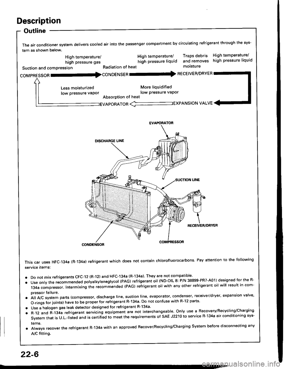
The air conditioner system delivers cooled air into the passenger compartment by circulating refrigerant through the sys-
tem as shown below.
CONDENSOR
This car uses HFC-134a {R-134a) refrigerant which does not contain chlorofluorocarbons Pay attention to the following
service items:
. Do not mix refrigerants CFC-I2 (R-l21 and HFC-134a (R-134a) They are not compatible'
. Use onty the recommended potyatkytenegtycol {PAG) refrigerant oil (ND-OIL 8: P/N 38899-PR7-A01) designed for the R-
134a compressor. Intermixing the recommended (PAG) refrigerant oil with any other refrigerant oil will result in com-
pressor tailure.
.A||lvcsystemparts(compressor.dischargeIine,suotionIine,evaporator,condenser.receiver/dryer,expansionva|ve.
o-ringsforioints}havetobeproperforre'rigerantR-l34a.DonotconfusewithR.l2parts.
. Use a halogen gas leak detector designed for refrigerant R-134a'
. R-.12 and C-l34a refrigerant servicing equipment are not interchangeable. Only use a Recovery/Recyclins/Charging
System that is U.L.-listed and is certifLd to meet the requirements of sAE J2210 to service R-134a air conditioning sys-
rems.
. Always recover the refrigerant R-134a with an approved Recover/Recycling/Charging System before disconnecting any
A,/C fitting.
coMpRESsoR -coNDENSER - RECEIVER/DRYER
High temperature/
high pressure gas
Suction and comPression
Less moisturized
low pressure vaPor
High temperature/ Traps debris High temperature/
hilh pressure liquid and removes high pressure liquid
Radiation of heat molsture
More liquidified
low Pressure vaPor
Absorption of heat
EVAPORATOR <-'----------.- EXPANSION VALVE
EVAFORATOR
22-6
Page 1089 of 1413

A/C Service Tips and Precautions
The air conditioner system uses HFC-134a (R-134a) .efrigerant and polyalkyleneglycol (PAG) retrigerant oil (ND-OIL g: p/N
38899 - PR7 - A0l ), which are not compatible with CFC-12 \R-'12) refrigerant and mineral oil. Do not use R-12 refrigerant ormineral oil in this system, and do not attempt to use R-'12 servicing equipment; damage to the air conditioner system oryour servicing equipment will result.
only use service equipment that is u.L,-listed and is certified to meet the requirements of sAE J2210 to remove R-134afrom the air conditioner svstem.
CAUTION: Exposure lo air conditioner refrigorant and lubricanl vapor or mi3t cln irritato gyos, nose and throat. Avoidbreathing lhe air conditioner refrigerant and lubricant vapor or mist.
lf accidental system discharge occurs, ventilate work area befor€ resuming service.R-134a service equipment or vehicle air conditioner systems should not be pressure tested or leak tested with compressedair.
@ some mirtures of air and R-l3ifa have been 3hown to be combu3tible at slsvated prossuros and can relultin fire or explosion causing inlury or property damage. Never use complessod ai. to prgssure t€|st R-134a service equip-ment or vehicle air conditiongr systems.
Additional health and safety information may be obtained from the refrigerant and lubricant manufacturers.'1. Always disconnect the negative cable from the battery whenever replacing air conditioning pans.
2. Keep moisture and dust out of the system. When disconnecting any lines, plug or cap the fittings immediately; don'tremove the caps or plugs until just before you reconnect each line.
3. Before con necting a ny hose or line, apply a few drops of refrigerant oil (ND-OIL 8: P/N 38899 - PR7 - AO1) to the O-ring.4. When tightening or loosening a fitting, use a second wrench to support the matching fitting.5. When recovering the system, use a R-134a refrigerant Recovery/Recycling/Charging System; don't release refrigerantinto the atmosDhere.
6. Add refrigerant oil (ND-OlL 8: P/N 38899 - PR7 - A01) after replacing the following parts:
NOTE:
. To avoid contamination, do not return the oil to the container once dispensed, and never mix it with other refriqer-ant orls.
. lmmediately after using the oil, replace the cap on the container and seal ittoavoid moisture absorption,. Do not spill the refrigerant oil on the car; it may damage the paint; if the re{rigerant oil contacts the paint, wash itoff immediately.
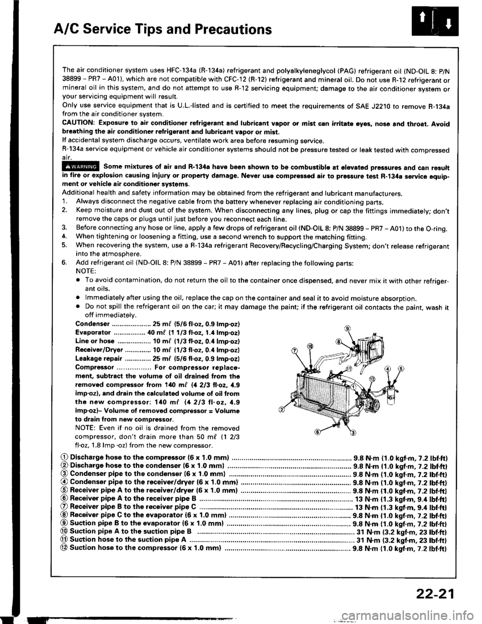
Condenser ..................... 25 m/ (5/6 fl.oz, 0.9 lmp.oz)
Evaporator ................. ilo mf 17 113fl.oz,1.4 lmp.oz)
Line or hose 10 ml (1/3 fl.oz. o.il lmp'ozl
Receiver/Dryer .....,.,,...., 10 m{ l1l3 tl.oz, 0.4 lmp.ozl
Leakage repair .............. 25 mf (5/6 fl.oz, 0.9 lmp.ozl
Compressor For compressor .eplaco-
m€nt, subtract the volumo of oil drained from tho
removed compressor trom 140 ml 11 213 ll.oz, 1,9
imp.ozl, and drain the calculalgd volume of oil from
tho new compressor: 140 mf 11 213 ll. oz, 1.9
imp.ozl- Volume ot removod compressor = Volume
to drain from n€w compressor.
NOTE: Even if no oil is drained from the removed
compiessor, don't drain more than 50 ml 11 213
fl.oz, 1.8 lmp .oz) from the new comDressor.
O Dischargo hose to the compresso. (6 x 1.0 mml .............................. 9.8 N.m {1.0 kgt.m, 7.2 lbf.ft)(, Discharge hosa to ths condenser (6 x 1.0 mm) . 9.8 N.m {1.0 kgf.m, j.Z lbl.ftl@ Condenser pipe to tho condenser (6 x 1.0 mml 9.8 N.m n.O kaf.m,t-2tbl.ftl
@ Condenser pipe to the receiver/dryer (6 x 1.0 mm) ......................... 9.8 N.m (1.0 katm,7.2 lbf.ft)@ Receiver pipe A to tho receiver/dryer 16 x 1.0 mm) ......................... 9.8 N.m (1.0 kttm. 7.2 lbt.ft)@ Receiver pipe A to th6 receiver pipe B ......................................
O Receiver pipe B to the receiver pipe C .............................................. 13 N.m {1.3 kgt.m. 9.4 lbt'ft)
13 N.m {1.3 kgf.m.9.4 lbf'ft)@ Receiver pipe C to the evaporator (6 x 1.0 mm) 9.8 N.m {1.0 kgf.m , j.Zlbl.ftl
@Suaion pip€ B to the evaporator {6x 1.0 mm) ................ ................ 9.8 N.m tt.O t!f.-, r.Z tUt tt}@ Sustion pipe A to the suction pipe B .................. 3t N.m (3.2 klnm,23 lbf.ft)(, Suction hose lo the suction pipe A ................ ...... 31 N.m (3.2 kgf.m, 23 tbf.ftl
OA Suction hose to the compressor {5x 1.0 mm} ................ ................. 9.8 N.m 11.0 kgt.m,7.2 lbf.ft)
ET
22-21
Page 1090 of 1413

A/C System Service
Recovery
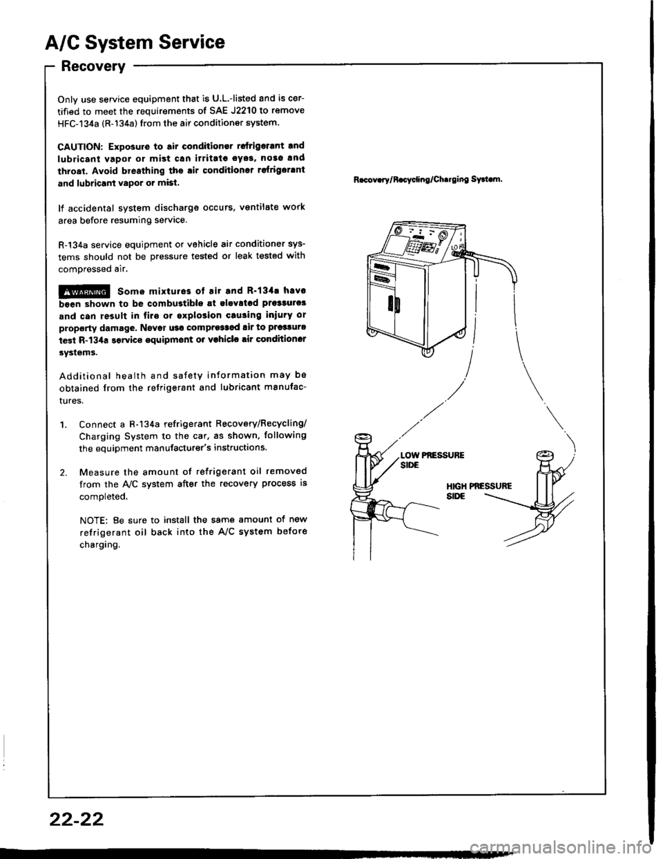
Onlv use service equipment that is U.L.-listed and is cer-
tified to meet the requirements of SAE J2210 to remove
HFC-134a (R-134a) from the air conditioner system.
CAUTION: Expo3ute to air conditioner rcfrigelant rnd
lubricant vapor or mist can irritatc oyo!, no3o and
throat. Avoid bresthing the lir condhionot rofrigorlnt
and lubricant vapor or misl.
lf accidental system discharge occuts, ventilate work
area before resuming service.
R-134a service equipment or vehicle air conditioner sys-
tems should not be pressure tested or leak tested with
comoressed air.
!!@ some mixturos ot Eir and R'134. hsvc
bsen shown to be combu3tible st elavllcd prs33urc3
and can result in fire or oxplosion cau3ing iniurY or
property damage, Nsvor u36 comprg3Sod lir to P|'�3turl
test R-134a servic€ equipmont o. vohiclc rir condhioncr
3ystems.
Additional health and safety information may be
obtained from the refrigerant and lubricant manufac-
rures.
'1. Connect a R-134a refrigerant Recovery/Recycling/
Charging System to the car, as shown, following
the equipment manufacturer's instructions.
2. Measure the amount of refrigerant oil removed
from the A/C system after the recovery process is
comoleted.
NOTE: Be sure to install the same amount of new
refrigerant oil back into the A/C system befote
charging.
R.cov.rylR.cycling/Ch.rging sy.t m.
Pf,ESSUFE
22-22