1994 HONDA INTEGRA charge system
[x] Cancel search: charge systemPage 1091 of 1413
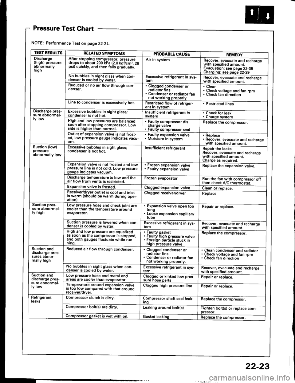
Pressure Test Chart
NOTE: Performance Test on page 22-24.
TEST RESULTSRELATED SYMPTOMSPROAABLE CAUSEREMEDYDischsrge(high) pressureabnormallynrgn
AftEr stopping compressor, pressuredrops to about 200 kPa (2.0 kof/cmr. 28psi) quickly, and then falls gr;dua y.
Air in systemRecover, evacuate and recharqowith sDecified amount. -
Evacuation: see Daqe 22-38Charoino: se6 D;op--2?-?qNo bubbles in sight g16ss when con-denser is cooled bv water.E-\cessive refrigerant in sys-Recover, evacuate and recharqewith specitied amount. -
Reduced or no air flow through con-oenser.Clogged condenser orradiato. finsCondenser o. radiator fannot working properly
CleanCheck voltage and fan rpmunecK lan ofeclton
Line to condenser is excessivelv hot.Restricted flow of refriger-ant In syslem. Restricted lines
Discharge pres-su re abnormal-Excossive bubbles in sight glass;condenser is not hot.Insuff icient refrigerant insyslemCheck for leakCharge systemHigh and low pressures are balancedsoon after stopping compressor. Lowside is higher than normal,
Faulty compressor dis-cnarge vaNsFaulty compressor seal
Replace the compressor.
Outlet of expansion vslve is not frost-ed, low pressure gauge indicates vacu-um,
. Faulty expansion valve. Moisture in sysiem. Replace. Recover, evacuate and recharoewith specified amount. -
Suction (lowlpressureabnormally low
Excessive bubbles in sight glass;conqenser rs not hot_Insuff icient ref rigerantReoair the leaks.Reaover, evacuate and recharoewith sDecifisd amount. -
Charqe as required.Expansion valve is not trosted and lowpressur€ line is not cold. Low pressuregauge Inorcates vacuum.
Frozen expansion valveFaulty expansion valveReplace the expansion valve.
Discharge temperaturg is low and theair flow from vents is restricted.Froren evaporatorRun the tan with comoressor oftthen check Ay'C thermostat.Expansion valve is frost€d.Clogged expansion valveCl€an or replace.Receiver/dryer outlet is cool and inletisrryarm (should be warm during oper-Clogged r€ceiver/dry€rReplace
Suction pres-su re abnormal-ly high
Low pressure hose and check joint arecooler than the temDeraturo aroundevaDorator.
'
ffin"nsion u"lu" oD"n too
. Loose expansion capillary
Repair or replace.
Suction pressure is lowered when con-denser is cooled by water,Excessive refrigerant in sys-remRecover, evacuate and recharqewith sDecifi€d amount. -
High and low pressure are equalizedas soon as the compressor is stopped,and both gauges fluctuate while run-nrng.
Faultv oasketFaulty Figh pressure valveForeign particle stuck inhigh pressure valve
Replace the compressor.
Suction anddischarg€ pres-sufes aonor-mally high
Reduced air flow through condenser.. Clogged condenser orradiator fins. Condenser or radiator fannot working properly.
Clean condenser and radiatorCheck voltage and fan rpmCheck fan direcrion
No bubbles in sight glass when con-cl€nser is cooled bv water.Excessive refrigerant in sys-remRgcover, €vacuate and recharoewith sp€cified amount.Suction snddischarge pres-su r€ abnormal-
Low pressure hose and metal endafeas are cooler than evaDorator.Clogged or kinked tow pre€-sure nos€ pansFepair or replace.
Temperature around expansion valveis too low compared with that aroundrecerver/orver.
Clogged high pressure lineRepair or replace.
Refrig€rantleaksCompressor clutch is dirty.Compressor shaft seal leak-IngReplace the comDressor.
Compressor bolt(s) are dirty.Leaking around bolt(s)Tighten bolt(sl or replace com-pressor.Compressor gasket is wet with oil. IGasket leakingReplace the compressor.
22-23
Page 1092 of 1413
A/G System Service
Performance Test
The performance test will help determine if the air con-
ditioner system is operating within specitications.
Only use service equipment that is U.L.-listed and is cer-
tified to meet the requirements of SAE J2210 to remove
HFC-134a {R-134a) from the air conditioner system.
CAUTION: Exposure to air conditioner relrig€rant and
lubricant vapor ot mist can irritate eyes, nose and
throat. Avoid breathing the air conditioner rstrigerant
and lubricant vapor or mi3t.
It accidental system discharge occurs, ventilate work
area before resuming service.
R-134a service equipment or vehicle air conditioner sys-
tems should not be pressure tested or leak tested with
comPressed atr.
!@ some mixtures ot air and R'1344 hrv6
been shown to be combustibls at elovatod prsssurel
and can result in firg or explosion causing iniury 01
property damage. Ngvor usg compregsed ail to prossuro
t€st R-134a ssrvice equipment or vohicl€ air conditioner
syst€ms.
Additional health and safety information may be
obtained from the refrigerant and lubricant manufactur-
ers.
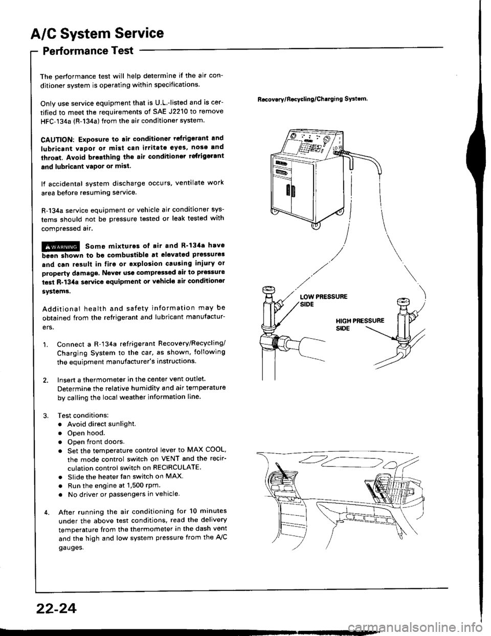
1. Connect a R-134a refrigerant Recovery/Recycling/
Charging System to the car, as shown, iollowing
the equipment manufacturer's instructions.
2. Insert a thermometer in the center vent outlet.
Determine the relative humidity and air temperature
by calling the local weather information line,
3. Test conditions:
. Avoid direct sunlight.
. Open hood.
. Open front doors
. Set the temperature control lever to MAX COOL,
the mode control switch on VENT and the recir-
culation control switch on RECIRCULATE.
. Slide the heater fan switch on MAX
. Run the engine at 1,500 rPm
. No driver or passengers in vehicle.
4. After running the air conditioning for 10 minutes
under the above test conditions. read the delivery
temperature from the thermometer in the dash vent
and the high and low system pressure from the A,/C
gauges.
Rocov.rylB.cycling/Ch!lging SFtrm.
PRESSURELOW
22-24
Page 1094 of 1413
Evaporator
Replacement
CATION:
. All SRS eloctrical wiring harnesses are coverod with
yollow in3ulation.
. B€tore disconnocting 8ny part of tho SRS wire har-
nsss, conngqt th€ 3hort connestor{sl.
. Roplaca ths entire aftected SRS harness a$embly if
it has an op€n circuit or damaged wiring.
lcove.ed with yellow insulation)
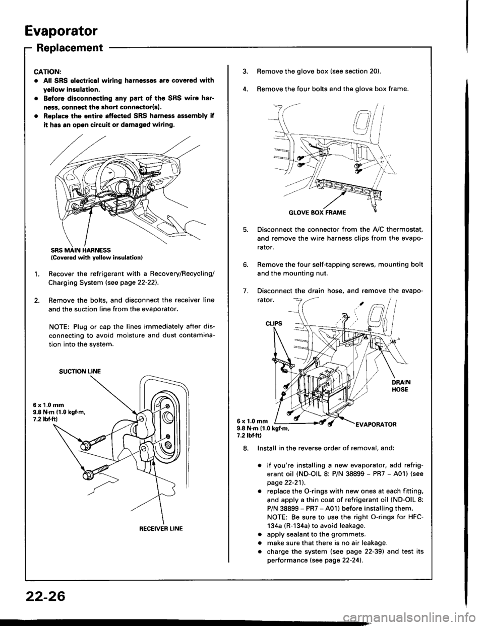
Recover the refrigerant with a Recovery/Recycling/
Charging System lsee page 22-22]-.
Femove the bolts, and disconnect the receiver line
and the suction line from the evaporator.
NOTE: Plug or cap the lines immediately after dis-
connecting to avoid moisture and dust contamina-
tion into the svstem.
2.
L
6x1.0mm9.8 N.m {1.019f.m,1.2 tbl.ttl
SUCTION LINE
RECEIVEB LINE
3.Remove the glove box (see section 20).
Remove the four bolts and the glove box frame.
Disconnect the connector from the Ay'C thermostat,
and remove the wire harness clips from the evapo-
rator.
Remove the four self-tapping screws, mounting bolt
and the mounting nut.
Disconnect the drain hose, and remove the evapo-
rator.
1.
6x1.0mmAPORATOR9.8Nm{1.0kg{.m,7.2 tbtft)
a
a
8. Install in the reverse order of removal. and:
it you're installing a new evaporator, add refrig-
erant oil (ND-OIL 8: P/N 38899 - PR7 - A01) (see
page 22-2'll.
replace the O-rings with new ones at each fitting.
and apply a thin coat of refrigerant oil (ND-OlL 8:
P/N 38899 - PR7 - A01l before installing them.
NOTE: Be sure to use the right o-rings for HFC-
134a {R-134a} to avoid leakage.
apply sealant to the grommets.
make sure that there is no air leakage.
charge the system (see page 22-39) and test its
performance (see page 22-241.
22-26
Page 1103 of 1413
Condenser
Replacement
RAOIATOR UPPENMOUNT BRACKETS
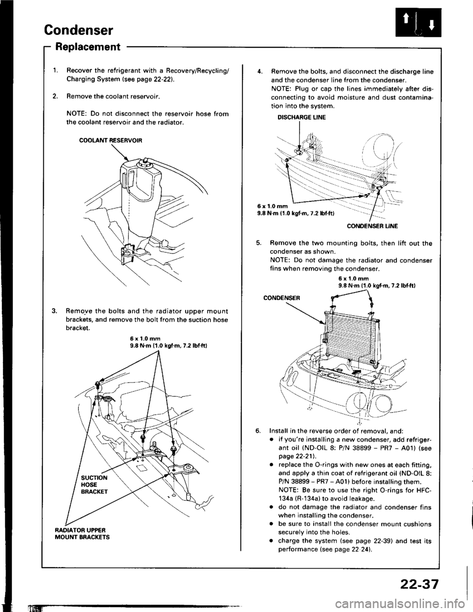
Recover the relrigerant with a Becovery/Recycling/
Charging System (see page 22-221.
Remove the coolant reservoir,
NOTE: Do not disconnect the reservoir hose from
the coolant reservoir and the radiator.
COOLANT RESERVOIR
Remo.ve the bolts and the radiator upper mount
brackets, and remove the bolt from thg suction hose
bracket.
9.8 N.m {1.0 kgf.m.7.2 lbtftl
'1Iffi
22-37
6x1.0mm9.8 N.m (1.0 kgl.m,7.2 lbt.ft)
......-.....
CONOENSER LINE
Remove the bolts. and disconnect the discharge line
and the condenser line from the condenser.
NOTE: Plug or cap the lines immediately after dis-
connecting to avoid moisture and dust contamina-
tion into the system.
DISCHARGE LINE
Remove the two mounting bolts, then lift out the
condenser as shown.
NOTE: Do not damage the radiator and condenser
fins when removing the condenser.
6x1.0mm9.8 N.m (1.0 kgf.m, 7.2 lbl.tt)
Install in the reverse order of removal. and:
. if you're installing a new condenser, add refriger-
ant oil (ND-OIL 8: P/N 38899 - PR7 - A01) (see
page 22-21t,.
. replace the O-rings with new ones at each fitting,
and apply a thin coat of refrigerant oil {ND-OIL 8:
P/N 38899 - PR7 - A01) before installing them.
NOTE: Be sure to use the right O-rings for HFC-
134a (R-134a) to avoid leakage.
a do not damage the radiator and condenser fins
when installing the condenser,
. be sure to install the condenser mount cushions
securely into the holes.
. charge the system (see page 22-39) and test its
performance (see page 22 24!�.
Page 1104 of 1413
A/G System Service
Evacuation
Only use service equipment that is U.L.-listed and is cer-
tified to meet the roquirements of SAE J2210 to remove
HFC-134a (R-134a) lrom the 8ir conditioner system.
CAUTION: Exposulo to 6ir conditioner refligorrnt and
lubricani vapor or mi3t crn i.ritato 9y33, noaa and
thrort. Avoid bratthing ths .ir conditionor rsfrigorrnt
snd lubricsnt vtpor or mist.
lf accidental system discharge occurs, ventilate work
area before resuming service.
R-134a service equipment or vehicle 8ir conditioner sys-
tems should not be pressure tested or leak tested with
compressed ait.
!@ somo mixtuto3 ot ril and R'134! hav.
been shown to bo combustible at olevltad prossulo3
and can re3ult in fire or explosion crusing inlurY or
property damago, Navor us! comprossod air to prgsauro
test R-13/aa 3orvicr €quipmlnl or vohiclo air conditionol
sy3lems.
Additional health and safety information may be ob-
tained from the retrigerant and lubricant manufactures.
1. When an Ay'C System has been opened to the atmo-
sDhere, such as during installation or repair, it must
be evacuated using a R-134a refrigerant Recovery/
Recycling/Charging System. {lf the system has been
open for several days, the receiver/dryer should be
replaced.l
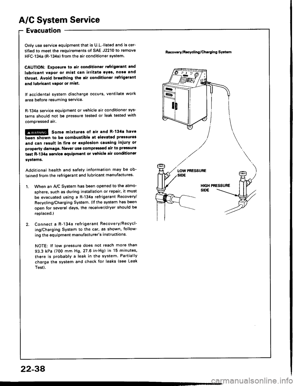
2. Connect a R-134a refrigerant Recovery/Recycl-
ing/Charging System to the car, as shown, follow-
ing the equipment manufacturer's instructions.
NOTE; lf tow pressure does not reach more than
93.3 kPa (700 mm Hg, 27.6 in'Hg) in 15 minutes,
there is probably a leak in the system. Partially
charge the system and check tor leaks {see Leak
Test).
R.cov.ry/R.cycling/Chtroing Syttom
PRESSUREaotnSIDE
2234
Page 1106 of 1413
A/C System Service
Leak Test
Only use service equipment that is U.L.-listed and is cer-
tified to meet the requirements of SAE J2210 to remove
HFC-134a (R-134a) from the air conditioner system.
CAUTION: Exposura to air condition ratrigerant and
lubaicant vapor or mist can irritato oyes. nose and
throat. Avoid br€athing tho sir conditionsr reftigolant
and lubricant vapor or mist.
lf accidental svstem discharge occurs, ventilate work
area before resuming service.
R-134a service equipment or vehicle air conditioner sys-
tems should not be pressure tested or leak tested with
comoressed air.
@ some mixturos ot air and R'13'la have
b.6n shown to b€ combustible at glsvated pressur€s
and can result in firo or sxplo3ion causing iniury or
proporty damage. Ngvar uso compress€d tir to pro33ure
tost R-134a $rvics oquipmont or vohicl€ air Gonditionsr
systcms.
Additional health and satetY information may be ob-
tained from the refrigerant and lubricant manufactures'
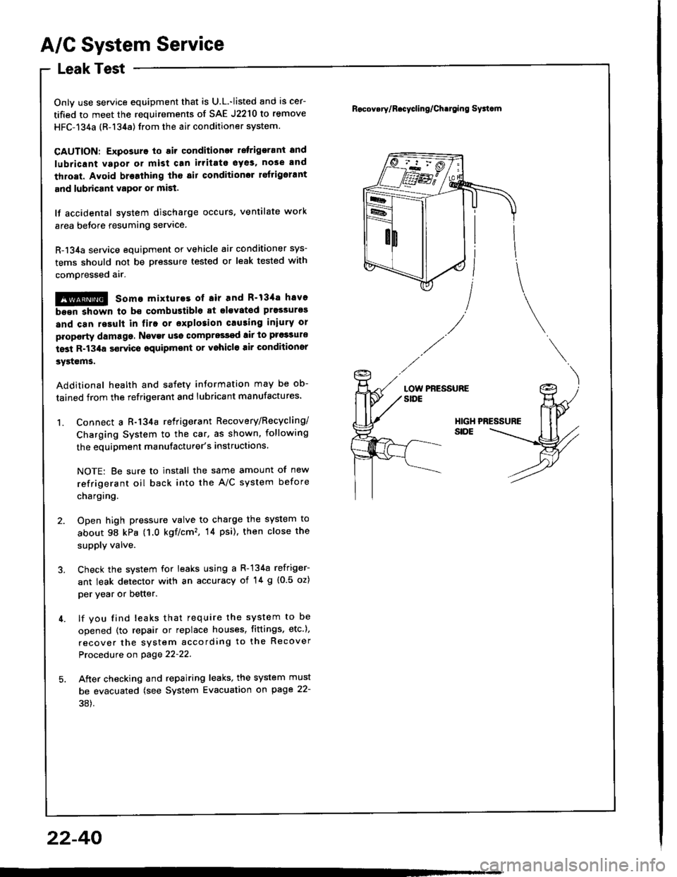
1. Connect a R-134a retrigerant Recovery/Recycling/
Charging System to the car. as shown, following
the equipment manufacturer's instructions.
NOTE: Be sure to install the same amount of new
refrigerant oil back into the A/C system before
chargtng.
2. Open high pressure valve to charge the system to
about 98 kPa (1.0 kgf/cm'�, 14 psi), then close the
supply valve.
3. Check the system for leaks using a R-134a refriger-
ant leak detector with an accuracy of '!4 g {0.5 oz)
per year or better.
4. lf you find leaks that require the system to be
opened (to repair or replace houses, fittings, etc.),
recover the system according to the Recover
Procedure on page 22-22.
5. Aiter checking and repairing leaks, the system must
be evacuated (see System Evacuation gn page 22-
38).
Rocov.ry/R.cycling/Ch.tging Sy3tcm
LOW PRESSURESIDE
HIGHSIDE
22-40