Page 1176 of 1413
lgnition Switch
CAUTION:
a All SRS electdcal wiring harnessss aro covotod whh
yollow insulation.
a Botore disconnocting any part ot th6 SRS wiro har-
n6ss. connoct tha shon connoctor(t).
a Replac€ tho ontiro affected SRS hames! asllmbly It
it has an op6n circuit 01 damagod widng.
1. Remove the dashboard lower cover and knee bolster.
KNEE BOLSTERDASHBOARD LOWER COVER
Disconnect the 5-P connector flom the undsr-dash
fuse/relav box and the 7-P connector from the main
wire harness.
23-70
SRS MAIN HARI{ESS(Cov6red with Yollow inrulltiori)
J.Chsck tor continuity b€tween the terminals in each
switch position according to the table.
4. lf continuity checks do not agre€ with the tabl6,
reolace the €lectrical part of the switch lsee page
23-72t.
Terninal
P6itionBATtG1ST
--o
o-
I
Page 1177 of 1413

Electrical Switch Replacement
a All SRS €lectric8l wiring hamosses ar€ covorsd withyellow insulation,
a Befora disconnecting any pan of tho SRS wilo har-neas. connect the short connoctor(sl.a R6place the entire attect6d SFS harness assombly ifit has an opon circuit 01 damaged wiling.
NOTE: The original radio has a coded theft protection
circuit, Be sure to get the customer's code number before- disconnecting the battery.- removing the No. 32 (7.5 Al fuse from the under-hoodluse/relay box.- removang the radio.
After service, reconnect power to the radio and turn iton. When the word "CODE" is displayed, enter the cus-tomer's 5-digit code to restore radio ope.ation.
1. Disconnect the negative cable from the batery.
2. Remove the dashboard lower cover and knee bolster
{see page 23-70).
3. Disconnect the 5-P connector from the under-dashfuse/relay box and the 7-P connector from the mainwire harness (see page 23-70).
E
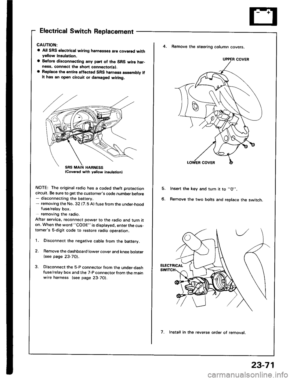
4. Remove the steering column covers.
Insert the key and turn it to ,,O',.
Remove the two bolts and replace the switch.
UPPER COVER
7. Install in the reve.se orde. of removat.
23-71
Page 1178 of 1413

lgnition Switch
Steering Lock Replacement
CAUTION:
a All SRS electrical wiring harnesses ale covsred with
yellow insulation.
a Belore disconnecting any parl ot the SRS wir€ hal-
ness, connecl the short connector{s).
a Replace the entire alfected SRS harness a$6mbly il
it has an open circuit or damaged wiring.
NOTE: The original radio has a coded thett protection
circuit. Be sure to get the customer's code number betore
- disconnecting the batterY.
- removing the No. 32 (7.5 A) fuse from the under-hood
fuse/relay box.- removing the radio.
After service, reconnect power to the radio and turn it
on. When the word "CODE" is displayed, enter the cus-
tomer's 5-digit code to restore radio operation.
1. Disconnect the negative cable from the battery.
2. Remove the dashboald lower cover and knee bolster
(see page 23-7'l ).
3. Disconnect the 5-P connector from the under-dash
fuse/relay box and the 7-P connector trom the main
wire harness {see page 23-71).
4. Remove the steering column covers (see page
23-711.
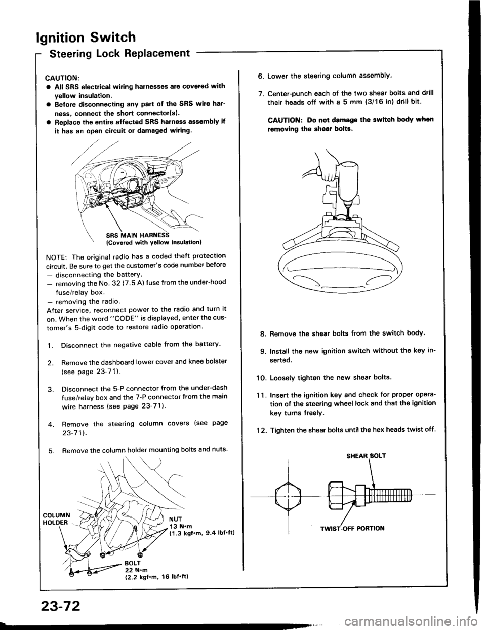
5. Remove the column holder mounting bolts and nuts'
BOLT22 N.m
12.2 kgl'm.
NUT13 N.m(1.3 kgf.m, 9.4 lbl'ftl
23-72
16 tbt.ftl
6. Lower the steering column sssembly.
7. Center-Dunch each oJ the two shear bolts and drill
their heads off with a 5 mm {3/1 6 in) drill bit'
CAUTION: Do not dama96 tho switch body whon
r€movlng the shoar bol$.
Remove the shear bolts from the switch body.
Install the new ignition switch without the key in-
serted.
Loosely tighten the new shear bolts.
Insert the ignition key and check for proper opera-
tion of the steering wheel lock and that th€ ignition
key turns freely.
Tighten the shear bolts untilthe hex heads twist off.
8.
q
10.
11.
12.
Page 1219 of 1413
Gauge Assembly
Component Location Index
CAUTION:
a All SRS electrical wiring harnosses are cov€rod withyellow insulation.
a Bofore disconnecting any prn ot th€ SRS wire har-ness, connect tho short connector(sl.a R€place th6 entirs affGcted SRS halne$ assembly ifit has an open circuit o? damaged wiring.
SRS MAIN HARNESS{Cov.r6d with yollow inrularionl
GAUGE ASSEMBLYGauge Location Index, page 23-114Indicator Location Index, page 23-1 14Terminal Location Index, page 23-114Bulb Location. page 23-'l 15Disassembly. page 23-1 19Removal, page 23-118
FUEL GAUGE SENDING UNtTTest, page 23'124Repfacemenr, page 23-124
VEHICLE SPEEO SENSOB IVSS}Test, page 23-120fnput Test. page 23-120Repfacement, page 23-122
PARKITTG BRAKE SWITCHTest, page 23-127
BRAKE FLUID LEVEL SWITCHTesr, page 23-127
EI{GINE OIL PBESSURE SWITCHTest, page 23-122
ENGINE COOLANT TEMPERATURE IECTI GAUGESENOING UNITTest, page 23-126
(C61'ios tho SBS indicator signal)
23-113
Page 1220 of 1413
Gauge Assembly
Gauge/lndicator/Terminal Location Index
CAUTIOI{:
a All SRS olectrical wiring harnessos aro covorod with
yellow insulation,
Belol€ disconnecting any part ot tho SRS wiro hat-
nesa. connoct the short connoctol(El.
Replaco th6 entire aff6cted SRS hamess sssombly lf
it has an open circuil or damagod widng.
co r{EcroR "c" (c558}
FUEL GAUGE:Gauge Test, page 23-123
Sending Unit Tost, page 23-124
23,-114
A/T GEAR POSIT|OIIDICATOR SYSTEISee pags 23-132
E GI[{E COOLAI{T TEIIPEFATURE IECTIc6uge TEst, p6g6 23-126Sending Unit Tsst, pago 23-126
TACHOMETER:Indicatos lOO rpm at20O puls€s per minul€of the ignition controlmodul€ llCM).
SPEEDOMETER:Indicates (60 mph 6i 1025 rpml or{60 km/h at 637 rem) of th€v€hicle spe6d sonsor lVSSl.
CoNNECTOR "8" (c5601
Bi ----------+ B16Cl ----+ClO
f',. /i)
)Y
-"b
\_./ \J \-___--
a1 -----> A5
Dl-------.>D13
col{]{ECTOR "D" (C5591
rtrF --
coNNECfOR "A" (C557)
Page 1231 of 1413

Low FuelIndicator
IndicatorLight Test
Seat Belt Reminder
System
Seat Belt Switch Test
J.
NOTE: Reter to page 23- 1 1 6 tor the wiring description
of the low fuel indicator circuit.
1. Park car on level ground.
@ oo not rmoko whil6 working on th€
fuol system, Keop op€n llamg3 awsy from your work
area. Drain fuel only into an approvod container,
Drain tuel into an 8pplov€d container. Then install
the drain bolt with a new washer.
Add less than 8.2 t (2.2 U.S.Gal, 1.8 lmp.Gal) of fuel
and turn the ignition switch ON (ll). The low fuel in-
dicator light should com€ on within lour minutes,
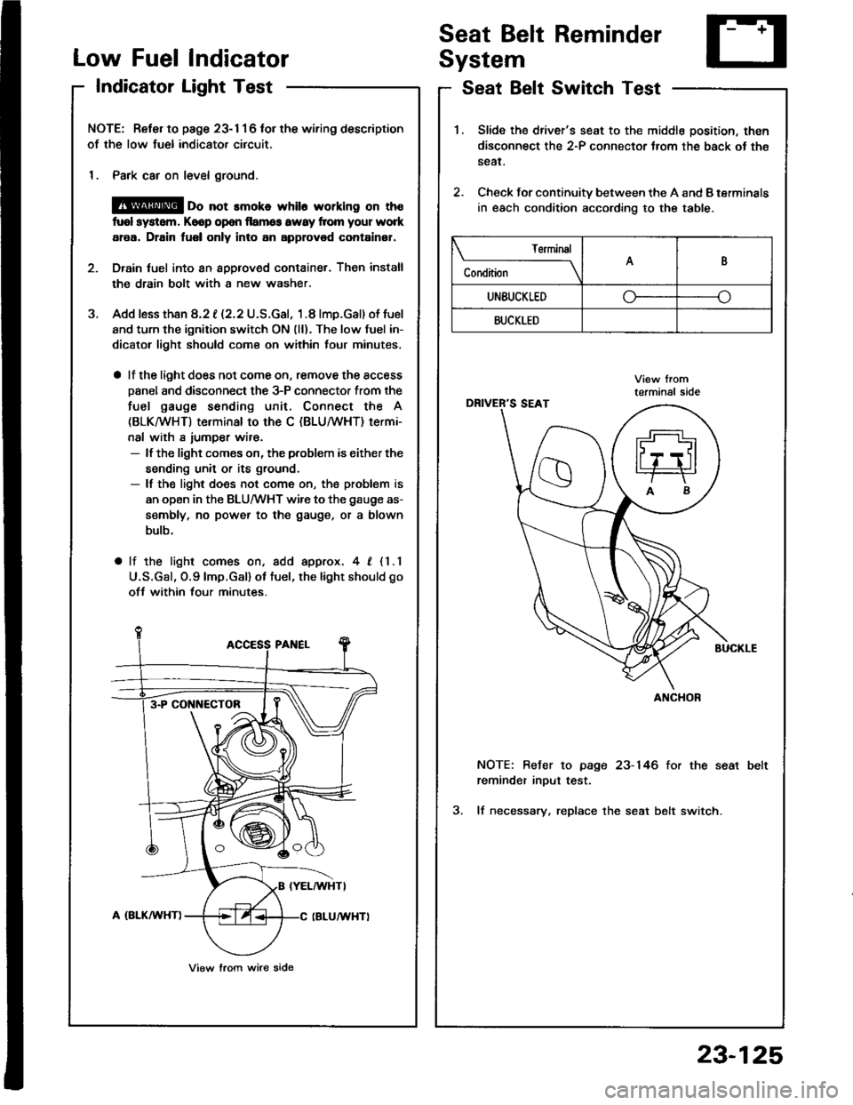
a lf the light does not come on, remove the access
Danel and disconnect the 3-P connector from the
fuel gauge sending unit, Connect the A
(BLKMHT) terminal to the C (BLU/WHT) termi-
nal with a iumper wir€.- lf the light comes on, the problem is either the
sending unit or its ground.- lf the light does not come on, the problem is
an open in the BLU/WHT wire to the gauge as-
sembly, no power to the gauge, or a blown
bulb.
a lf the light comes on, add approx. 4, {1.1
U.S.Gal, O.9lmp.Gal) ot tuel, the light should go
ofJ within four minutes.
3-P CONI{ECTOB
View lrom wire side
1.Slide the driver's seat to the middle position, then
disconnect the 2-P connector Jrom the back ot th€
sear.
Check for continuity between the A and B terminals
in each condition according to the table.
2.
NOTE: Befer to page 23-146 for the seat
reminder inout test.
3. lf necessary. replace the seat belt switch.
Terminal
C"** \AB
UNEUCKLEDo--o
BUCKLED
ANCHOR
23-125
Page 1232 of 1413

GaugeTest
NOTE: Refer to page 23-116 fot the wiring description
oJ the engine coolant temperature (ECT) gauge circuit
diagram.
1. Check the No. 15 (10 A) fuse in the under-dash
tuse/relay box before testing.
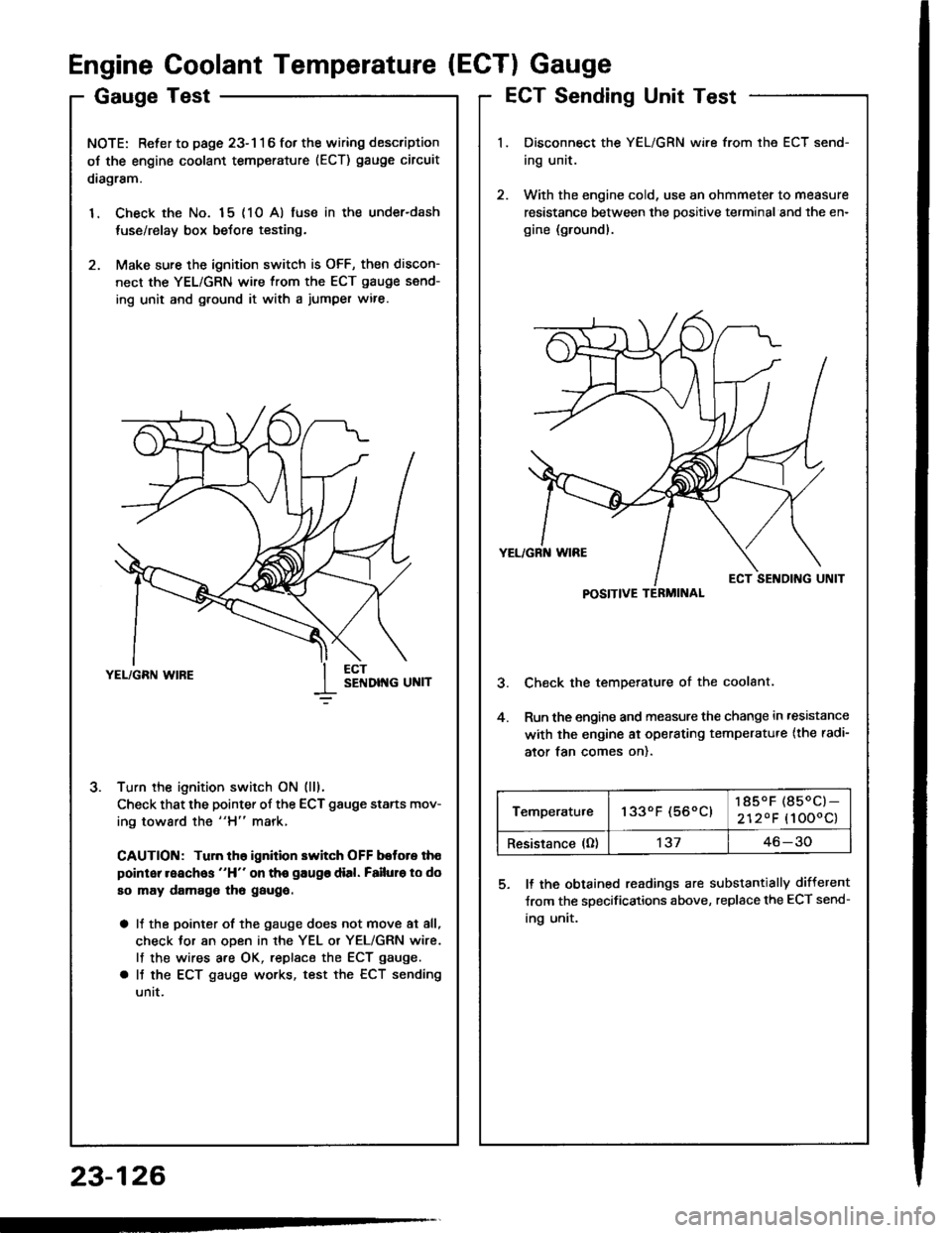
2. Make sure the ignition switch is OFF, then discon-
nect the YEL/GRN wire from the ECT gauge send-
ing unit and g.ound it with a jumper wire.
Turn the ignition switch ON (lll.
Check that the pointer of the ECT gauge starts mov-
ing toward the "H" mark,
CAUTION: Tuln th6 ignition switch OFF botore th€
point reaches "H" on tho gaugo dial. Failuro to do
so may damago tho gaugo.
a It the pointer of the gauge does not move at all,
check Jor an oDen in rhe YEL or YEL/GRN wire.
lf the wires are OK, replsce the ECT gauge.
a It the ECT gauge works, test the ECT sending
untt.
J.
Engine Coolant Temperature (ECTI Gauge
ECT Sending Unit Test
Disconnect the YEL/GRN wire from the ECT send-
ing unit.
With the engine cold, use an ohmmeter to measure
resistance between the positive terminal and the en-
gine (ground).
Check the temperature of the coolant.
Run the engine and measure the change in ,esistance
with the engine ai operating temperatu.e {the radi-
ator tan comes on).
5. ll the obtained readings are substantially different
Jrom the specifications above, replace the ECT send-
ing unit.
23-126
POSITIVE TERMINAL
Temperatu.e1330F (560C)185.F (850C)-
2120F (1000c)
Resistance (O)'t3746-30
Page 1234 of 1413
Maintenance ReminderSystem
Gomponent Location Index
23-128
CAUTION:
a All SRS eloctrical wiring haln€sses are coveled with
y€llow insulation.
a Bsfore disconnocting any part of the SRS wire har-
ne6a, connect tho shon connoctor(s).
a Replace the entire affoctod SRS hsrness ass6mbly if
it has an open circuil or damag€d wiring.
MAINTENAf{CE REMINDER LIGHT(ln th6 gaugo 63.smblylGauge Assembly. page 23-113
VEHICLE SPEED SENSOR {VSS){On the t.ansmirsion houainglTest, page 23-120, 121Input Test, page 23-120Repfacement, page 23-122
MAINTENANCE REMINDER UNITlBohind tho dashboard lowor covor)Input Test, page 23-131
MAINT
REOD