Page 1364 of 1413
Wipers/Washers
Wipers/Washers Switch Test
5
4
CAUTION:
a All SRS electrical wiring harn6ss6s alo covered with
yellow insulation.
a Belore dkconnecting any part ot th6 SRS wire har-
neaa. connect the short connoctor(sl.
a Replac6 the 6ntire affoctod SRS harness assembly it
it has an open cilcuit 01 damaged wiring.
1. Remove the steering column covers.
2. Disconnect the 8-P and 6-P connectors Jrom the
swatch.
It necessary, remove the two screws and the switch.
Check for continuitv between the terminals in each
switch position according to the table.
scREws
SRS iIAIN HARNESS
{Covor.d rvilh yollow inrulation}
IJK ABCD
23-258
Page 1371 of 1413
Supplemental Restraint System
(sRst
Gomponent Location Index .................. 23-266
Description ..23-267
Circuit Diagram 23-268
Wiring Locations 23-270
Precautions/Procedures ..23-271
Troubfeshooting ............. ..23-276
Airbag Assembly
Repfacement .................. 23-295
Disposal ....23-299
Cable Reel
Replacement .................. 23-301
Dash Sensor
Replacement .................. 23-305
SRS Unit
Replacement .................. 23-307
Page 1375 of 1413
Supplemental Restraint System (SRSI
Wiring Locations
CAUnON: Make sure all SRS ground locrtion3 lrc clrln rnd ground3 tra |.curalv rltachad.
NOTE:
o Alt SRS electricsl wiring harnesses are covered with ysllow insulation.
. RsDlace the entire affected SRS harness assembly if it has an open circuit or damaged wiring.
CABIE REEL to DdrrEFS AnaAC3+ OOI{iECTOR
DASHBOARD WIRE HARNEi9to INDICATOB UGHT in GAUGE ASSEMBLY
5-P CONNECTOBaFs irA[t H^RiEssto FROiIT PASSEMIEFS Ana G3t coftf'Eclon
SRS MAIN HARNESS tO
MAIN WIRE HARNESS+P OONNECTOR
C. b Ra nod.ll
SnS Alt{ ll^ntc8s too sH SErson2+ OOt{tlEcT()R
SRS MAIN HARNESSto UNDER-DASHFUSE/RELAY BOX2"P @NNECTOR
MAIN WIRE HARNESSto DASHBOARD WIREHARNESSlGP CONNECTOR
SBS MAIN HARNESS toLEFT DASH SENSOR2.P CONNECTOA
23-270
Page 1377 of 1413

Supplemental Restraint System (SRSI
Wiring Precautions
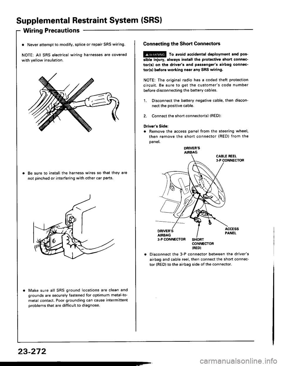
o Never attempt to modify. splice or repair SRS wiring.
NOTE: All SRS electrical wiring harnesses are covered
with yellow insulation.
Be sure to install the harness wires so that they are
not pinched or interfering with other car pans.
Make sure all SRS ground locations are clean and
grounds are securely fastened for optimum metal-to-
metal contact. Poor grounding can cause intermittent
problems that are difficult to diagnose.
23-272
Connecting the Short Connectors
@ To avoid accident8l deploymont and pos-
5ibl6 iniury, slways insiall the protectiva short connec-
tor(s) on tho drivgr'3 and passengor's airbag connec.
tor(s) be{ore working noar any SRS wiring.
NOTE: The original radio has I coded theft protection
circuit. Be sure to get the customer's code number
before disconnecting the battery cables.
1. Disconnect the battery negative cable. then discon-
nect the Dositive cable.
2. Connect the short connector(s) {RED):
Driver's Side:
. Remove the access panel from the steering wheel.
then remove the short connector (RED) from the
Daner.
DRIVER'SAIRBAG
CONNECTORIREDI
Disconnect the 3-P connector between the driver's
airbag and cable reel, then connect the short connec-
tor {RED} to the airbag side oi the connector.
Page 1380 of 1413

Sensor Inspection
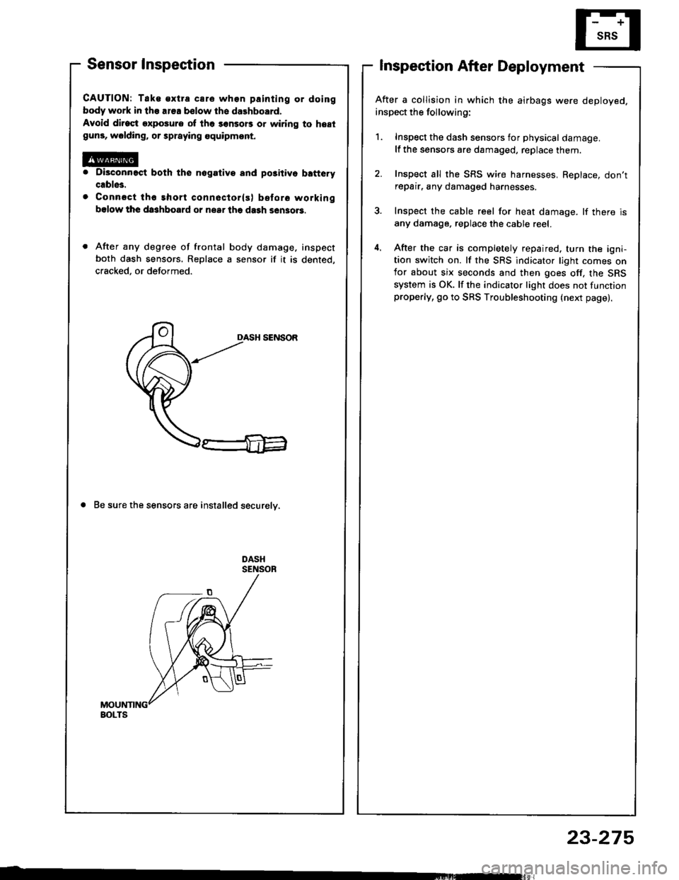
CAUTION: Tak€ €xtra care whon painting or doing
body work in the ar€a bslow th6 dalhboard.
Avoid dirost exposure ot lh6 sonsors or wiring to hestguns, wolding, or spraying equipmont.
Di3connact both the nogativo and po3itivo b!ftery
cable3.
Connsct tho short conneclor(s) before working
bslow the da3hboard or nsar lhe dash sen3o.3.
After any degree of frontal body damage, inspect
both dash sensors. Replace a sensor if it is dented,
cracked, or deformed.
DASH SENSOR
a Be sure the sensors are installed securelv,
Inspection After Deployment
After a collision in which the airbags were deployed.
inspect the following:
1. Inspect the dash sensors for physical damage.
lf the sensors are damaged, replace them.
2. Inspect all the SRS wire harnesses, ReDlace, don'trepair, any damaged harnesses.
3. Inspect the cable reel for heat damage. lf there is
any damage. replace the cable reel.
4. After the car is completely repaired. turn the igni-tion switch on. lf the SRS indicator light comes onfor about six seconds and then goes off, the SRS
system is OK. lf the indicator light does not functionproperly, go to SRS Troubleshooting (next page).
BOLTS
23-275
Page 1381 of 1413

Supplemental Restraint System (SRSI
Troubleshooting
Self-diagnosis Function
The SRS unit includes a self-diagnosis function. lf there
is a failure in the sensors. SRS unit, inflator, or their cir-
cuits, the SRS indicator light in the gauge sssembly
comes ON.
As a system check, the SRS indicator light also comes
on when the ignition is first turned ON to the (ll) posi-
tion. lf the light goes off after approximately six sec-
onds, the system is OK.
lf the SRS indicator lighr remains on (or fails to come on
in the system check mode), one of the SRS components
(or the wiring/connectors inbetween) is laulty
Troubleshooting Precautions
a Always use the test harness. Do not use test probes
directly on component connector terminals or wires;
you may damage them or the SRS unit.
a When connecting any of the test harnesses to the
system, push the connectors straight-in; do not bend
the connector terminals,
. Before disconnecting any part of the SRS wire har-
ness, connect the shon connector (RED) on the driv-
er's airbag. On cars equipped with a front passen-
ger's airbag, connect short connectors on the driver's
airbag and the front passenger's airbag.
SRS Indicator Light Troubleshooting
Possiblo conditions:
1. SRS indicator light does not come on at all - see
page 23-278.
2. SRS indicator light stays on constantly - see page
23-242.
3. SRS indicator light comes on in combination with a
failure of another electrical system (charging sys-
tem light). Check for damage/corrosion at the
under-dash tuse/relay box connector.
NOTE:
. Before starting the applicable troubleshooting. check
the condition of all SRS connectors and ground
points.
. lf the fault is not found after completing the applica-
ble troubleshooting, substitute a known-good SRS
unit and check whether the indicator light goes off.
23-276
MAIN HARNESS
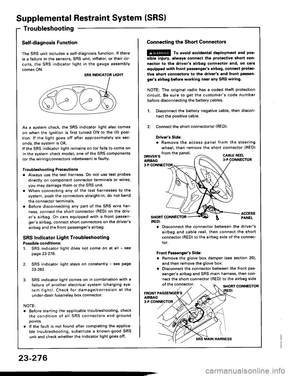
Connecting the Short Connectors
@ To avoid.ccidental doploymont and pos.
siblo iniury. alway3 connect ths protoctive short con.
noctor to tha driver's airbag connectot and, on caf!
equippod with front passongor's airbag, conncqt Prolac-
tivs ghort connoctors to the d.ivsr's and tront passsn-
gar's airbag before working nsai any SRS wiring.
NOTE: The original radio has a coded theft protection
circuit. Be sure to get the customer's code number
before disconnecting the battery cables,
Disconnect the battery negative cable, then discon-
nect the oositive cable.
Connect the short connector(s) (RED):
Drivsr's Sido:
. Romove the accoss panel trom the steering
wheel, then remove the shon connector (BED)
1.
2.
from the panel.DRIVER'SAIRBAG
CABLE R€EL
3-P
ACCESSPANELSHONT CONNESTOR(REDI
. Disconnect the connector between the driver's
airbag and cable reel, then connect the short
connector {RED} to the airbag side of the connec-
tor.
Front Pas€ngo/s Sido:
. Remove the glove box damper (see section 20),
and then remove the glove box.
. Disconnect the connector between the front pas-
senger's airbag and SRS main harness, then con-
nect the short connector (RED) to the airbag side
of the connector,SHORT CONNECTOR
Page 1402 of 1413
CAUTION: Bo 3uro to in3tsll tho SRS wiring so that it isnot pinchod or intoforing with other car parts.
4. Install the new airbag(s):
Driver's Sido: Place the driver's airbag assembly inthe steering wheel, and secure it with new TORX@bolts.
TORXC BOLT9.8 N'm 11.0 kgt m.7.2lbf.ftl Replace.Uio a TORXO T30 bit
TORXO BOLI9,8 N'm l'1.0 kgf.m,7.2lbtftl Replaco.Us. . TORX6 T30 bit
Front Pa$aogsr's Sid€:
. Place the front passenger's airbag assembly in thedashboard.
Loosely install all four mounting nuts.
Tighten the upper two nuts first, then the lowsr twonuts. Adjust the lower mounting bracket if necessarV.
FRONT PASSENGER'SAIRBAGASSEMALY
UPPERMOUNTING NUTS
LOWERMOUNTING NUTS9.8 N.m (1.0lgtm, t.2lbtftlReolace.
CONNECTORIREDI
{cont'd)
23-297
Page 1410 of 1413
Dash Sensor Replacement
GAUTION:
. Oo not drmrgc the sensor wiring.. Do not instrll used SBS part3 from anothor c!t,When repairing an SRS: use only new part3.o Roplaco. 3onsor it it is dented, crackod, or doform.od.
NOTE; The original radio has a coded theft protectioncircuit. 8e sure to get the customer,s code numberbefore disconnecting the b€ttery cabres,
1. Oisconnect the battery negative cable and then theposative cable.
2. Remove the glove box damper (see section 201.then remove the glove box.
SHOBT CONNECTORIREDI
3. Connect the short connector(s) to the airbag(s).
DRIVER'SAIRBAG
DRNEN'SANAAG3.P CONNECTORSHORTCONNECTORIREDI
SRS MAIN HARNESS
Remove the footrest driver,s side only and door sillmolding, then pull the carpet back, and remove thedash sensor protector. (Left side shownj right sideis similar.)
DASHPROTECTOR
5. Remove the two mounting bolts. then remove thedash ssnsor.
(cont'd)
DASH SENSOB
MOUNTIITG BOLTS
23-305