Page 997 of 1413
Front and Rear Consoles
Replacement
SRS wire harnesses are routed near the front console.
CAUTION:
a All SFS electrical wiring harnesses aro coverod
with y6llow insulalion.
a Betore disconnecting any part of lho SRS wire
harness, connect th€ short connoctorc (so€ pago
20-272t.
a Replaco tho sntilo aftocted SRS halness assom-
bly it it has an opon circuit or damaged wlring.
FBONTPASSENGER'S AIRBAG
20-128
NOTE: Take care not to scratch the tront and rear con-
soles, and dashboard.
1. Remove the access cap.
CAUTION: liYhen prying with a flat tip scr€wd.lv€r,
wrap it with protoctivo tape to provent damag€.
ACCESS CAP
2. Remove the sctews.
v : Scraw loc€tlona
At : Scr.w, 2 Bv : Scrow, 2
E)
w)
Page 1000 of 1413

Dashboard
Component Removal/lnstallation
SRS wire harnesses are routed near the dashboard andsteering column.
CAUTION:
a All SRS olectrical wiring harnesses ar6 covolodwith yallow insulation.
a Betoro disconnecting any paft ot th6 SRS wiro
harn€ss, connoct th€ shoi connectots (s66 page
23-2721.
a Replaco th€ entire Itlocted SRS hsrness asaem-
bly il h has an open circuh or damagod wiring.
CAUTION: Whan prying with a flat tip scrowdiv... wrapit with protoctiv€ tape, and apply protectivo tapo a.oundth€ felatsd parts. to provent damag€.
Instiumont p8n6l, Dashboad lower covor. Knec bobtcframoval:
l. Lower the steering column.
2. Remove the screws and detach the cliDs, then re-
move the instrument panel.
3. Remove the coin oocket.
4. Remove the screws and detach the clips, then re-
move the dashboard lower cover.
Disconnect the connector.
: Scrawlocation3, 5
AIF|]A\g)
A i Clip locationg
AA: Cllp, 2 B> : Clip, 2
I l-l L'l| ,-__-, )
itrvi
) 4Z)
_:n,,4<-ft
INSTRUMENT PAI{EL
(cont'd)
COIN POCKET
20-131
Page 1005 of 1413
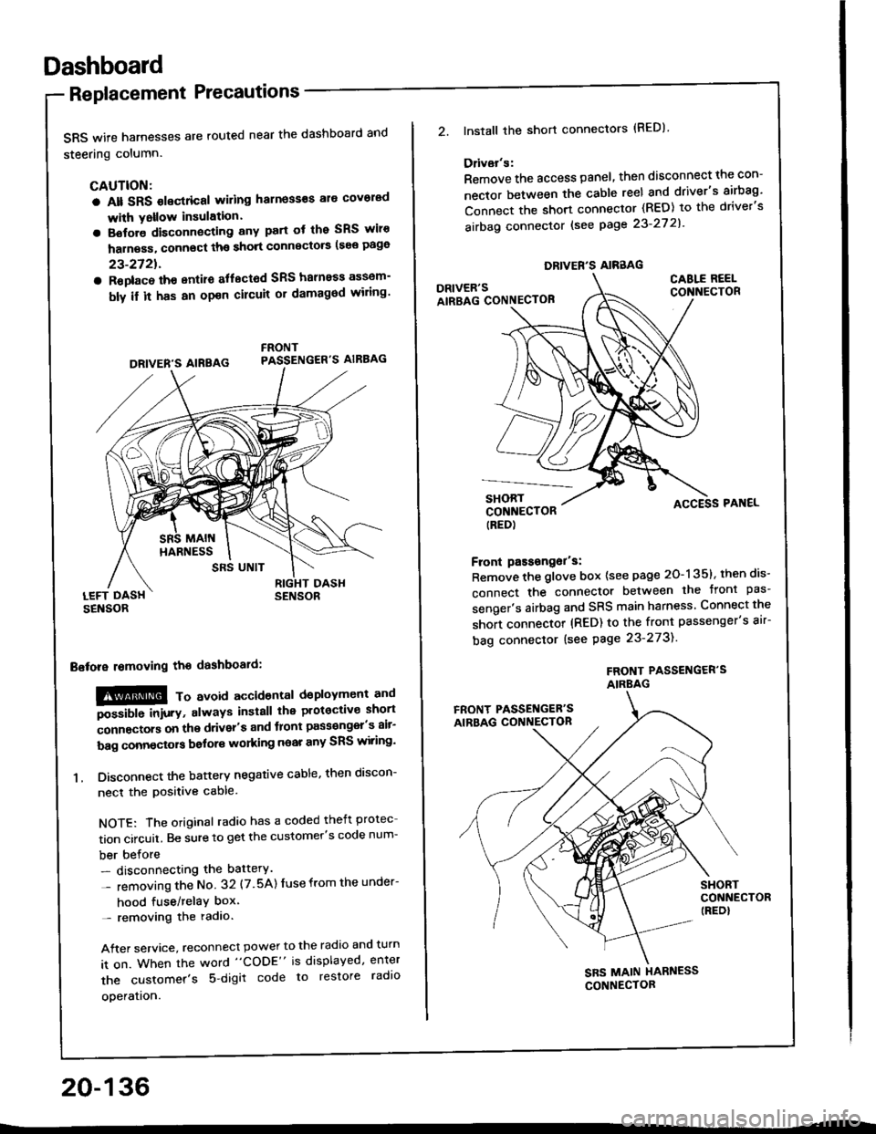
Dashboard
Replacement Precautions
SRS wife harnesses are routed near the dashboard and
steering column.
CAUTION:
a Alt SRS olectrical wiling harness€s ale covorad
with Yollow insulation.
a Botore disconnecting any part ot the SRS wiro
harness, connect ths short connscto6 (see page
23-2721.
a Roplac6 ih€ entiro aflectod SRS halnoss assem-
bly il it has an opon cilcuit or damagod wiling'
LEFT DASHSENSOR
Bstora lomoving the dashboaid:
!@@ To avord accioenlal dsployment and
""iUU inir.v, always install the plotoctive short
;onnectors on the driver's and tlont pass€ngel's air-
bag connectors bolors working near any SRS wiring'
1. Disconnect the battery negative cable, then discon-
necl the positive cable.
NOTE: The original radio has a coded theft protec
tion circuit. Be sure to get the customer's code num-
ber before- disconnecting the battery.
- removing the No 32 (7.5A) Iuse from the under-
hood fuse/relaY box'- removing the radio.
After service, reconnect power to the radio and turn
it on. When the word "CODE" is displayed, enter
the customer's 5 digit code to restore radlo
ooeration.
DRIVER'S AIREAG
SRS UNIT
20-136
DRIVER'S AIRBAG
2.lnstall the short connectors (RED)
Ddvar's:
Remove the access panel, then disconnect the con-
nector between the cable reel and driver's airbag'
Connect the short connector (RED) to the driver's
airbag connector lsee page 23-27 2l'
DRIVER'SAIRBAG CONNECTOB
CABLE REELCONNECTOR
SHORTCONNECTOR(RED)
Front passongor's:
Remove the glove box {see page 20-135}, then dis-
connect the connector between the tront pas'
senger's airbag and SRS main harness Connect the
short connector (RED) to the front passenger's air-
bag connector (see Page 23-273).
FROf{T PASSENGER'SAIRBAG
ACCESS PAI{EL
FRONT PASSET{GER'SAIRBAG CONNECTON
SHORTCONNECTOR(REDI
SBS MAIN HARNESS
CONNECTOR
Page 1039 of 1413
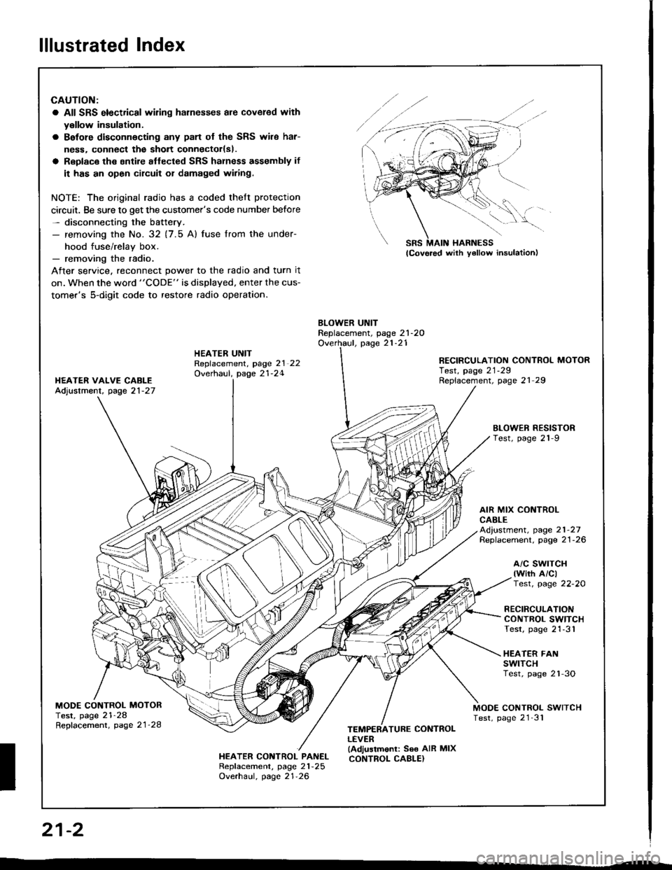
lllustrated Index
CAUTION:
a All SRS electrical wiling harnesses are covered with
y€llow insulation.
a Bafore disconnecting any pan of the SRS wile har-
ness. connect the sholt connectorlsl.
a Replace the sntire aflected SRS halness assembly if
it has an open circuit or damaged wiring.
NOTE: The original radio has a coded thelt protection
circuit. Be sure to get the customer's code number before- disconnecting the battery.- removing the No. 32 (7.5 Al fuse lrom the under-
hood fuse/relav box.- removing the radio.
After service, reconnect power to the radio and turn it
on. when the word "CODE" is displayed, enter the cus-
tomer's 5-digit code to restore radio operation.
BLOWER UNITReplacement, page 21-2OOverhaul, page 21-21HEATER UNITRepfacement, page 2l 22Overhaul, page 21-24
RECIRCULATION CONTROL MOTORTest, page 21-29Replacement, page 21 29I{EATER VAIVE CABLEAdjustment, page 21-27
BLOWEN RESISTORTest, page 21-9
AIR MIX CONTROLCABLEAd,ustment, page 21-27Replacement. page 21-26
a/c swrTcH(wirh A/clTest, page 22-20
RECIRCULATIONCONTROL SWITCHTest, page 21-31
HEATER FANswtTcHTest, page 2'l-3O
MODE CONTROL MOTORTest, page 21-28Repfacement, page 21'28
MODE CONTROL SWITCHTest, page 21'31
HEATER CONTROL PANELRepf acement, page 21 -25
Overhaul, page 21-26
TEMPERATURE CONTROLLEVER(Adjustmonl: See AIR MIXCONTROL CABLE}
SRS MAIN HARNESS
W,
21-2
I
Page 1059 of 1413
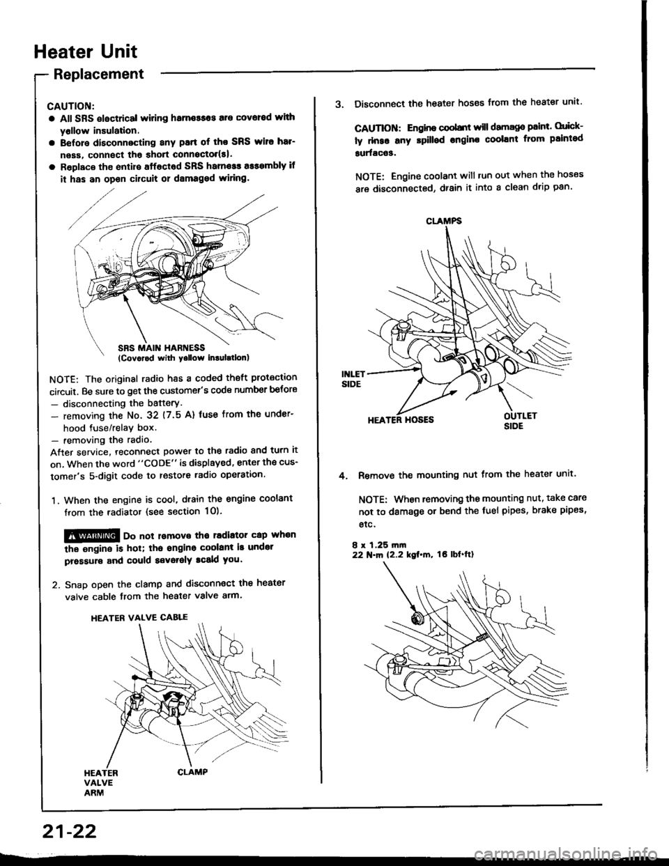
Heater Unit
Replacement
CAUTION:
a All SRS electrical witing hame$os are covoed wlth
yollow insulation.
a Before disconnecting any patt of tho SRS wito har-
neas, connect tha shott connoctol(s|.
a Roplaco th€ enlire sffacted SRS harnosr a$smbly if
it has an opon cilcult or dsmaged wiring.
NOTE: The original radio h8s a coded theft protection
circuit. Be sure to get the customer's code number betors
- disconnecting the bafterY.
- removing the No. 32 (7.5 A) fuse from th€ under-
hood tuse/relav box.- removing the radio
After service. teconnect power to the radio and turn it
on, when the word "CODE" is displayed, enter the cus-
tomer's 5-digit code to restore radio operation.
1. When the engine is cool, dtain the engine coolant
from the radiator (see section 1O).
@@ oo not lomove tho radiator cap whan
the ongine is hol; tha ongino coolant is undot
pressure and could a€voralY tcald you.
2. Snap open the clamp and disconnect the heater
valve cable from the heater valve arm.
HEATER VALVE CABLE
21-22
CLAMFS
3. Disconnect the heater hoses from the heater unit'
CAUTIOII: Engino coobnt will damago paint. orick-
ly dnse any rpilled engine coolant from paintod
surfac63.
NOTE: Engine coolant will tun out when the hoses
are disconnected, drain it into a clean drip pan'
HEATER HOSES
Remove the mounting nut from the heater unit.
NOTE: When removing the mounting nut, take care
not to damage or bend the fuel pipes, brake pipes,
etc.
8 r 1,25 rn|n22 N.m 12.2 kgt.m, tO lbf'ftl
4.
Page 1071 of 1413
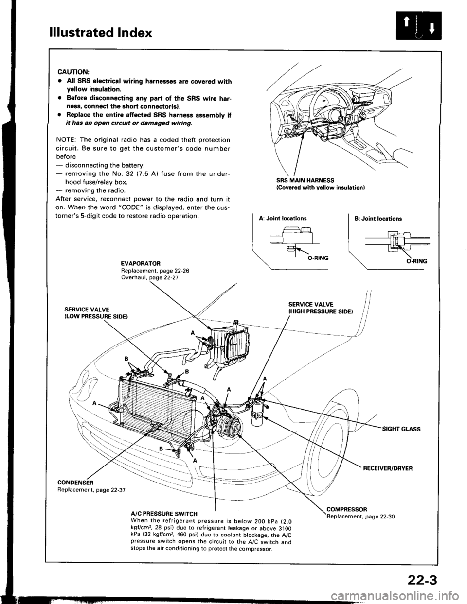
lllustrated Index
CAUTION:
. All SRS electrical wiring harnossos are cover€d withyellow insulation.
. B€fors disconnacting any part of the SRS wire har-ness, connsct the 3hort connsctor(s).. Replace the entirs affscted SRS harness assembly itit has an open circuit or damaged wiring.
NOTE; The original radio has a coded theft protection
circuit. Be sure to get the customer's code number
before- disconnecting the battery.- removing the No.32 (7.5 A) fuse from the under-
hood fuse/relay box.- removing the radio.
After service, reconnect Dower to the radio and turn it
on. When the word "CODE" is displayed, enter the cus-
tomer's 5-digit code to restore radio operation.
SRS MAIN HARNESSlcover€d with yellow insulationl
EVAPORATORReplacement, page 22-26Ovethaul. Oase 22.27
SERVICE VALVE(LOW PRESSURE SIDEI
SERVICE VALVEIHIGH PRESSURE SIDE)
RECEIVER/DRYER
CONDENSERReplacement, page 22,37
A/C PRESSURE SWITCHCOMPRESSORReplacement, page 22-30When the refrigerant pressure is below 200 kpa (2.0kqflcm,,28 psi) due to refrigerant leakage or above 3]OOkPa (32 kgf/cm,, 460 psi) due to coolant btockage, the A,/Cpressure switch opens the circuit to the A"/C switch andstops the air conditionang to protect the compressor.
22-3
Page 1072 of 1413
Wiring/Connector Locations
A/C DIODECONNECTOR(Loc.ted .bovo tho.ight kick p.n.ll
RADIA'OR FAN RELAY{Localed in the undel-hood fu3o/reltY box)
A/CTHERMOSTAT CONDENSERFANCONNECTOR CONNECTOR
MAIN WIRE HARNESS
A/C WIRE HARNESSCONNECTOR
RADIATOR FANCONNECTOR
A/C WIRE HARNESS
COMPRESSOR CLUTCHCONNECTORA/C PR€SSURE SWTTCHCONNECTOR
22-4
Page 1094 of 1413
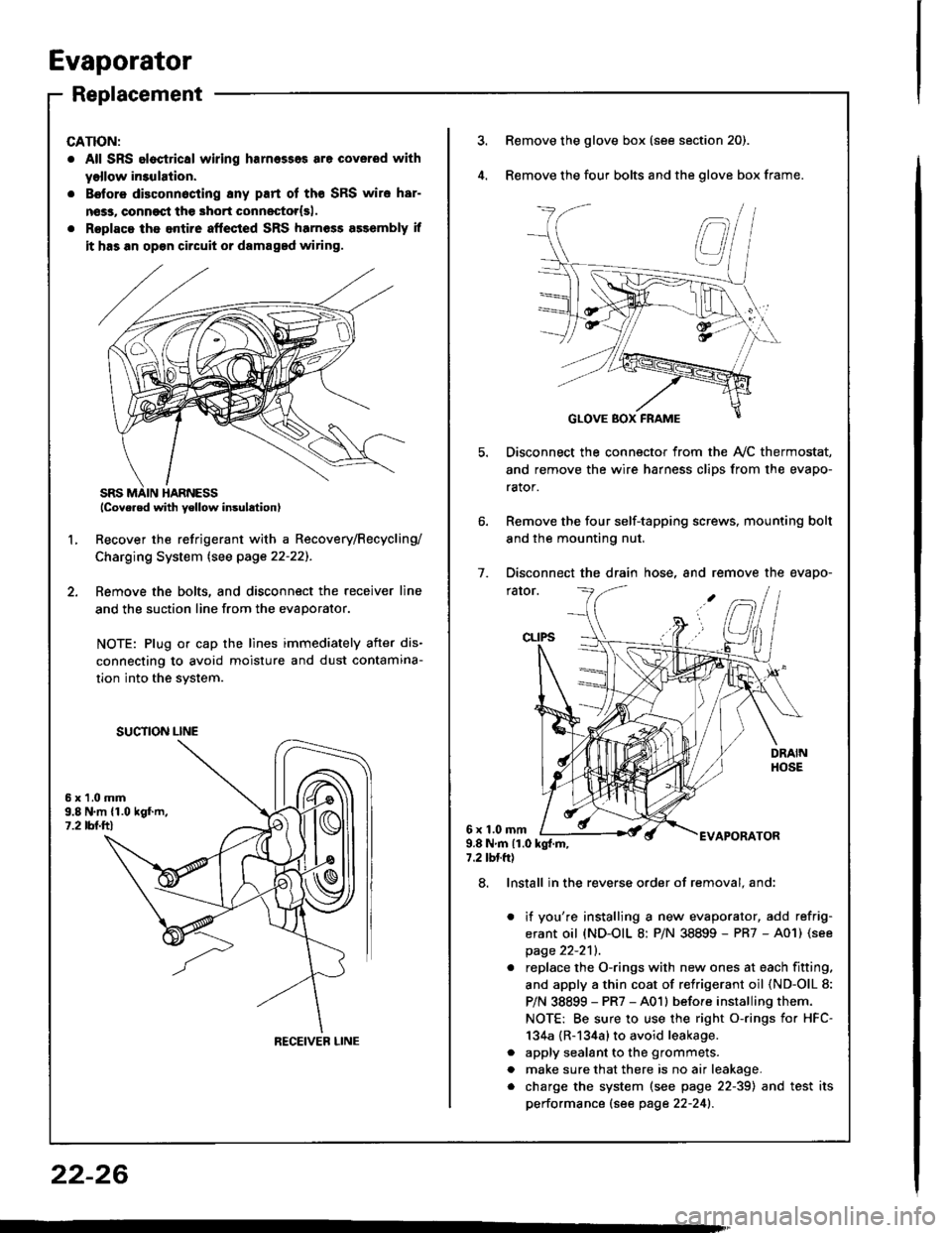
Evaporator
Replacement
CATION:
. All SRS eloctrical wiring harnesses are coverod with
yollow in3ulation.
. B€tore disconnocting 8ny part of tho SRS wire har-
nsss, conngqt th€ 3hort connestor{sl.
. Roplaca ths entire aftected SRS harness a$embly if
it has an op€n circuit or damaged wiring.
lcove.ed with yellow insulation)
Recover the refrigerant with a Recovery/Recycling/
Charging System lsee page 22-22]-.
Femove the bolts, and disconnect the receiver line
and the suction line from the evaporator.
NOTE: Plug or cap the lines immediately after dis-
connecting to avoid moisture and dust contamina-
tion into the svstem.
2.
L
6x1.0mm9.8 N.m {1.019f.m,1.2 tbl.ttl
SUCTION LINE
RECEIVEB LINE
3.Remove the glove box (see section 20).
Remove the four bolts and the glove box frame.
Disconnect the connector from the Ay'C thermostat,
and remove the wire harness clips from the evapo-
rator.
Remove the four self-tapping screws, mounting bolt
and the mounting nut.
Disconnect the drain hose, and remove the evapo-
rator.
1.
6x1.0mmAPORATOR9.8Nm{1.0kg{.m,7.2 tbtft)
a
a
8. Install in the reverse order of removal. and:
it you're installing a new evaporator, add refrig-
erant oil (ND-OIL 8: P/N 38899 - PR7 - A01) (see
page 22-2'll.
replace the O-rings with new ones at each fitting.
and apply a thin coat of refrigerant oil (ND-OlL 8:
P/N 38899 - PR7 - A01l before installing them.
NOTE: Be sure to use the right o-rings for HFC-
134a {R-134a} to avoid leakage.
apply sealant to the grommets.
make sure that there is no air leakage.
charge the system (see page 22-39) and test its
performance (see page 22-241.
22-26