Page 917 of 1413

Doors
Position Adjustment
NOTE: Place the vehicle on a tirm, level surface when
adjusting the doors.
After installing the door, check for a flush fit with the
body, then check for equalgaps between the front, rear,
and bottom door edges and the body.
The door and body edges should also be parallel. Adiust
at the hinges as shown.
CAUTION: Plac€ a shop towsl on tho jack to pre-
vent damage to the door when loosening the dool
and hingo mounting bolts for adjustmont.
DOOR MOUNTING BOLTS8 x 1.25 mm 29 N.m l3.O kgl m, 22lbf trlLoosen lhe door mo!nting boltsslightly to move the door lN or OUTuntil ir's flush wath the body. Itnecessary, you can install a shim be-hind one hinge to make the door
edges PAFALLEL with the body.
HIIGE xrruce MouNTTNG BoLTs
I x 1.25 mm29 N.m l3.O kgt'm,22 lbl'ft)Loosen the hinge mounting
bolts, and move the doorBACKWARD oI FORWARD,
UP or DOWN as necessaryto equalize the gaps.
Lower the glass,
SHOP TOWEL
NOTE: Check tor water leaks.
DOOR
The door and body edges should be parallel.
Striker Adjustment
Make sure the door latches securely without slamming.
lf it needs adjustment;
1.Draw a line around the st.iker for reJerence.
Loosen the screws, and move the striker lN or OUT
to make the latch tit tighter or looser. Move the strik-
er UP or DOWN to align it with the latch opening.
Then liqhtly tighten the screws and recheck.
scREwsI x 1.25 mm18 N.m ('1.8 kgt.m, 13lbf.ttl
NOTE: Hold rhe outer handle out, and push the door
against the body to be sure the striker allows a flush
fit.
lf the door latches properly, tighten the screws and
recheck.
20-48
;dlHffi
Page 960 of 1413
Interior Trim
Replacement
a W€al gloves to remove and installth€ trim and panols.a When prying with a flat tip screwd.ivor. wrap it withprotective tap€ to prevent damaga.
NOTE: Take care not to bend or scratch the trim andDanels.
Kick panel/Front pillar trim removal:
l. Remove the kick Danel.
< : Clip locations
A< | Cllp, 1 B< : Ctip, 1 CV : C[p, 1
Jtl,Ml*
U ry-ry
NOTE: Remove the driver's kick panel while pullingthe hood release handle.
KICK PANEL
Pull the door trim back, then remove the front oillarrflm.
< : Clip locations, 4
lnstallation is the reverse of the removal procedure.
NOTE: lf necessary, .eplace any damaged clips.
FRONT PILLAR
20-91
Hatchback
Rear trim panet/Side trim panel/Ouarter pillar trim p-l16moval:
1. Open the hatch.
2. Remove the .ear shelt.
Remove the rear seat (see page 20-'l08).
Remove the trunk mat and spare tire lid.4.
ao..t dr
REAR SHELF
REAR SHELF
TRUNK MAT
SPARE TIRE LID
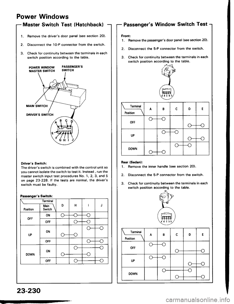
Page 1336 of 1413

1.Remove the drivef's door panel (see section 201.
Oisconnect the 1O-P connector from the switch.
Check tor continuity between the terminals in each
switch position according to the table.
pOWERWTNDOW PASSENGEB'S
MASTER SWTTCH SWITCH
Drive.'s Switch:
The driver's switch is combined with the control unit so
you cannot isolate the switch to test it. Instead , run the
master switch input test procedures No. 1, 2, 3, and 5
on page 23-228, lf the tests are normal, the d.ivet's
switch must be faultv.
i1\i
\4r-I^l,r
)rvti\
.Fi'ilj
Passengsl'r Switch:
Te.minsl
DHJI Msin \Position I Switch \
OFFONo-(J--o
OFFo--o
UPONo---o
o--
OFFo--o
DOWNONo-
o--o
--o
OFFo--o
Power Windows
Master Switch Test (HatchbacklPassenger's Window Switch Test
23-230
Front:
1 . Remove the passenger's door panel {see section 20).
2. Disconnect the 5-P connector from the switch.
3. Check for continuity between the terminals in each
switch position sccording to the table.
Rear (Sedanl:
1. Remove the inn€r handle (see section 2O)'
2, Disconnect the 5-P connector from the switch.
3. Check for continuity between the terminals in each
switch position according to the table.
Torminal
il;_\
ARD
OFFo-
--o
UPo---o
G_--o
DOWr.lo---o
Terminal
;;__\ID
OFFG_--o
o---o
UPG_--o
o---o
DOWNo---o
o-
Page 1337 of 1413
Master Switch ReplacementPassenger's Window Switch
Hatchback:
1. Remove the driver's door panel (see section 20).
2. Disconnect the 1O-P connector lrom the switch,
3, Remove the three mounting screws and the switch.
Sedan:
1. Remove the driver's door panel (see section 2O).
2. Disconnect the 1 6-P and 1-P connectors from the
switch.
3. Remove the two mounting screws and the switch.
POWER MIRRORswtTcH
scREws
Replacement
Flont:
1 . Remove the passenger's door panel (see section 201.
2. Disconnect the 5-P connector from the switch.
3. Remove the two mounting screws and the switch.
Roar (S6danl:
1. Remove the inner handle (see section 20).
2. Disconnect the 5-P connector from the switch.
3. Remove the two mounting screws and the switch.
w|I{Dow.swtTcH
swtTcl{
INNER HANDLE
23-231
Page 1347 of 1413
Door Lock Switch Test
1. Remove the inside handle.
Disconnect the 3-P connector from the switch.
Check for continuity between the terminals in eachswitch position according to the table.
termtnal
Position \
nc
LOCKoo
OFF
UNLOCKo
ff
23-241