Page 555 of 1413

7.Remove the transmission jack.
Attach the torque converter to the drive plate with
eight bolts and torque:
Rotate the crankshatt as necessary to tighten the
bolts to 1/2 of the specilied torque, then to the final
toaque, rn a cnsscross pattern.
After tighten the last bolts, check that the crankshaft
rotates freely.
TOROUE: 12 N.m {1.2 kgl.m.8.7 lbf.ft}
Install the torque converte. cove. and engine
stiffener.
L
9.
6 r 1.O mm12 N.m 11.2 kgt.m, 8.7 lbl.ltl
10.
12 N.m 11.2 kgf.m,8.7 rbt.ft)
Tighten the crankshaft pulley bolt to specified
rorque.
TOROUE: 177 N.m {18.O kgt.m, 130 lbf'ft}
10 x 1.25 mm44 N'm {4.5 kgf.m.33 rbt'frl
8 x '1.25 mm24 N.m (2.4 kgl.m,17 tbf.trl
lO x '1.25 mm43 N.m14.4 kgf.m, 32 lbf.ltl
11. Connect the ATF cooler hoses to the joint pipes.
12. Connect the throttle control cable to the throttle con-
trol lever and install the right front mount/bracket.
THROTTLE CONTROL LEVERTHROTTLE CONTROLCABLE END
JOINT PIPES
12 x 1 .25 mm64 N.m {6.5 kgf.m,47 tbf.ftlReplace.
ATF COOLER HOSES10 x 1.25 mm RIGHT44 N.m (4.5 kgf'm, FRONT33 rbl.ftl MoUNT/BRACK€T
t5.Install the control lever with a new lock washer to
the control shalt. then install the shift cable cover.
CAUTION: Take care not to bend the shift cable.
CONTROLSHAFT
SHIFT CABLE
CONTROL LEVER
6 x 1.0 mm12 N.m{1.2 kgf.m,8.7 lbl.rr)
SHIFT CABLECOVER
LOCK6 x 1.0 mm14 N.m 11.4 kgl.m,10 lbf.fr)
(cont'dl
Replace.ASHER
14-165
Page 611 of 1413
System Description
Fluid Flow Diagram
The system is a compact rotary-valvs-type power stssring, connocted to the st€oring gearbox. Th6 fluid pressure is pro-vided by a vane-type pump which is driven by the engine crank pulley. The amount of fluid and pressurs is regulsted bythe flow control valve built into ths pump, The fluid prssaurs from th6 pump is dolivsred to tho valve unit sround the pin-ion of the steering g€arbox. The vslv€ inside the valvs unit controls the hydraulic prossur€ End changos the direction otthe flow. The fluid then flows to the power cylinder, where rack thrust is gen6rat6d. Fluid returning from th6 powsr cylin-der flows back to the .eservoir, where the fluid is 'filtered" and supplied to the pump Egain.
17-4
Page 612 of 1413

Construetion
The pump is a vane-type incorporating a flow control valve (with an integrated relief valve) and is driven by a V-belt from
the crank pulley. The pump features 10 vanes, Each vane performs two intake/dischsrge operations for every rotation of
the rotor. This means that the hydraulic fluid pressure pulse becomes extremely small during discharge.
CAM RING
FLOW CONTBOL VALVE
DRIVE
Operation
The belt-driven pulley rotates the rotor through the drive shaft, As the rotor rotates, the hydraulic pressure is applied to
the vane chamber of the rotor and the vanes witl rotate while being pushed onto the inner circumference of the cam .ing.
The inner circumference of the cam ring has an extonded portion with respect to the center of the shaft. so the rollers
move downward in the axial direction as the carrier rotates. As a result of this roller movemsnt, the internal volume of the
vane chamber will change, resulting in fluid intake and discharge.
START OF FLUID INTAKE:FLUID INTAKE:FLUID MOVEMENT:FLUID DISCHABGE:
DISCHARGE P('BT
I
SHAF'
The vanes are pushed ontothe inner circumference of th6cam ring.
Th6 volums otth€ van€ cham-ber increasos so that lluid issuckod in.
Th6 sucked-in fluid moves
towsrd the discha196 pon.As the vanes return to th€their original position on theinner side, the volume of thevane chamber decreases sothe fiuid is discharg6d fromthe discharge port.
(cont'd)
INLET PORT
VANE
Page 627 of 1413

Inspection and Adjustment
Pump Belt
NOTE: When using a new b€li, first adiust the deflection
or t€naion to the values for the new belt, thsn readiust
ths deflection or tension to the values tor the used b€lt
after running sngine for five minutss.
lnspoction
Attach th€ belt tonsion gauge to th6 belt and measure
ths tension of the bslt.
Tanaion:
U3.d Brft: 391, - 5/O N (lO - 55 kgf, 88 - r20 |bf)
Ncw Bch: 7aO - 89, N (75 - 90 kgt, 170 - 20O lbO
NOTE:
. lf thsre are cracks or any damage evident on the belt,
raplaca it with a now ono.
. Follow the manufacturer's insructions for the tonsion
g8uge.
PUII"EY
07JGG - 00r0r0a
Inspect the pump belt for cracks or any damage.
Replace the belt with a new one if nec€ssary.
Mc!3uramrnl without Bch Tcntion Grugr:
Apply a torce of 98 N (10 kgl, 22 lbll and measure ths
deflection between tho power ste€rin9 pump and tho
crankshaft pulleys.
Daffaction:
U:ed Bch: 11.5- 13.5 mm (0.,t5-0.53 inl
Nlw Brh: 8.0 - 10.0 mm (0.31 - 0.39 inl
here,
17-20
Adiu3tmant
1, Loosen the power stesring pump mounting bolts.
2. Turn ths adiusting bolt to gst the propor bolt ten-
sion, then rstighten the bolts.
3, Start ths €ngine and turn the steering wheel trom
lock-tolock s€veral times, then stop the engino and
recheck ths deflection of the belt.
AD'USN G BOLT
Page 1102 of 1413

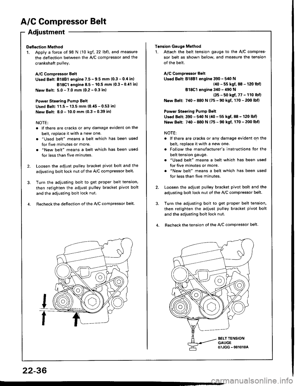
A/C Compressor Belt
Adjustment
Dstlsqtion Method
1. Apply a force of 98 N (10 kgf, 22 lbf), and measure
the deflection between the A,/C compressor and the
crankshaft Dullev.
A/C Compressor Belt
Us€d Eelt: 81881 engine 7.5 - 9.5 mm (0.3 - 0.4 in)
Bl8Cl engine 8.5 - 10.5 mm (0.3 -0.11 inl
New Belt: 5.0 - 7.0 mm (0.2 - 0.3 inl
Power Stesring Pump Belt
Used Beli: 'l1.5 - 13.5 mm (0.,[5 - 0.53 inl
New 8€lt: 8.0 - 10.0 mm (0 3 - 0.39 inl
NOTE:
. lf there are cracks or any damage evident on the
belt, replace it with a new one.
. "Used belt" means a belt which has been used
for five minutes or more.
. "New belt" means a belt which has been used
for less than five minutes.
2. Loosen the adjust pulley bracket pivot bolt and the
adjusting bolt lock nut of the Ay'C compressor belt.
3. Turn the adiusting bolt to get proper belt tension,
then retighten the adjust pulley bracket pivot bolt
and the adjusting bolt lock nut.
4. Recheck the deflection of the lvc compressor belt
22-36
Tonsion Gauge Method
1. Attach the belt tension gauge to the Ay'C compres-
sor belt as shown below, and measure the tension
of the belt.
A/C Compressot Belt
Used 8€lt: Bl8Bl engine 390 - 540 N
(40 - s5 kgf, 88 - 120 lbfl
Bl8Cl ongine 3il0 - il90 N
(35 - s0 kgf, 77 - 110 lbfl
N€w Belt 7,10 - 880 N {75 - 90 kgf, 170-200lbl}
Powor Steoring Pump Belt
Used Belt: 390 - 5,{l N (40 - 55 kgf, 88 - 120 lbll
N6w Bolt: 74O - 880 N 175 - 90 kgf, 170-200lbt)
NOTE:
. lf there are cracks or any damage evident on the
belt, replace it with a new one.
. Follow the manufacturer's instructions for the
belt tension gauge.
. "Used belt" means a belt which has been used
for five minutes or more.
. "New belt" means a belt which has been used
tor less than five minutes,
2. Loosen the adjust pulley bracket pivot bolt and the
adjusting bolt lock nut of the AVC compressor belt.
3, Turn the adjusting bolt to get proper belt tension,
then retighten the adjust pulley bracket pivot bolt
and the adjusting bolt lock nut.
4. Recheck the tension of the A{/C compressor belt.
Page 1214 of 1413

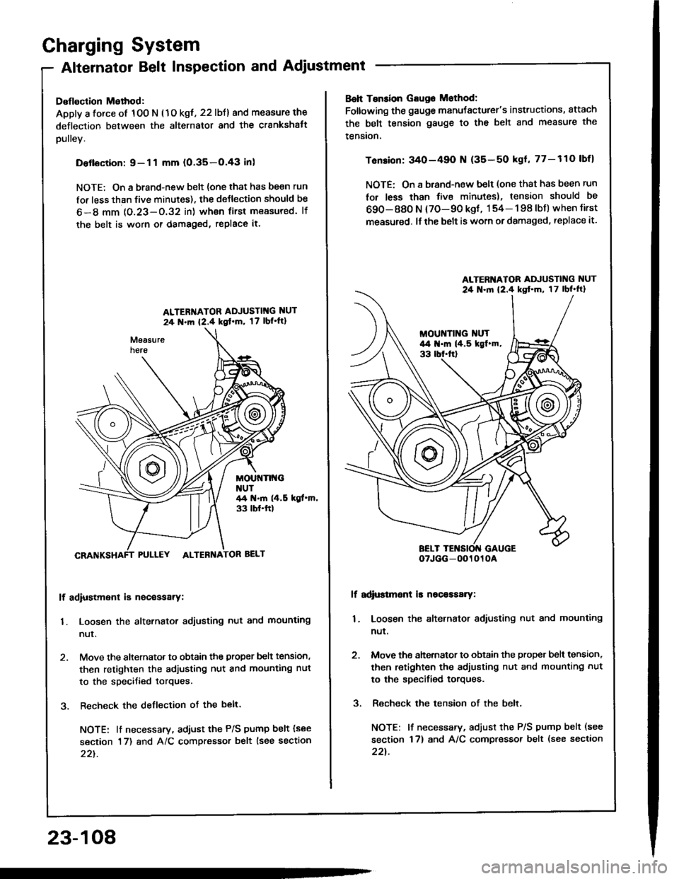
Charging System
Alternator Belt Inspection and Adjustment
Deflection Method:
Apply a force of 100 N (1o kgt, 22 lbJ) and measure the
deflection between the alternator and the crankshatt
pulley.
Detlsction:9-11 mm (0.35-O.43 inl
NOTE; On a brand-new belt {one that has be€n run
for less than five minutes), the deJlection should be
6-8 mm 1O.23-O.32 in) wh€n first measured. lf
the belt is worn or damaged, replace it.
ALTER'{ATOR ADJUSTIT{G NUT
24 N.m {2.4 kgl'm, 17 lbl'ft1
MOUt{Tlt{GNUT44 t{.m (4.5 kgt.m,33 tbf.ft)
PULLEY ALTEBNA
lf adiustment is nocessarY:
1. Loosen the alternator adjusting nut and mounting
nur.
2. Move the alternator to obtain the proper belt tension,
then retighten the adjusting nut and mounting nut
to the specified torques.
3. Recheck the deflection ot the belt.
NOTE: lt necessary, adiust the P/S pump belt (see
section 17) and A/C compressor belt lsee section
22t.
23-108
Boh Tsnsion Gaug6 Mothod:
Foltowing the gauge manuJacturer's instructions, attach
the belt tension gauge to the belt and measure the
tension.
Tension: 340-49O N (35-50 kgl, 77-110 lbfl
NOTE: On a brand-new belt (one that has been run
for less than tive minutes), tension should be
690-880 N (70-90 kgt, 154- 198 lbJ) when tirst
measured. lf the belt is worn or damaged, replace it.
lf adi$tmsnt is nscaasary:
1. Loosen the alternator adiusting nut and mounting
nut.
2. Move ths ahernator to obtain the proper bslt tension,
then retighten the adjusting nut and mounting nut
to the specified torques.
3. Recheck the tension of the belt,
NOTE: lf necessary, adjust the P/S pump belt (see
section 17) and A/C compressor belt (see section
22t.
ALTERI{ATOR ADJUSTING NUT
24 .ln 12.4 kst'm, 17lbl'ft}
oTJGG-0O1010A