1994 HONDA INTEGRA fuse box
[x] Cancel search: fuse boxPage 441 of 1413

CAUTIOI{:
a All SRS eloctdcal wiring harna$os are covcred whh
yollow lnaulation.
a Sofora disconnecting any pan ot tho SRS wirc har'
n6ss, connoct the short connoctots (s€6 pago 23-701.
a Roplacs tho entiro aff.ct d SRS ham6t. rssombly it
ii has an opon circuil or damagcd wlrlng.
lf the inspection to. a particular lailure code requir6s the
use of Test Harness {07LAJ - PT3O1 OA):
1, Remove the left side kick panel on the driver's side(see page 1+84).
2. Connect the wire harness to the Tsst Harness.
and/or connect the Test Harness to the TCM sccord-
ing to the troubleshooting flowchart.
NOTE:
a Only the A and D terminals of the Test Harnsss aro
used for Ay'T troubleshooting.
a Unless otherwise noted, use only the Digital
Multimeter, commerciallv available or KS-AHM-
32{)03, for testing.
c
DIG]TAL MULTIMETERComm€rciallv availableKS-AH M-32-.003,or gouivalEnt
) o o o o o o o o o o ) olo D o o o o o qoo o o o olo o o o o . o o o . c
To.miml Locrtlonr
a TCM Ro3at Procoduro
1 . Tum the ignition switch off.
2. Remove the No. 32 BACK UP fuse {7.5 A} from the
under-hood luse/relay box 'or 10 seconds to reset
the TCM.
NOTE; Disconnocting the No. 32 BACK UP tuse also
cancels ths radio anti-theft code, preset stations and
tho clock sefting. Get the customer's code number
and make note ol the radio presets before removing
the fuss so you can reset them.
a Finll hoc.dulr
NOTE: This procedure must be done after any
troubleshooting.
1 . Removs ths s9ocialtool from the Service Check Con-
noctor.
2. Reset the TCM.
3, S6t th€ radio preset stations and clock setting.
BACK UP (7.5 A} FUSE
14-49
Page 443 of 1413

Number of @indicator light
blinks while
Service Check
Connector is
connected with
the special tool.
@ indicator
lightPossible CauseSymptomRefer to
page
'loBlinksDisconnected engine coolant tempera-
rure (ECT) sensor connector
Short or open in ECT sensor wire
Faulty ECT sensor
Lock-up clutch does not
engage.14-68
1lOFFDisconnected ignition coil connector
Short or open in ignition coil wire
Faulty ignition coil
. Lock-up clutch does not
engage.'t 4-7 0
13Blinks. Shon or open in LT GRN wire between
the D3 terminal and ECM. Faulty barometric pressure {BARO)
sensor
NOTE: The BARO sensor is built into
the ECM
. No specific symptom
appears.
14-7 1
14Blinks. Short of open in FAS {YEL} wire be-
tween the D16 terminal and ECM. Faulty ECM
. Transmission jerks hard
when shitting.
't5OFFDisconnected mainshaft speed sensor
connecror
Short or open in mainshaft speed sen-
sor wire
Faulty mainshaft speed sensor
. Transmission jerks hard
when shifting.
14-75
SymptomProbable CauseRet.page
LQ! indicator light is on steady, not blinking whenever the ignition is on.14-77
[Q3] indicator light does not come on for 2 seconds after ignition is first
turned on.14-78
Lock-up clutch does not have duty operation (ON-OFFI.Check A/C signal with
A/C on.14-80Lock-up clutch does not engage.
Shitt leve. cannot be moved lrom @ position with the brake pedal
depressed.Check brake switch signal,14-41
It the self-diagnosis LQ4 indicator light does not blink, perform an inspection according to the table below.
a lf a customer describes the symptoms for codes 3, (yet the LQ! indicator light is not blinkingl, 6, 1 1 or 15, it will
be necessa.y to recreate the symptom by test driving. and then checking the @ indicator light with the ignition still
oN.
e lt ttre @ indicator light displays codes olher than those listed above or stays lit continuously, the TCM is faulty.. Sometimes the Lqd indicator light and the Malfunction Indicator Lamp (MlL)/Check Engine light may come on simul-taneously. lf so, check the PGM-Fl system according to the numbe. of blinks on the MIL/Check Engine light. thenreset the memory by removing the BACK UP fuse in the unde.-hood fuse/relay box for more than 1O seconds. Drive
the vehicle for several minutes at speed over 30 mph (5O km/h), then recheck the MIL/Check Engine light.
NOTE:
. PGM-FI system
The PGM-Fl system on this model is a sequential multiport fuel injection system.a Disconnecting the BACK UP luse also cancels the radio anti-theft code. preset stations and the clock setting. Get
the fuse so vou can reset them.the customer's code number and make note ot the radio
14-51
Page 608 of 1413

Steering
Special Tools ............. 17-2
Component Location
lndex ................ ...... 17-3
System Description
Ff uid Flow Diagram ......................... 17 -1
Steering Pump ................................. 17-5
Steering Gearbox ............................. 17-7
Troubleshooting
General Troubleshooting ................ 17-10
Noise and Vibration ......................... 17-14
Fluid Leaks ............. 17-16
Inspection and Adiustment
Steoring Operation .......................... 17 -14
Power Assist Check
with Car Parked ........................... 17-18
Steering Linkage and Gearbox ....... 17-19
Pump Beh .............. 17-20
Rack Guide Adjustment ............. ..... 17-21
Ff uid Replacement ...................... ..... 17 -21
Pump Pressure Check .................. .... 17 -22
Ffuid Leakage lnspection ................ 17-23
+ Steering Wheel
Removal ..,,,,,,,........ 17-24
Disassembly/Reassembly ............... 17 -25
fnstallation ,......,,,,,. 17-26
* Steering Column
Removaf .................17-28
Inspection .............. 17-30
Installation ............. 17-31
Power Steering Hoses. Pipes
Replacemont ......... 17-3tl
Power Steering Pump
Removal ................. 17-35
Disassembly .......... 17-35
Reassembly ........... 17-'10
lnstallation ........,..., l7-tltl
Steering Gearbox
Removaf .,.,............. 17-45
Disassembly .......... 17-/E
Reassembly ........... 17-53
lnstallation ............. 17-63
Ball Joint Boot Replacement .......... 17-65
SUPPLEMENTAL RESTRAINT SYSTEM {SRSI
The Integra SRS includes a driver's airbag. located in the steering wheel hub, In addition, all models except the
RS model for Canada have a front passenger's airbag located in the dashboard above the glove box. Information
necessarv to safely service the SRS is included in this Service Manual. ltems marked with an asterisk {') on the
contents page include, or are located near, SRS components. Servicing. disassembling or replacing these items
will require special precautions and tools, and should therefore be done by an authorized Acura dealer.
a To avoid rsndering ths SRS inoporative, which could load to po.sonal iniury 01 d€ath in th€ event ot a ssvare
lrontal collision, all SRS service work muat be performod by an authorizod Acura deal6t.
a lmploper service procodules. including incorloct romoval and installation of the SRS, could lead to personal iniu-
ry caused by unintontional activation ot the airbags.
a All SRS elsctdcal wiring harnesses ara covorod with ysllow insulation. Rolalod compon€nts 8re locatsd in tho
stse ng column, tront console, dashboard, and dashboard lower panel, and in the dashboard above the glove
box. Do not use oloctrical tost equipmoni on thosa cilcuits.
NOTE: The original radio has a coded thett protection circuit. Be sure to get the customer's code number before
- disconnecting the battery.- removing the No. 32 (7.5 A) tuse from the under-hood fuse/relay box.
- removing the radio.
Alter service, reconnect power to the radio and turn it on. When the word "CODE" is displayed' enter the cus-
tomer's 5-digit code to restore radio operation.
Page 636 of 1413

8. Remov€ the stesring ioint cover.
Remove tho steering joint bolts, and move the ioint
toward ths column.
JOIMT OOVER
STEERING COLUMN
BOITS
10.
'l1.
Disconnoct the ignition switch connectors from th6
undor-dash fuse/relav box.
Remove tho steering column by removing the
attaching nuts 8nd bolts.
17-29
Page 640 of 1413

7.
Connect the ignition switch wire connectors to the
under-dash fuse/relav box.
Install the combination switch and turn signal can-
celing sleeve onto the steering column.
NOTE: Be sure the wires are not caught or pinched
by any parts when installing the combination
switch.
TURN SIGNAL CANCELINGSLEEVE
Install the cable reel onto the steering column, then
connect the SRS main harness and cable reel wiro
harness and install the connector holder.
NOTE: Align the slot in the cable reel with the pro-
jection on the canceling sleeve.
coMatNATroN swncH
UPPER COLUMN COVER
9. Installthe column covers.
scREws
lnstall the driver's knee bolster.
lnstall the lower cover.
Installthe steering wheel {see page '17-26).
10.
11.
't2.
17-33
Page 1001 of 1413

Dashboard
Component Removal/lnstallation (cont'dl
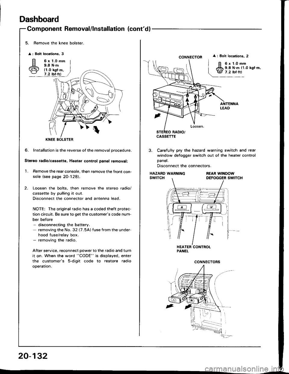
5. Remove the knee bolster.
: Bolt locations, 3
fi 6rt.omm
6 i;i'i#.,7.2 tbr.ftl
?
KNEE
6. Installation is the reverse of the removal Drocedure.
Stol€o radio/cassette, Heater control panal removal:
1 . Remove the rear console, then remove the front con-
sole (see page 20-128).
Loosen the bolts, then remove the stereo radio/
cassette by pulling it out.
Disconnect the connector and antenna lead.
NOTE: The original radio has a coded theft protec-
tion circuit, Be sure to get the customer's code num-
ber belore- disconnecting the battery.
removing the No. 32 17.5A) fuse from the under-
hood fuse/relay box.- removing the radio.
After service, reconnect power to the radio and turn
i1 on. When the word "CODE" is displayed. enter
the customer's 5-digit code to restore radio
operation.
20-132
CONNECTOR
CASSETTE
i Bolt locations. 2
6 x 1.0 mm9.8 N.m {1.0 kgl.m,
3, Carefully pry the hazard warning switch and rear
window defogger switch out of the heater control
Daner.
Disconnect the connectors.
HAZARD WARNINGswtTcHREAR WINOOWDEFOGGER SWITCH
Page 1005 of 1413

Dashboard
Replacement Precautions
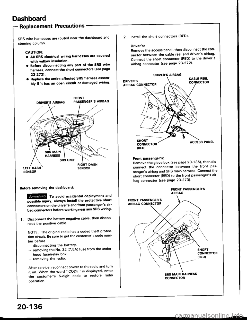
SRS wife harnesses are routed near the dashboard and
steering column.
CAUTION:
a Alt SRS olectrical wiling harness€s ale covorad
with Yollow insulation.
a Botore disconnecting any part ot the SRS wiro
harness, connect ths short connscto6 (see page
23-2721.
a Roplac6 ih€ entiro aflectod SRS halnoss assem-
bly il it has an opon cilcuit or damagod wiling'
LEFT DASHSENSOR
Bstora lomoving the dashboaid:
!@@ To avord accioenlal dsployment and
""iUU inir.v, always install the plotoctive short
;onnectors on the driver's and tlont pass€ngel's air-
bag connectors bolors working near any SRS wiring'
1. Disconnect the battery negative cable, then discon-
necl the positive cable.
NOTE: The original radio has a coded theft protec
tion circuit. Be sure to get the customer's code num-
ber before- disconnecting the battery.
- removing the No 32 (7.5A) Iuse from the under-
hood fuse/relaY box'- removing the radio.
After service, reconnect power to the radio and turn
it on. When the word "CODE" is displayed, enter
the customer's 5 digit code to restore radlo
ooeration.
DRIVER'S AIREAG
SRS UNIT
20-136
DRIVER'S AIRBAG
2.lnstall the short connectors (RED)
Ddvar's:
Remove the access panel, then disconnect the con-
nector between the cable reel and driver's airbag'
Connect the short connector (RED) to the driver's
airbag connector lsee page 23-27 2l'
DRIVER'SAIRBAG CONNECTOB
CABLE REELCONNECTOR
SHORTCONNECTOR(RED)
Front passongor's:
Remove the glove box {see page 20-135}, then dis-
connect the connector between the tront pas'
senger's airbag and SRS main harness Connect the
short connector (RED) to the front passenger's air-
bag connector (see Page 23-273).
FROf{T PASSENGER'SAIRBAG
ACCESS PAI{EL
FRONT PASSET{GER'SAIRBAG CONNECTON
SHORTCONNECTOR(REDI
SBS MAIN HARNESS
CONNECTOR
Page 1007 of 1413

Dashboard
Replacement (cont'd)
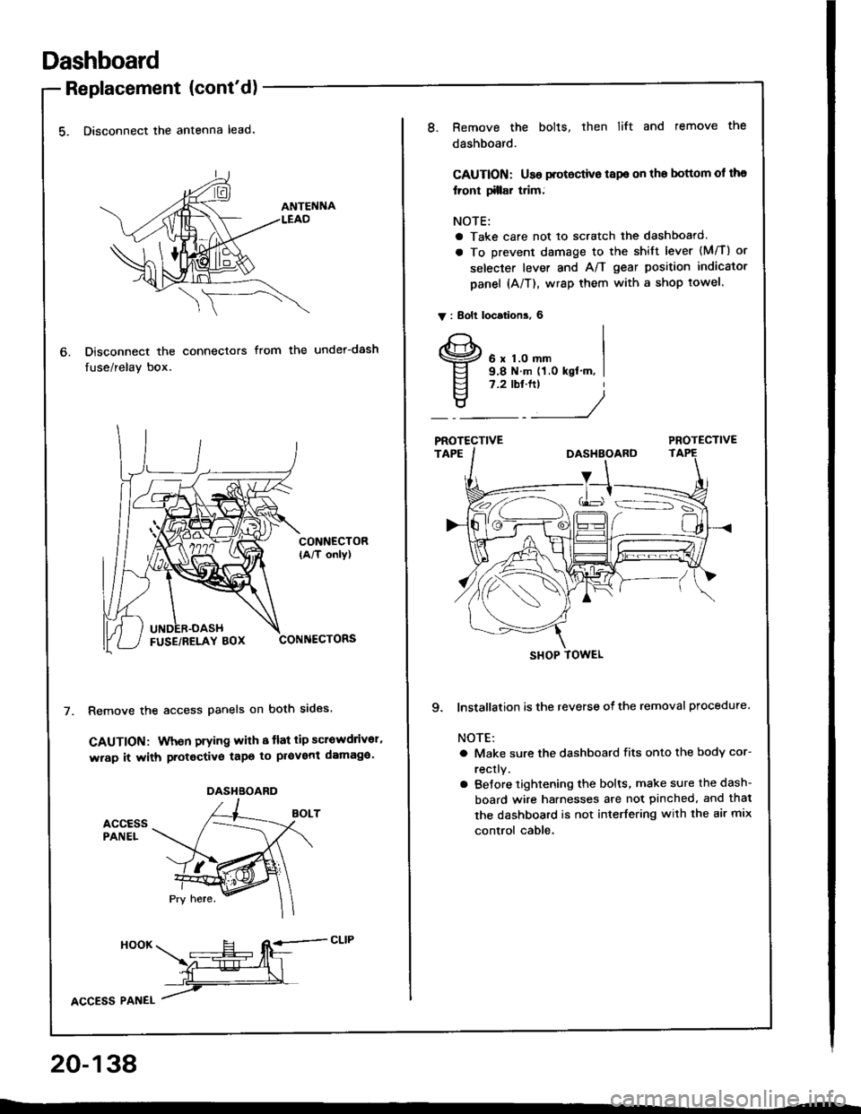
5. Disconnect the antenna lead.
Disconnect the connectors
fuse/relay box.
from the under-dash
CONNECTOR(A/T only)
CONNECTORS
Remove the access panels on both sides.
GAUTION: When prying with 8 tlat tip scrowdrivor'
wrap it with protective tapo to pl€vent damaga'
accEssPANEL
6.
DASHBOARD
HooK ___E-- RE=-cLrP
ffiL
lcCesS Plnel /
20-138
8.Remove the bolts, then lift and remove the
dashboard.
CAUTION: Use protoctive tspe on the bottom ol tha
lront tillar trim;
NOTE:
a Take care not to scratch the dashboard.
a To prevent damage to the shift lever (M/T) or
selecter lever and A/T gear position indicator
panel (A/T), wrap them with a shop towel.
V : Bolt locations, 6
6 x 1.0 mm9.8 N.m (1.0 kgt'm, I7.2 tbt.ftt
____/
PROTECTIVE
9. lnstallation is the reverse of the removal procedure
NOTE:
a Make sure the dashboard fits onto the body cor-
rectly.
a Before tightening the bolts, make sure the dash-
board wire harnesses are not pinched, and thal
the dashboard is not interfering with the air mix
control cable.
SHOP TOWEL