Page 1361 of 1413
Circuit Diagram
UNOER- DASHFUSE/RELAY BOX
WHT/ll-X -FWHr
GRX/4X
WII{DSHI€ID WIPERAIVASHER S1VITCH
REAR WINOOWWIPER MOTOR
BLK
{
G30l
REARwtN00wWASHERMOTOR
BLK
G20'IG401
l*_(ittwA!
Y
Mor
|-8LK
I
G30l
UNOER - HOOO FUSENEUY 8OX
si 4.t,,1 /'i;",ry)"'.,
REARWINOOWWIPER/WASHERswtTcH
8LK
G503
8tK
G20rG101
23-255
. : whh comtinad wchar-wllbr olrnlirn
,r-
Page 1372 of 1413
Supplemental Restraint System (SRS)
Component Locirtion Index
UNDER.DASHFUSE/RELAY BOX
SRS INDICATOR LIGHT(ln th6 gaug6 assembly)Troubleshooting, page 23-276Gauge assembly, page 23-113
CABLE REELReplacement,page 23-301
AIRBAGBeplacement, page 23.295
SRS UNIT (lncluding cowl sensorl
SRS MAIN HARNESS-FRONT PASSENGER'S AIREAGBRANCH lExc€pt Caned. RS modol)
To CRUISE CONTROLSET/RESUME SWITCH
RIGHT DASH SENSORReplacement, page 23-305
FRONT PASSENGER'SAIRBAGlExcept Canads RS model)Replacement, page 23-295Disposal, page 23'299
LEFT DASH SENSORReplacement, page 23-305
23-266
Replacement, page 23-307
Page 1374 of 1413
SRS INOICATOF CIRCUITlln lh6 grugo .$.mblyl
IIIInI llI tltUI
SADH
o
@
o
@
@
a
a
@
a
@
a
@
@
@
a
a
Gircuit Diagram (With Front Passenger's Airbagl
UNOE8- DASHFUSSRELAY BOX
DRIVER'SAIREAGINFI.A]OR
FROI.ITPASSENGER'SAIREAGINFLATOR
UNDERHOODFUSE/REI.AY80x
SRS UNIT l8-P COI'INECTOR
23-269
Page 1375 of 1413
Supplemental Restraint System (SRSI
Wiring Locations
CAUnON: Make sure all SRS ground locrtion3 lrc clrln rnd ground3 tra |.curalv rltachad.
NOTE:
o Alt SRS electricsl wiring harnesses are covered with ysllow insulation.
. RsDlace the entire affected SRS harness assembly if it has an open circuit or damaged wiring.
CABIE REEL to DdrrEFS AnaAC3+ OOI{iECTOR
DASHBOARD WIRE HARNEi9to INDICATOB UGHT in GAUGE ASSEMBLY
5-P CONNECTOBaFs irA[t H^RiEssto FROiIT PASSEMIEFS Ana G3t coftf'Eclon
SRS MAIN HARNESS tO
MAIN WIRE HARNESS+P OONNECTOR
C. b Ra nod.ll
SnS Alt{ ll^ntc8s too sH SErson2+ OOt{tlEcT()R
SRS MAIN HARNESSto UNDER-DASHFUSE/RELAY BOX2"P @NNECTOR
MAIN WIRE HARNESSto DASHBOARD WIREHARNESSlGP CONNECTOR
SBS MAIN HARNESS toLEFT DASH SENSOR2.P CONNECTOA
23-270
Page 1378 of 1413
Front Pas3enger's Side:
. Remove the glove box damper (see section 20), and
then remove the glove box.
. Disconnect the 3-P connector between the front oas-
senger's airbag and the SRS main harness, then con-
nect the short connector (RED) to the airbag side of
the connector.
SHORT CONNECTOR(REDI
SRS MAIN HARNESS
b,
Disconnecting the SRS Connector at the
Under-dash Fuse/relay Box:
CAUTION: Avoid br.aking the connoctor; it's doubte-
locksd.
1. First lift the connector lid with a thin screwdriver,
then press the connector tab down and pull the con-neclor out.
CONNECTORt_tD
To reinstall the connector. push it into position untilit clicks, then close its lid.
23-273
Page 1383 of 1413

Supplemental Restraint System (SRS)
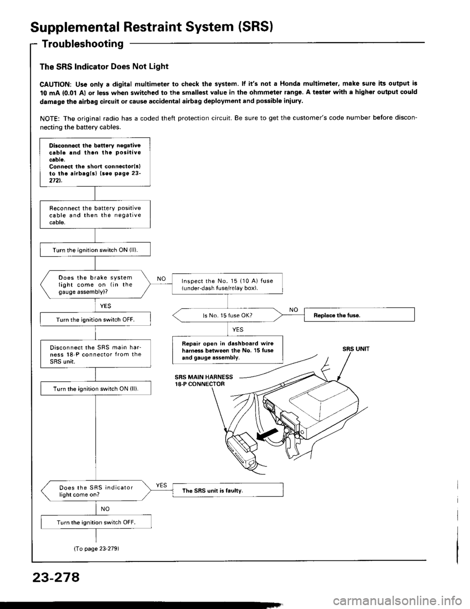
Troubleshooting
The SRS Indicator Does Not Light
CAUTION: Uss only a digital multimeter to check the system. lf it's not a Honda multimeter, make sure its output is
10 mA {0.01 Al or less when switched to the smallest value in the ohmmeter rang€. A tester with a highor ouiput could
damage the airbag circuit or cause accidental airbag deployment and possible iniury
NOTE: The original radio has a coded theft protection circuit. Be sure to get the customer's code number before discon-
necting the battery cables.
Dilconn6ct the battory negaiivecable rnd thon tho positive
cable.Connest the short connectorlslto tho airbaglsl (seo p6ge 23-272t.
R€connect the batterY Positivecable and then the negativecable.
Turn the ignition switch ON (ll).
Does the brake systemlight come on (in thegauge assembly)?
Inspect the No. l5 110 A) fuse(under-dash tuse/relay box).
ls No. 15 fuse OK?Turn the ignition switch OFF.
Repair open in dashboard wir6harness between the No. 15 tus€and gauge a3sombly.
Disconnect the SRS main har-ness l8-P connector from theSRS unit.
Turn the ignition switch ON (ll).
Does the SRS indicatorlight come on?The SRS unit is faully.
Turn the ignition switch OFF.
SRS UNIT
SRS MAIN HARNESS18.P CONNECTOR
Io page 23'2791
23-274
Page 1397 of 1413

Supplemental Restraint System (SRSI
Troubleshooting {cont'dl
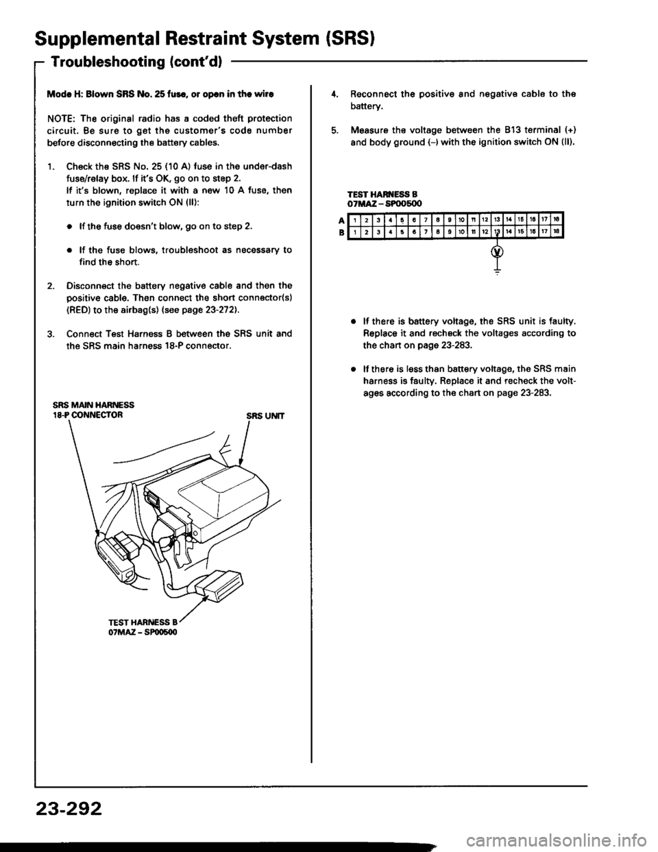
Modc H: Blown SRS No. 25 fur., ol opcn in the wire
NOTE: The original radio has a coded theft protection
circuit. Be sure to get the customer's code number
betore disconnecting the battery cables.
1. Ch€ck the SRS No. 25 (10 A) fuse in the under-dash
fuse/relay box. lf it's OK, go on to step 2.
lf it's blown, replace it with a now 10 A fuse, then
turn the ignition switch ON (ll):
. lf the fuse doesn't blow, 90 on to step 2.
. lf the fuse blows. troublsshoot as necessary to
find th6 short.
2. Disconnect the battery negative cable and then the
positive cable. Then connect the short connector(sl
(RED) to the airbag(s) (see page 23-272).
3. Conn€ct Teat Harnsss B between the SRS unit and
the SRS main harness 18-P connector.
SRS UNIT
23-292
23a7a10nl3161a17ra
26161oll12161a17|a
Reconnect th6 positiv€ 8nd negative cable to the
battery.
Measure ths voltage between the 813 terminal (+)
and body ground {-)with the ignition switch ON (ll).
TEST HAN ESS BoTMA:Z - SPOOs{X'
lf there is battery voltage, the SRS unit is faulty.
Replace it and rscheck the voltages according to
the chan on page 23-283.
lf there is lsss than b8ttery voltage, the SRS main
harness is faulty. Replace it and recheck the volt-
ag6s according to the chart on page 23-283.
Page 1405 of 1413

Supplemental Restraint System (SRSI
Airbag Assembly Disposal (cont'd)
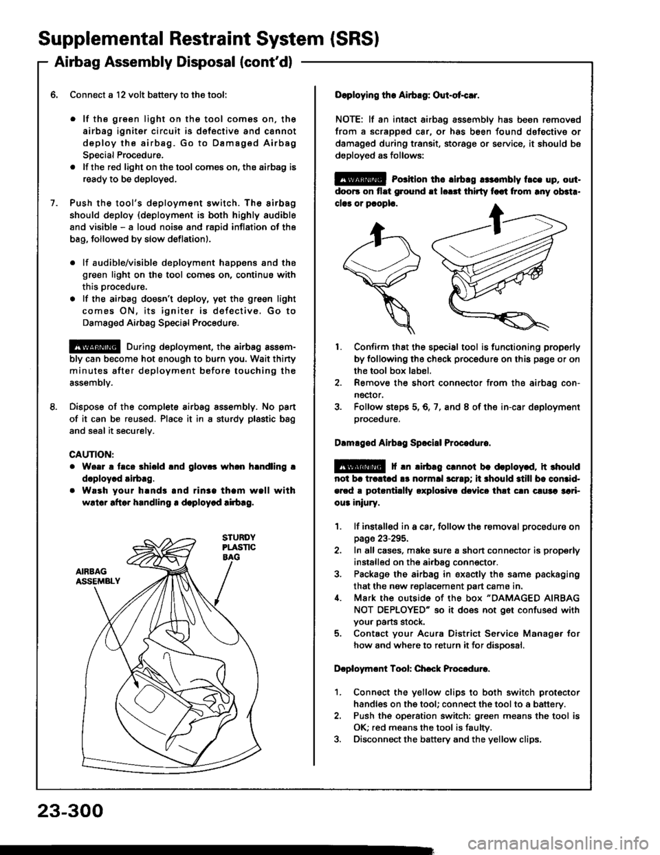
Connect a l2 volt batterv to the tool:
. lf the green light on the tool comes on, th€
airbag igniter circuit is d€fective and cannot
deploy the airbag. Go to Dsmag€d Airbag
Special Procedure.
. lf the red light on the tool comes on, the airbag is
ready to be deployed.
Push the tool's deployment switch. Th6 sirbag
should deploy (deployment is both highly audible
and visibls - a loud noise and raDid inflation of the
bag, followed by slow deflationl.
. lf audible/visible deploym€nt happsns and the
green light on the tool comes on, continus with
this Drocedure.
. lf the airbag doesn't deploy, yet the green light
comes ON, its igniter is dofectiv€. Go to
Damaged Airbag Special Procedure.
@ During deploym€nt, the airbsg assom-
bly can become hot enough to burn you. Wait thirty
minutes after deployment beforo touching the
assemblv.
Dispose of the complete airbag sssembly. No pan
of it can be reused. Place it in I sturdy plastic bag
and seal it securelv.
CAUTION:
Woar a taco shiold lnd glov.s whon hlndling !
doploy.d airbag.
Waeh your hands and rin3a tham wall with
wslor aftor handling r deploycd !irb!g.
23-300
Doploying the Airbag: Out-ot{!r.
NOTE: lf an intsct airbag assembly has been removed
from a scrapped car, or has been found dofective or
damagsd during transit, storage or service, it should bs
dsployed as follows:
@ Porition th6 lirbrg rr:.mbly t.ce up, out-
doo6 on flat ground !t lorrt thirty foot from rny ob3t..
clar or pcoplo.
1. Confirm that the special tool is functioning properly
by following the check procedure on this page or on
the tool box label.
2. Remove the short connector from the airbag con-
nector.
3. Folfow steps 5,6,7, and 8 of the in-car deployment
orocequre.
Dlmlged Airbsg Sp.ci8l Procoduro.
E!@ f rn lirbag crnnot be deploy.d, it rhould
not br trcltcd !s normll scrrp; ii 3hould still bc comid-
ercd a potantillly oxplolivr dcvicc thli cln c!u3a 3ari-
ou3 iniury.
1. lf instslled in a car, follow the removal procedure on
page 23-295.
2. In all cases, make sure a short connector is properly
installed on the airbag conn€ctor.
3. Package the airbag in sxacily the same packaging
that the now replacement part cama in.i[. Mark the outside 0f the box "DAMAGED AIRBAG
NOT OEPLOYED" so it does not get confused with
your parts stock.
5. Contact your Acura District Service Manager for
how and where to return it for disoosal.
Dcploymont Tool: Chcck Procedure.
1. Connect the yellow clips to both switch protector
handles on the tool; connect the tool to a battery.
2. Push th€ operation switch: green means the tool is
OK; red means the tool is faulty.
3. Disconnect the battery and the yellow clips.