Page 1171 of 1413
S€d8n:
,.-*-{.4rr-*Powgr door lock contrclunitDrivor's door lock actustorD ve/s door lock key cylind€l rwhchDdv6r's door lock switch
] Power window mrster switch)
Drivor's soat bolt swhch
Brx,4/vHr --E
lfr] ff;nj *",r *n
Irunk latch swhchf l8iler lighting connectorLicoruo pl.to lightsRioht I .L€-ft J nnst rrn gnr
Riohr ) .... .L€-ft J ran||gnr
Power anlonna mototHigh mo0nt bt'k6lightRear window dotoggor
] oo "onuo,unn
t,*----l ,_^
=,-"*- - f ABs contrclunh
@:
@:
E'
Ddvo/s door wir€ hemoss
ABS sub - hafn6s.
G5o2
otoa
.:
G702
23-65
Page 1255 of 1413

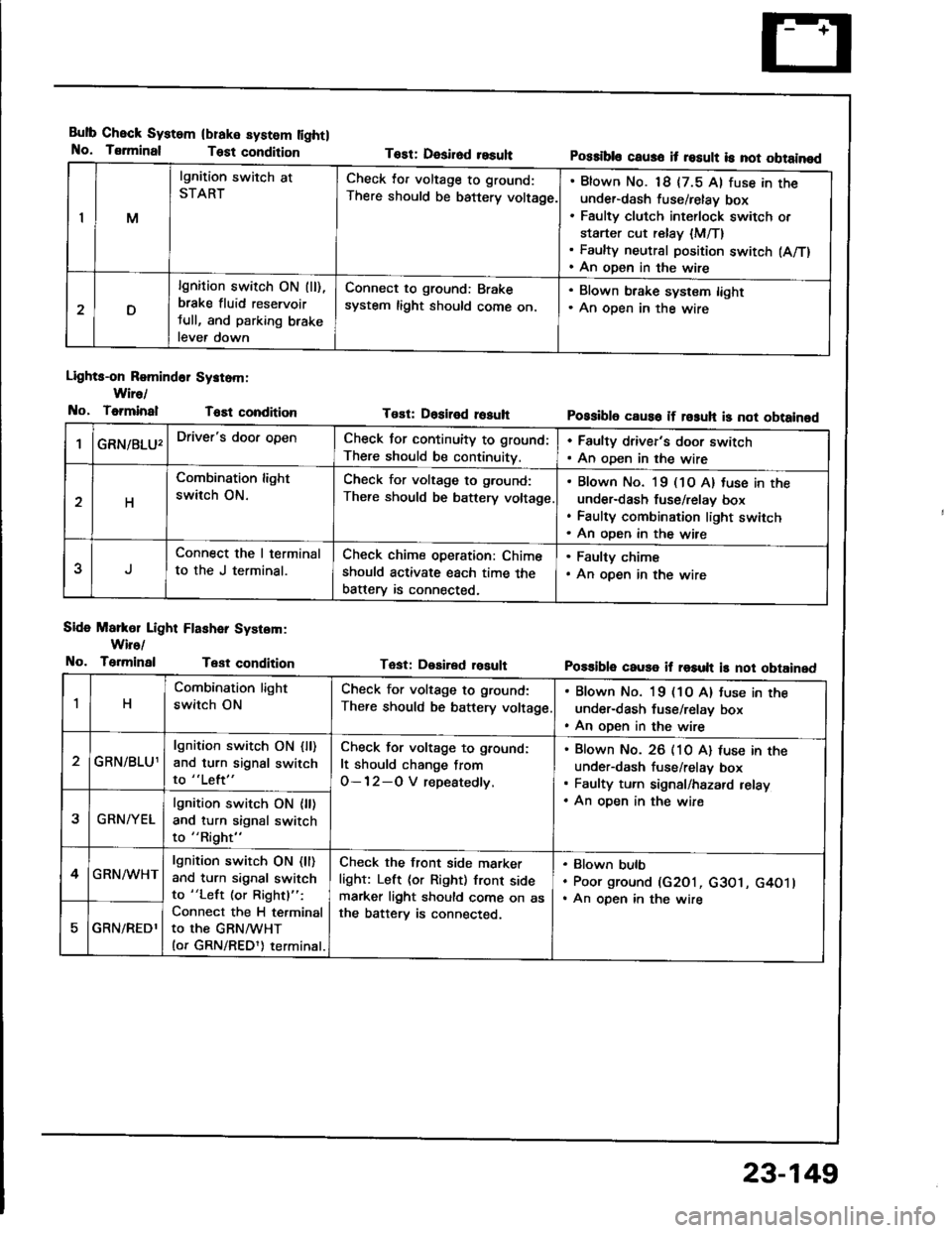
Bulb Check System
No. Tsrminal
(blake system lightl
Test condition
Lights-on Romind6r Systom:
Wire/
No, ToiminalT6Et condition
Side Markol Light Flashar System:
Wiro/
No. TerminalTest condition
Tost: Desirod resuhPossibls caus6 it result is not obtainod
Tost: Dositod rosuhPossibl6 caus6 if rosuh is not obtainod
Tast: Desired rosultPo$ible cause if result is not obtained
IM
lgnition switch at
STARTCheck lor voltage to ground:
There should be battery voltage.
Blown No. 18 {7.5 Al fuse in theunder-dash fuse/relay box
Faulty clutch int€rlock switch or
starter cut relay {M/T}Faulty neutral position switch (A/T)
An open in the wire
D
lgnition switch ON (ll),
brake fluid reservoir
tull, and parking brake
lever down
Connect to ground: Brake
system light should come on.
. Blown brake system light. An oDen in the wire
GRN/8LU'Driver's door openCheck for continuity to ground:
There should be continuity.
. Faulty driver's door switch. An oDen in the wire
H
Combination light
switch ON.
Check for voltage to g.ound:
There should be battery voltage
Blown No. l9 (1O A) tuse in the
under-dash fuse/relav box
Faulty combination light switch
An oDen in the wire
5
Connect the I terminal
to the J terminal.
Check chime operation: Chime
should activate each time the
batterv is connected,
. Faulty chime. An open in the wire
1H
Combination light
switch ON
Check for voltage to ground:
There should be battery voltage
. Blown No. 19 (1O A) tuse in the
under-dash fuse/relay box. An open in the wire
GRN/BLU1
lgnition switch ON {ll)and turn signal switch
to "Left"
Check for voltage to ground:
It should change from
O-12-O V repeatedly.
Blown No. 26 (10 A) luse in theunder-dash fuse/relav box
Faulty turn signal/hazard relay
An oDen in the wire2GRN/YEL
lgnition switch ON {ll)and turn signal switch
to "Right"
4GRN/WHTlgnition switch ON (ll)
and turn signal switch
to "Left (or Rightl":
Connect the H terminal
to the GRNMHT(or GRN/REDl) terminal.
Check the front side marker
light: Left (or Right) front sidemarker light should come on asthe batterv is connected.
Blown bulb
Poor ground (G2O1, c3O1, G4O1lAn open in the wire
GRN/REDl
23-149
Page 1339 of 1413
Power Door Locks
Component Location Index
1
FRONT PASSENGER'S DOOR LOCK ACTUATORTest. pago 23-239Reolacement. section 20
FRONT PASSENGER'SDOOR LOCK SWITCHfest, page 23-241
FRONT PASSENGER'S DOOR KEYCYLII{DER SWITCHTest, page 23-240
POWER OOOR LOCKCONTROL UNITfnput Tost, page 23-236
RIGHT REAR DOOR LOCK ACTUATOR lsodanlTest,
DOORKEY CYLINDER SWITCHTest. page 23-24O
DBIVER'S
DOOR
LOCK ACTUATORTest, page 23-238Roplacement, seclion 20
LOCK SWITCH'lest, page 23-241
Description
For this model, a new door lock system has been adopted to improve convenience and safety. lf the kev is insened intothe driver's door key cylinder, turned to the unlock position, and pulled out immediately thereafter, oNLy the driver.sdoor will unlock. However, if the key is kept in the unlock position tor one second or more, ALL doors wi
unlock.
23-239
LEFT REAR DOOR LOCK ACTUATOR {Sodan}Test, page 23-239
23-233
Page 1340 of 1413
Power Door Locks
Circuit Diagram
BATTENY
@'"t
BLK
.&;
G201G401
o00R toc( KN08
VL____I
FROMTPASSENGER'SoooR t-ocKACIUATOR
@r
I uFt REAR000R LocKACTUATOR
@"
r RIGHT REAR000R LocKACTUATOR
@'
8LK
A=
G501G5o2
I
G501G5o2
UiIDER- HOOD FUSE/RELAY BOX
No.41 l100Al iJo,36l50A)
DRIVER'S OOOBKEY CYI,INDERswITcH
DRIVER'SoooR rocKswtTcH
FRONTPASSENGEN'SDOOR LOCKswncH
POWER OOORLOCK CONTROI.
8rl(
A-l
GSotG502
23-234
I
Page 1341 of 1413

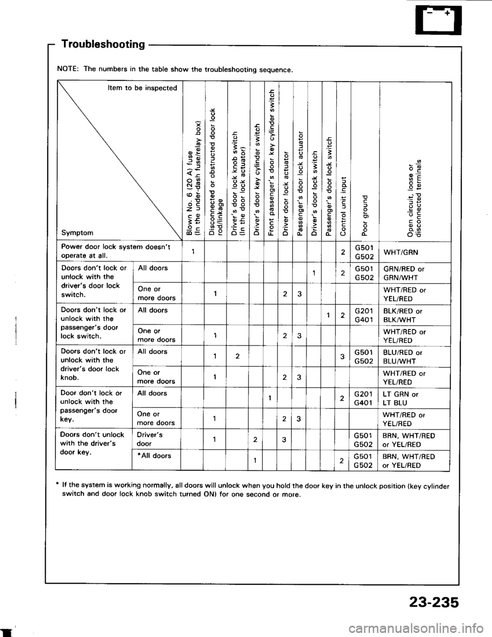
NOTE: The numbers in the table show the troubleshooting sequence.
Item io be inspected
Symptom
-9-.9)x<
St
z)
It9cdl=o'o
=3-
oo
oo
OE
;-s
.=3
o
;
c
TL
o
o
o
:
c
3
o
t
(L
c
o)
o-
9E-c
Power door lock system doesn't
ooerate at all.1G501
G502WHT/GRN
Doors don't lock or
unlock with the
driver's door lock
switch.
All doorsG501GRN/RED or
GRN^/lr'HT
One or
more doors1JWHT/RED or
YEL/RED
Doors don't lock or
unlock with the
passenger's doot
lock switch.
All doorsG201
G401
BLK/RED or
BLK/WHT
One or
more ooors1WHT/RED or
YEL/RED
Doo.s don't lock or
unlock with the
driver's door lock
knob.
All doors1G501
G502
BLU/RED or
BLU/WHT
One or
more ooors1WHT/RED or
YEL/RED
Doo. don't lock o.
unlock with the
passenger's doot
key.
All doorsG201
G401
LT GRN or
LT BLU
One or
more doors25WHT/RED or
YEL/RED
Doors don't unlock
wilh the driver's
door key.
Oriver's
ooorG501
G502
BRN, WHT/RED
or YEL/RED
'All doorsIGsol
G502
BRN, WHT/RED
or YEL/RED
Troubleshooting
+ It the system is working normally, €lldoors will unlock when you hold the door key in the unlock position (kev cvlinderswitch and door lock knob switch turned ON) for one second or more.
23-235
Page 1342 of 1413
Power Door Locks
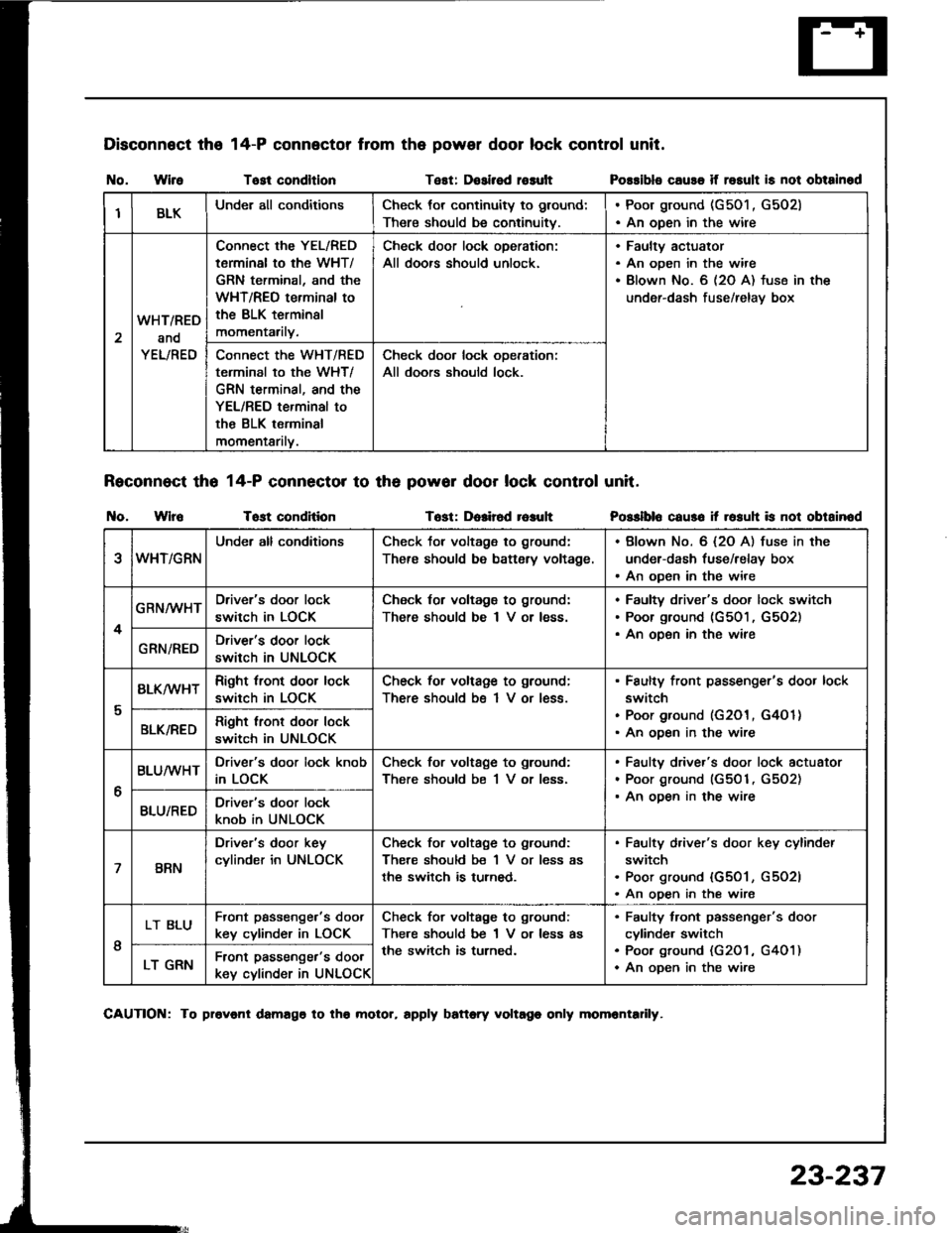
Control Unit Input Test
Remove the driver's door panel {see section 2O).
Disconnect the 1+P connector Jrom the control unit.
Inspect the connector and socket terminals to be
sure they are all making good contact.
a It the terminals are bent. loose or corroded, repair
them as necessary. and recheck the system.
a lf the terminals look OK. make the following in-
put tests at the connector.- lf any test indicates a problem, find and cor-
rect the cause, then recheck the syslem.
lf all the input tests prove OK, the control unit
must be faultv; replace it.
POWER DOOR LOCK
CONTROL UNIT
t4-P COI{NECTOR
View from wiro side
23-236
Page 1343 of 1413

Disconnect the
I{o. WireTost condltlonTest: Dosirsd rosult
Reconnect tho 14-P connector to th6 powor door lock control unit.
t{o. WlroTost conditionTost: Dolir6d r6auh
14-P connector from the power door lock control unit.
Possibls cause if rosult is not obtainod
Posslblo caus6 it rosuh is not obtainod
IBLKUnder all conditionsCheck tor continuity to ground:
There should be continuitv.
. Poor ground (G501 , G502). An open in the wire
2
WHT/RED
and
YEL/RED
Connect the YEL/RED
tarminal to the WHT/
GRN terminal, and the
WHT/REO terminal to
the BLK terminsl
momentarily.
Check door lock oDeration:
All doors should unlock.
Faultv actuator
An open in the wire
Blown No. 6 (2O A) fuse in the
under-dash fuse/relav box
Connect the WHT/RED
terminal to the WHT/
GRN terminal, and the
YEL/RED terminal to
the BLK terminal
momentarilv.
Check door lock ooeration:
All doors should lock.
eWHT/GRN
Under all conditionsCheck tor voltage to ground:
There should be battsry voltage.
. Blown No. 6 {2O A) fuse in the
under-dash fuse/relay box. An open in the wire
4
GRN/WHTDriver's door lock
switch in LOCK
Check for voltagg to ground:
There should be I V or less.
Faultv driver's door lock switch
Poor ground (G501, G5O2)
An oDen in the wireGRN/REDDriver's door lock
switch in UNLOCK
I
BLK/wHTRight tront door lock
switch in LOCK
Check for voltage to ground;
There should bs 1 V or less.
Faulty front passenger's door lock
switch
Poor ground (G201, G4O 1)
An ooen in the wireBLK/REDRight lront door lock
switch in UNLOCK
6
BLUMHTDriver's door lock knob
in LOCK
Check for voltage to ground:
There should be 1 V or less.
Faulty driver's door lock actuator
Poor ground (G501, G5O2)
An ooen in the wireBLU/REDDriver's door lock
knob in UNLOCK
7BRN
Driver's door key
cylinder in UNLOCK
Check for voltage to ground:
There should be 1 V or less as
the switch is turned.
Faulty d,iver's door key cylinder
switch
Poor ground {G501, G5O2l
An open in the wire
I
LT BLUFront passenge.'s doot
key cylinder in LOCK
Check for voltage to ground:
There should be 1 V or less as
the switch is turned.
Faulty tront passenger's door
cylinde. switch
Poo. ground (G201 , G401)
An oDen in the wireLT GRNFront passenger's door
key cylinder in UNLOCK
CAUTION: To provonl damago to tho molor, rpply battory voltago only momrntadly.
23-237
Page 1344 of 1413
1.
Power Door Locks
Driver's Door Lock Actuator Test
Remove the door panel (see section 20).
Disconnect the 6-P connector from the actuator.
Check actuator operation by connecting power and
ground according to lhe table.
CAUTION: To prevont damago lo tho actualol, ap-
ply battery voltage only momentarily.
lf the actualor fails to work properly, replace it.
Terminal
;;"
---\D
LOCK@o
UNLOCKlJ@
23-238
Terminal
il;----tI
LOCKoo
UNLOCKo--o
5. Check fo. continuity between the terminals in each
switch position according to the table.
DOOR LOCK KI{OB