Page 157 of 1413

I
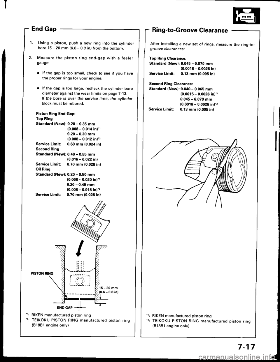
'1. Using a piston, push a new ring into the cylinderbore 15 - 20 mm (0.6 0.8 in) from the boftom.
Measure the piston ring end-gap with a feelergauge:
lf the gap is too small. check to see if you have
the proper rings for your engine.
lf the gap is too large, recheck the cylinder bore
diameter against the wear limits on page 7-13.
ll the bore is over the service limit, the cylinder
block must be rebored.
Piston Ring End-cap:
Top Ring
Standard (New): 0.20 - 0.35 mm(0.008 - 0.01'l inl'1
0.20 - 0.30 mm
10.008 - 0.012 inl''
Servica Limit: 0.60 mm (0.024 in)
Second Ring
Standard (Now): 0.40 - 0.55 mm
10.016 - 0.022 in)
Service Limit: 0.70 mm (0.028 in)
Oil Ring
Standard (New): 0.20 - 0.50 mm(0.008 - 0.020 in)'1
0.20 - 0.,15 mm
{0.008 - 0.018 inl',
Servica Limit: 0.70 mm 10.028 in)
After installing a new set of rings, measure the ring-to-gfoove clearances:
Top Ring Cl€arance:
Standard lNewl: 0.045 - 0.070 mm
10.0018 - 0.0028 in)
Service Limit: 0.13 mm {0.005 inl
Second Ring Clearance:
Standard {Newl: 0.040 - 0.065 mm(0.0015 - 0.0026 inl'1
0.0i15 - 0.070 mm(0.0018 - 0.0028 in)',
Service Limit: 0.13 mm (0.005 inl
iliiii.--r.llli.j- --.-PISTON NING
ioi
---'z llEND GAP -11--
RIKEN manufactured piston ring
TEIKOKU PISTON RING manufactured oiston rinq
{81881 engine only)
RIKEN manufactured piston ring
TEIKOKU PISTON RING manufactured Diston rino(B'1881 engine only)
7-17
Page 162 of 1413

Connecting Rods
Selection
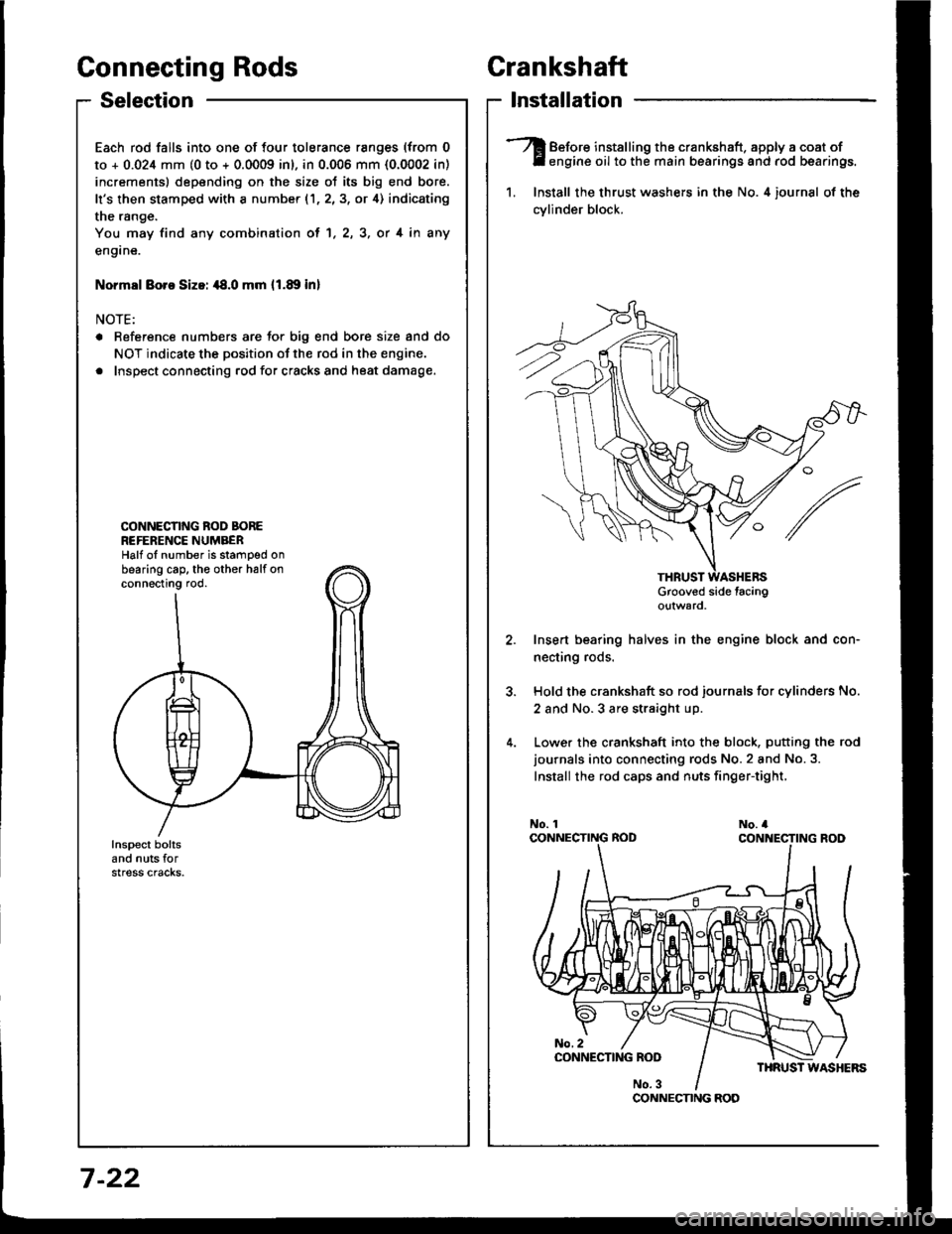
Each rod falls into one of four tolerance ranges (from 0
to + 0.024 mm (0 to + 0.0009 inl, in 0.006 mm {0.0002 in)
increments) depending on the size ot its big end bore.
It's then stamped with a number (1,2,3, or 4) indicating
the range.
You may find any combination ol 1, 2, 3, or 4 in any
engane.
Normsl Boro Sizoi ,18.0 mm 11.89 inl
NOTE:
a Reference numbers are Jor big end bore size and do
NOT indicate the position of the rod in the engine.
. Inspect connecting rod for cracks and heat damage.
CONNECNNG ROD BOREREFERENCE NUMBERHalf oI number is stamped onbearing cap. th€ other halfonconnecting rod.
Crankshaft
lnstallation
Before installing the crankshaft. apply a coat ofengine oil to the main bearings and rod bearings.
1. Install the thrust washers in the No. 4 iournsl of the
cvlinder block.
Grooved side tacingo!tward
Insert bearing halves in the engine block and con-
necting rods.
Hold the crankshaft so rod journals for cylinders No.
2 and No.3 are straight up.
Lower the crankshaft into the block. putting the rod
journals into connecting rods No.2 and No.3.
Install the rod caps and nuts finger-tight,
CONNECNNG ROD
7 -22
Page 164 of 1413

Grankshaft
Installation (cont'd)
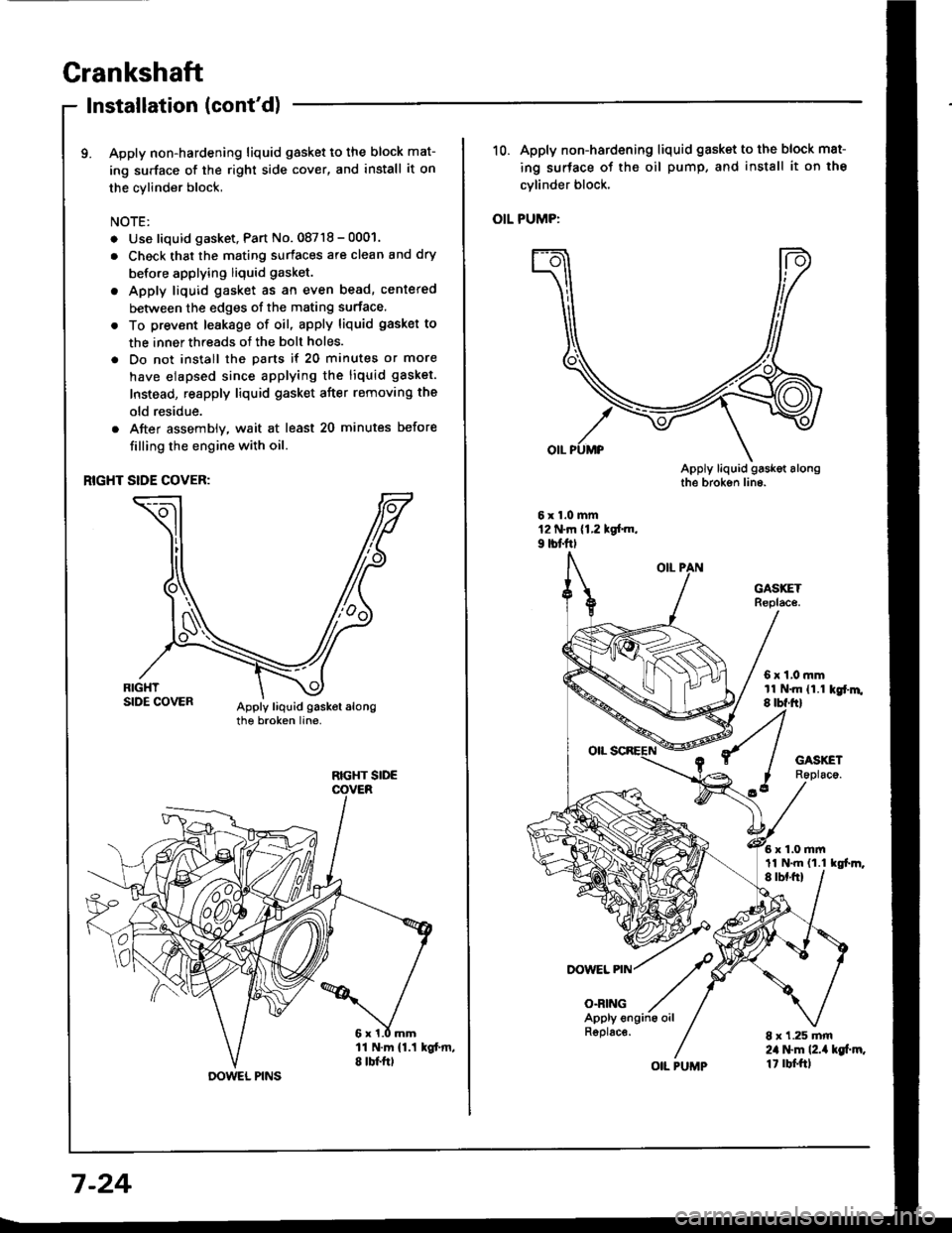
9. Apply non-hardening liquid gasket to the block mat-
ing surface of the right side cover, and install it on
the cylinder block,
NOTE:
. Use liquid gasket, Part No. 08718 - 0001.
. Check that the mating surfaces are clean and dry
before applying liquid gasket.
. Apply liquid gasket as an even bead, centered
between the edges of the mating surface.
. To prevent leakage of oil, apply liquid gasket to
the inner threads of the bolt holes.
. Do not install the parts if 20 minutes or more
have elapsed since applying the liquid gasket.
Instead, reapply liquid gasket after removing the
old residue.
. After assembly, wait at least 20 minutes before
filling the engine with oil.
RIGHT SIDE COVER:
RIGHT SIDE
DOWEL PINS
7-24
R6plac€.
OIL PUMP
10. Apply non-hardening liquid gasket to the block mat-
ing surface of the oil pump, and install it on the
cvlinder block.
OIL PUMP:
DOWEL PIN
O.RING
6x1,0mmtl N.m {1.1 kgr'm.8 tbf.ftl
6x1.0mm
8 x 1.25 mm2il l$m l2.ia kg[.m.1t rbf.ftl
11 N.m {1.1 tgl.m,
Page 165 of 1413
11.lnstallthe oil screen.
Installthe oil pan.
NOTE: Clean the oil pan gasket mating surfaces.
Tighten the bolts as shown below.
Torque: 12 N.m {1.2 kgf.m, 9 lbf'ft)
NOTE: Tighten the bolts and nuts in two steps and
toroue the bolts in a crisscross pattern
1'�I
Oil Seal
lnstallation
The seal surface on the block should be dry.
Apply a light cost of oil to the crankshaft and to
the liD of the seal.
Drive in flywheel end seal against right side cover.
NOTE: Drive the end seal in squarely.
DRIVER07t,49 - (xll(xtoo
2. Confirm that clearance is equal all the way around
with a fe€ler gauge.
Cler.6nce: 0.5 - 0.8 mm (0.02 - 0.03 inl
RIGHT SIDECOVER
NOTE: Reter to right column and 8-10 lor installa-
tion of the oil pump side oil seal.
lnstall sealwith thepart number sidetacing out.
7-25
Page 166 of 1413
Installation (engine removal not
S€AL DRIVEB07LAD - PRimroAlnstallse6lwith tho
Pan numbertacing out.
Using the special tool, drive in the flywheel-end seal
until the driver bottoms against block.
NOTE: Align the hole in the drivsr attachment withthe Din on the crankshaft.
Oil Seal
required)
The seal surface on the block should b€ dry.Apply a light coat of grease to the crankshaft andto the lio of seal.
Using the special tool, drive in the timing pullsy-
end seal until the driver bottoms against the oilpump.
When the seal is in place, clean any excess grease
off lhe crankshaft and check that the oil seal tiD isnot distoned.
7-26
Page 169 of 1413

lllustrated Index
DRATT PIUG \44 .m (4.5 tgf.m, 33 lbf'ftl \Do not ovgr tightgn. \-@5
OIL PAI{
6 r l.O mtn121{.m 11.2 kol.m,I lbl.ttl
CAUTIOIiI: Do not ovortighten the drain plug.
81881 sngine:
WASHERReplace.
O|L BNEATHERTAIIK
eq
nU2o@
\
u
I
#-'
GASKETR6placs,
NOTE;
o Use new O-rings when reassembling.
a Apply oil to O-rings betore installation,
. Use liquid gasket, Part No. O8718-OOO1.
a Clean the oil pan gasket mating surtaces before in-
stalling it.
6 x'l.o mm12 N.m {1.2 kgt.m, 9 lbt.tt)
6 x 1.0 mm'11 N.m 11 .1 kgt'm,8lbt.ftl
6 x 1.O mmll N.m {1.1 kgf'm,
OIL SCREEN
A
,F
HEAD OILCONTROL ORIFICECIean.
I tbt.ftl
OIL FILRepl.cemont, p6gs 8-6
ENGINE OIL PRESSUREswlTcH18 .m 11.8 kgl.m, 13lbl.ftl'l/8 in. BSP lgritish StandardPioo Taporl 28 Threads/inch.Use propgr laquid 56alant.
GASKETReplace.
BAFFLE PTATE
I x 1.25 mm24 N.m 12.4 kgf..n,17 rbr.ftl
6 x 1.O mm11 N-m (1.1 kgt.m,8lbf.ft)OIL PUMPOverhaul, page 8-9lnspection page, 8-1OApply liquid gasket toblock mating surlace.(cont'dl
8-3
Page 170 of 1413

lllustrated Index
(cont'dl
CAUTION: Do not overtighten rhe dlain ptug.
818C1 engine:
NOTE:
a Use new O-rings when reassembling.
a Apply oil to O rings before installation.. Use liquid gasket. Part No. 08718-OOO1.
a Clean the oil pan gasket mating surfaces before in-
stalling it.
OIL PAN
Replace.
6 x 1.0 mm12 N.m 11.2 kgl.m, 9 lbf.ftl
6 x 1.0 mm11 N.m 11.1 kgt.m,S lbf.fil
OIL JET BOLT16 N.m {'1.6 kgf.m, '13 lbf.ft}
OIL JETBe careful not to damage.Inspection, page 8-8
O-RINGReplace.
EAFFLE PLATE
6xl.0mm11 N.m (1.1 kgt.m, I lbt.ft)
OIL SCREEN
GASKETReplace.
6 r '1.0 mml1 N.m (1.18 rb-trlK9-m,
O-RINGReplace.
HEAD OIL CONTROLORIFICEClean.
8 x 1.25 mm24 N.m (2.4 kg-m, 17 lb-ft)ENGINE OIL PR€SSUREswtTcH1A N.m {1.8 kgf.m, 13 lbf.ft)1/8 in. BSP {British StandardPipe Taperl 28 threads/inch.Use proper liquid gasket.
OIL PUMPOverhaul, page 8-9Removal/lnspection/lnstallation, page 8-10Apply liquid gasket to matingsurface ot the engine block.
Il
,--)e6V
ENGINE OIL COOLER
ENGINE OIL FILTERReplacement, page 8-6
OIL COOLERCE TER BOLT74 N.m (7,5 kgf.m, 54 lbf.ft)
DRAIN PLUG44 N.m (4.5 kgf.m, 33 lbt.ftlDo not overtighten.
8-4
Page 172 of 1413

Englne Oil
Replacement {cont'd)
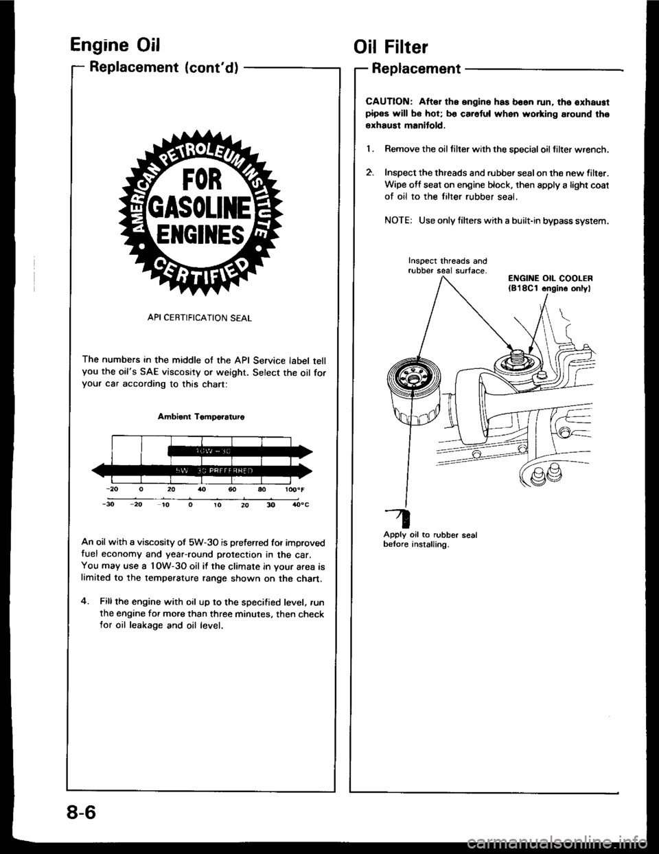
API CERTIFICATION SEAL
The numbers in the middle of the API Service label tellyou the oil's SAE viscosity or weight. Select the oil foryour car according to this chart:
Ambient TomDo?aturo
An oil with a viscosity of 5W-3O is preferred for improvedfuel economy and year-round protection in the car.You may use a l OW-3O oil it the climate in your area islimited to the tempe.ature range shown on the chart.
4. Fillthe engine with oil up to the specified level, .un
the engine for more than three minutes. then checklor oil leakage and oil level.
ElrclltEs
Oil Filter
Replacement
CAUTION: Aftar the ongine has boan run. tho oxhaustpipos will bo hot; b€ caretul when wo.king around tho
erhaust manitold,
Remove the oil tilter with the special oil filter wrench.
Inspect the threads and rubbe. sealon the new lilter.
Wipe off seat on engine block. then apply a light coat
of oil to the tilter rubber seal,
NOTE: Use only filrers with a built-in bypass system.
Inspect threads andrubber seal surface-
Apply oil to rubber sealbetore anstalling.
ENGINE OIL COOLER(8'l8Cl ongino onlyl
8-6