1994 HONDA INTEGRA Bearings
[x] Cancel search: BearingsPage 156 of 1413

Piston
lnstallation
'1.
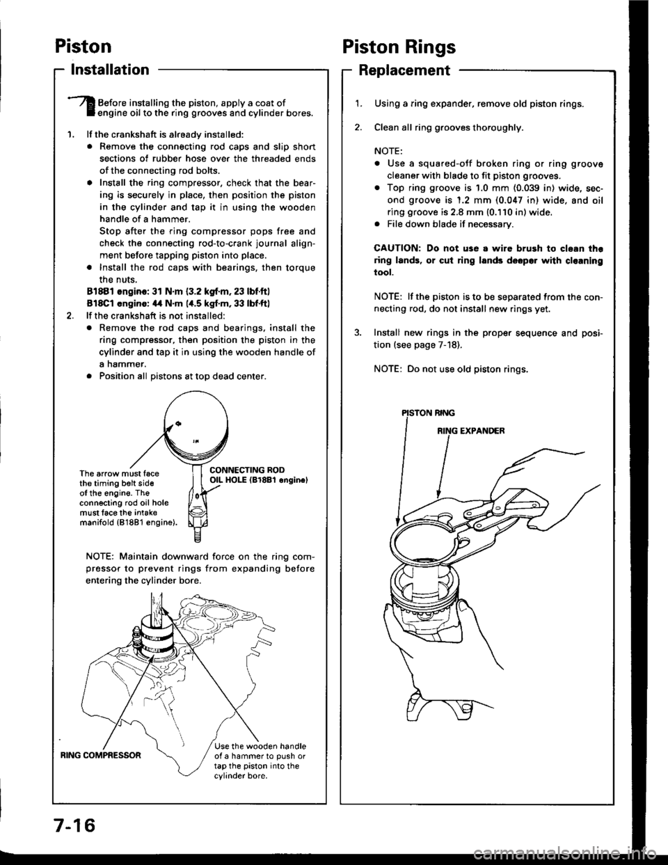
Before installing the piston, apply a coat ofengine oil to the ring grooves and cylinder bores.
lf the crankshaft is already installed:
. Remove the connecting rod caps and slip short
sections of rubber hose ove. the threaded ends
of the connecting rod bolts.
a Install the ring compressor, check that the bear'
ing is securely in place, then position the piston
in the cylinder and tap it in using the wooden
handle of a hammer.
Stop after the ring compressor pops free and
check the connecting rod-to-crank journal align-
ment before tapping piston into place.
. Install the rod caps with bearings, then torque
the nuts,
81881 ongino: 31 N.m {3.2 kgf.m, 23 lbf.ftl
818C1 cngino: 44 N'm 1,t.5 kgf.m, 33 lbf.ftl
lf the crankshaft is not installed:
o Remove the rod caps and bearings. install the
ring compressor, then position the piston in the
cylinder and tap it in using the wooden handle of
a nammer.
. Position all Distons at toD dead center.
CONNECTING RODOIL HOI-E (Br8Bl onginelThe arrow must facethe timing belt sideof the engine. Theconnecting rod oil holemust lace the intak€manifold {81881 €ngine).
NOTE: Maintain downward force on the ring com-
pressor to prevent rings from expanding before
entering the cylinder bore,
BING COMPRESSORUse the wooden handleof a hammer to push ortap the piston into thecylinder bore.
Piston Rings
Replacement
1.Using a ring expander, remove old piston rings.
Clean all ring g.ooves thoroughly.
NOTE:
. Use a squared-oJf broken ring or ring groove
cleaner with blade to fit piston grooves.
. Top ring groove is 1.0 mm (0.039 in) wide, sec-
ond groove is 1.2 mm (0.047 in) wide. and oil
ring groove is 2.8 mm (0.110 in) wide.. File down blade if necessary.
CAUTION: Do not use a wire brush to cloan thr
ring lands, or cut ring lands dsopo. with cl€aning
tool.
NOTE: lf the piston is to be separated from the con-
necting rod, do not install new rings yet.
Install new rings in the prope. sequence and posi-
tion (see page 7-18).
NOTE: Do not use old piston rings.
Page 162 of 1413

Connecting Rods
Selection
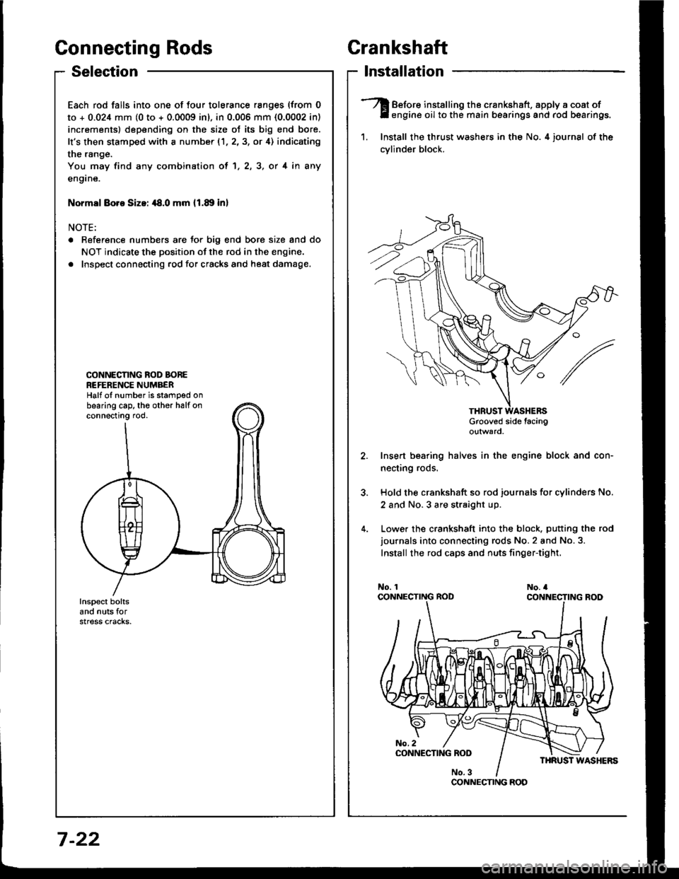
Each rod falls into one of four tolerance ranges (from 0
to + 0.024 mm (0 to + 0.0009 inl, in 0.006 mm {0.0002 in)
increments) depending on the size ot its big end bore.
It's then stamped with a number (1,2,3, or 4) indicating
the range.
You may find any combination ol 1, 2, 3, or 4 in any
engane.
Normsl Boro Sizoi ,18.0 mm 11.89 inl
NOTE:
a Reference numbers are Jor big end bore size and do
NOT indicate the position of the rod in the engine.
. Inspect connecting rod for cracks and heat damage.
CONNECNNG ROD BOREREFERENCE NUMBERHalf oI number is stamped onbearing cap. th€ other halfonconnecting rod.
Crankshaft
lnstallation
Before installing the crankshaft. apply a coat ofengine oil to the main bearings and rod bearings.
1. Install the thrust washers in the No. 4 iournsl of the
cvlinder block.
Grooved side tacingo!tward
Insert bearing halves in the engine block and con-
necting rods.
Hold the crankshaft so rod journals for cylinders No.
2 and No.3 are straight up.
Lower the crankshaft into the block. putting the rod
journals into connecting rods No.2 and No.3.
Install the rod caps and nuts finger-tight,
CONNECNNG ROD
7 -22
Page 163 of 1413

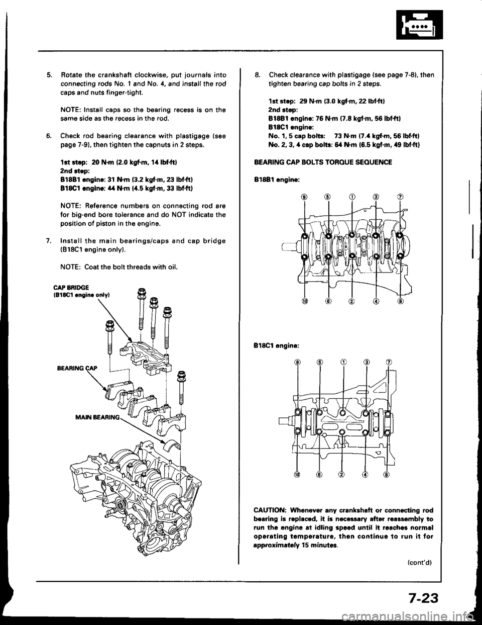
Rotate the crankshaft clockwise, put journals into
connecting rods No. 1 and No. 4, and install the rod
caps and nuts finge.-tight.
NOTE: lnstall caps so the bearing recess is on the
samg side as the .ecess in the rod.
Check rod bearing clsarance with plastigage (see
page 7-9), then tighten the capnuts in 2 steps.
l3t 3t.p: 20 N.m (2.0 kgf.m, rl btfil
2nd 3tep:
81881 cnginc: 31 N.m (3.2 kgf.m, 23 lbf.ft)
818C1 .ngin!: ,14 N.m (4.5 kgt.m,33 lbf.ft)
NOTE: Reference numbers on connecting rod are
for big-end bore tolorance and do NOT indicate the
positioo of piston in the engine.
Install the main bearings/caps and cap b.idge(818C1 engine onlyl.
NOTE: Coat the bolt threads with oil.
CAP BRIDGElBlSCl .noin. onlyl
EEARIlTG
8. Check clearsnce with plastigsge (see page 7-8). then
tighten bearing cap bolts in 2 steps.
13t st.p: 29 N.m (3.0 kgf.m, 22 lbt.ftl
2nd 3tsp:
81881 .ngin.: 76 N.m (7.8 kgt.m,56 lbf,ft)
Bl8Ct engine:
No. 1, 5 cap bol$: 73 N.m (7./r kgf'm, 56 lbf,ftl
No. 2, 3, a clp bolbr 6{ N.m (6.5 kgf'm, /r9 lbf,ftl
BEARING CAP BOLTS TOROUE SEOUENCE
Bl88l cngino:
Bl8Cl ongino:
CAUTION: Whenever any crsnkehaft or connocting rod
b.aring is rlphccd. it i5 ncccrsrry aftor rclssombly to
run tho ongino ai idling 3p6ad until it re.chei normrl
opcrating tcmporature, thon continuo to run it fol
spp.oximltoly f 5 minula3.
(cont'd)
7-23
Page 350 of 1413

lllustrated Index
Refer to the drawing below for the transmission disassembly/reassembly.
Clean all the parts thoroughly in solvent and dry with compressed air.
I ruurlcate att the parts with oil before reassembly.
NOTE:
. This transmission uses no gaskets between the major housings; use liquid gasket (P/N 08718-0001)
{see page 13-43).
a
a
Alwavs clean the magnet @ whenever the transmission housing is disassembled.
Inspect all the bearings for wear and operation.
(9
@
@
tqqlnl^'1ult I Ej
nl
11-4fi
,\|j Uh
o
@
o
@@
@
@
(3
(,
@
@
@
a
@
@
@
@
B
tg
Y
o
@
@
@
*N
13-8
[@.--oaF5i,--@:7
Page 351 of 1413

12 N.m (1.2 kgim,9 lbnft)
15 N.m (1.5 kgnm, 11 lbf.ft)
15 N.m (1.5 kgf.m, 11 lbf.ft)
24 N.m (2.4 kgf.m, 17 lbf'ft)
27 N.m (2.8 kgnm,20 lbnft)
30 N.m (3.1 kgf.m, 22 lbf'ft)
Bolt Size
,l
{
@@69
@
@@@@@@@@6Dq0
o€xv0@
@0!@@@@al
61@
B
c
D
E
F
6x1.0mm
6x1.0mm
I x 1.0 mm
8 x 1.25 mm
8 x 1.25 mm
8 x 1.0 mm
i) BALL BEARINGe sroPPER R|NG9 TAPER RINGA NEEDLE EEARINGO SPACER.d SYNCHRO RINGt sYNcHRo SPR|NG!) 5TH/REVEFSE sYNcHRo SLEEVEO 5TH/REVERSE SYNCHRO HUB[0 sYrucxao nlrucii i) 5TH GEARO 38 x 43 x 26 mm NEEDLE BEARINGt3 SPACEE COLLARO 4TH GEAR.iB SYNCHRO FING.Ii9 SYNCHRO SPRING{, 3RD/,ITH SYNCHRO HUB
@ 3RD/4TH SYNCHBO SLEEVEt9 3RD GEARO MAINSHAFTO wasHER@) SPRING WASHER40 BALL BEARINGO 28 x 41 x ? mm OIL SEAL Replace.ad 35 x 56 x 8 mm OIL SEAL Replace.a0 14 x 20 mm OOWEL PIN@ OIL CHAMBER PLATE'A BEVERSE IDLEN GEAR SHAFT@ wasHER t-2).A REVERSE IDLER GEAFO REVERSE CHANGE HOLDER3A sTH/REVERSE SHIFT PIECEO 1ST/2ND SHIFT FORK04 3RD/.TH sHlFr FoRK@ 5TH/REVERSE SHIFT FORKO9' OIL GUTTER PLATE6' SNAP RING@ 72 mm THRUST SHIM) OIL GUIOE PLATEi!0 10 mm WASHER Replace..4i] REVERSE IDLER GEAR SHAFT BOLT54 N.m {5.5 kgt m, 40lblftl) TRANSMISSION HANGER B(3 BREATHER CAP@ TRANSMISSION HANGER A63 BACK.UP LIGHT SWITCH25 N.m (2.5 ksf.m, 18lbfftl@r 14 mrn waSHER Replace.67 16 mm SEALING BOLT29 N.m (3.0 kgl.m, 22 lbf ft)@ 32 mm SEALING BOLT25 N.m (2.5 kgf.m. 18lbt'ft|@ 40 x 62 x 9 mm OIL SEAL Replace.D STEEL BALL D. 5/16 inGl SPRING L. 30 mm {1.2 in}
@ 12 mm WASHER Replace.63) SET SCREW22 N.m 12.2 kgl.m, 16 lbt'ft,@ OIL ORAIN PLUG39 N.m {4.0 kgt.m, 29 lbf'ftl€9 WASHER Replace.@ oIL FILLER PLUG4,1N.m 14.5 kgJ m, 33 lblftl
*1:81881 engine*2:B18Cl engine
WASHER Beplace.TRANSMISSION HOUSING80 mm SHIM (*1)79.5 mm SHIM {*21THRUST SHIM {*2IT. 2.0 mm (0.079 in)BEARING OUTER RACE {*2}SHIFT PIECE SHAFTINTERLOCKSHIFT PIECESHIFT ARM HOLDERSELECT ARMSELECT RETURN SPRING10 mm SHIM10 mm WASHERLOCK COLLAR3 x 16 mm SPRING PIN Replace.8 mm SPRING WASHERCHANGE PIECESET SCREW22 N.m {2.2 kgf.m, 16 lbf.ft}SPRING L.25.6 mm {1.01 inlSTEEL BALL D. 5/16 inMAGNETCLUTCH HOUSING14 x 25 x 16 mm OIL SEAL Replace.SHIFT RODDIFFERENTIAL ASSEMBLYSee section 15BEARING OUTER RACE I*2ITHRUST SHIM I*2)T. 2.5 mm (0.098 in,SHIFT ROD BOOTOIL GUID€ PLATE33 x 60 x 20 mm NEEDLE BEARINGBEARING RETAINER PLATELOCK WASHER Replace.COUNTERSHAFTTHRUST SHIM37 x 42 x 25 mm NEEDLE BEARINGlST GEARFRICTION DAMPERSYNCHRO RINGSYNCHRO SPRINGlST/2ND SYNCHRO HUBREVERSE GEARDOUBLE CONE SYNCHRO I*2ISYNCHRO BING I*1)FRICTION DAMPERSPACER42 x 6? x 24 mm NEEDLE BEARING2ND GEAR3RD GEAR4TH GEAS5TH GEARNEEDLE BEARINGBALL BEARINGSPRING WASHERLOCKNUT Replace.108 - 0- 108 N.m(11.0 - 0* 11.0 kgt m,80- 0- 80lbf.ft)5 x 22 mm SPRING PIN Replace.00
13-9
Page 393 of 1413

Automatic Transmission
'l4-2
14-3't 4-6
14-8
14-14
14-23
Hvdraulic Flow ...--...... 14-24
Lock-up System ........ 14-38
Eloctrical Systom
Component Location ............,...,................ I 4-45
Circuit Diagram ............. 14-46'Troubleshooting Procedures ........,..........., l4-48
Symptom-to-Component Chart
Electrical System ...... 14-50
Electrical Troubleshooting
Troubleshooting Flowchart .................... 14-52
Lock-uo Control Solenoid Valve A/8
Test .................. --.... \4-82
ReDlacement ,...,...,..,. 14-82
Shift Control Solenoid Vslve A/B
Test .................. ...... 14-83
Reolacement .............. 14-83
Transmission Control Module (TCM)*ReDlacement ........... 14-84
Mainshalt/CountershaJt SDeed Sensors
Reolacement ............. 14-85
Hydraulic Systom
Symptom-to-Component Chart
Hydraulic System
Road Test
Slall Speed
Test ..................
Fluid Level
Checking/Changing
Pressu.e Testing
Transmission
Transmission
Removal ............. ...... 14-99
lllustrated Index
Right Side Cover .................................. 1 4- 1 04
Transmission Housin9 ..................,,....... I 4-1 06
Torque Converter HousingNalve
Body .................. ... 14- 1O8
Right Side Cover
Removal ............. ...... 14-110
Transmission Housing
Removal ............. .-..-. 14-112
Torque Convener HousingNalve Body
Removal ............. ...... 14-114
Valve Caps
Description ................ 14-116
Valve Body
Repair ................ ...-.. 14-117
Valve
Assembly ...........
Oil Pump
Main Valve Body
Disassembly/lnspection/Reassembly
Regulator Valve Body
Disassembly/lnspection/Reassembly
Lock-up Valve Body
Disassembly/lnspection/Reassembly .......
Secondary Valve Body
Disassembly/lnspection/Reassembly .......
Servo Body
Disassembly/lnspection/Reassembly .......
1st-hold Accumulator/Right Side Covet
Oisassembly/lnspection/Reassembly .,..,..
Mainshaft
Disassembly/lnspection/Reassembly -.. -... 1 4- 1 29
lnsDection ................. 14- 130
Countershaft
Disassembly/lnspection/Reassembly ....... 14-132
Disassembly/Reassembly ....................... 1 4-1 33
lnsDection ................. 14-134
One-way Clutch/Parking Gear
Disassembly/lnspection .................... -.. -. 1 4-137
Sub-shaft
Disassembly/lnspection/Reassembly ....... 14-138
Disassemblv/Reassemblv ....................... 1 4-1 39
Sub-shaft Bearings
Replacement ............. l4-140
Clutch
fllustrated lndex ................. -..-...-.......... 14-1 41
Disassembly ,,,.,,........ 14-144
Reassembly .............. 14-146
Torque Converter Housing Bearings
Mainshaft Bearing/Oil Seal
Reolacement ......... 14-1 50
Countershaft Bearing Replacement .......,, 14-1 5l
Transmission Housing Bearings
Mainshsft/Countershaft Bearing
Repfacement ...-..-..14-152
Sub-shaft Bearing Replacement .............. 1 4-1 53
Reve.se ldler Gear
lnstallation ................ 14-154
Parking Brake Stopper
lnspection/Adjustment ..........................'14-'154
Transmission
Reassemblv .............,. .14_156
Toroue Converter/Drive Plate ..,..,............... 1 4- 1 63
Transmission
14-120
14-122
14-123
14-124
14-126
14-124
14-86
14-90
't4-92
14-93
14-94
lnstallation
Cooler Flushing'Shitt Cable
Removal/lnstallation ..............................
Adiustment ...-..-......-. 14-'171*Gearshift Selector
Disassembly/Reassembly .....................,. 1 4-17 2*Shift Indicator Panel
Adjustment -..........-...14-173
Throttle Control Cable
fnspection .......,..,...... 14-17 4
Adjustment .............. 14-176
14-164
14-168
14-'t 7 0
Inspection
Page 498 of 1413

O) COUNTERSHAFT REVERSE GEAR COLLAR
@ NEEDLE BEARING
G) COUNTERSHAFT REVERSE GEAR
@ LOcK WASHER Reptace.
@ REVERSE sHIFT FoRK
@ BEVERSE SELECToR
O REVERSE SELECToR HUB
@ couNTERSHAFT 4TH GEAR
@ NEEDLE BEARING
@ DTSTANCE COLLAR, 29 mm Setecrive part.
@ coUNTERSHAFT 2ND GEAR
@ THRUST NEEDLE BEARING
@ GoUNTERSHAFT 3RD GEAR
@ NEEDLE BEARING
@ THRUST NEEDLE EEARING
G) COUNTERSHAFT 3RD GEAR COLI-AR
O 3RD cLuTcH ASSEMBLY
(!) O-RINGS Replace.
@ coUNTERSHAFT
@ REVERSE IDLER GEAR
@ SNAP RING
@ THRUST WASHER
@ THRUST NEEDLE BEARING
@ MAINSHAFT 4TH GEAR
@) NEEDLE BEARINGS
@ THRUST NEEDLE BEARING
@ MAINSHAFT 4TH GEAR coLLAR
@ 2ND/4TH cLUTcH ASSEMBLY
et O-RINGS Replace.
@ THRUST waSHER, 36.5 x 55 mm Setective pan.
@ THRUST NEEDLE EEARING
@ MA|NSHAFT 2ND GEAR
€, NEEDI.E BEARING
@ THRUST NEEDLE EEARING
.O MAINSHAFT
@ SEAL|NG RtNGs, 3s mm
@ SEAL|NG R|NG, 29 mm
@ NEEDLE BEARING
@ sET RING
@ 1ST-HOLD CLUTCH
@ O-RING Replace.
@ THRUST WASHER
@ THRUST NEEDLE BEARING
@ NEEDLE BEARING
@ SUB.SHAFT 4TH GEAR
@ THRUST NEEDLE BEARING
@ SUB.SHAFT 4TH GEAR COLLAR
@ SUB-SHAFT
@ SUB.SHAFT NEEDLE BEARING
@ NEEDLE BEARING SToPPER
@ otL GUTDE cAP Reptace.
@ REVERSE IDLER G€AR SIIAFT/HOLDER
@ NEEDLE BEARII{G
@ sHIFT GONTROL SOLENOID vAI.vE ASSEMBLY
PROTECTOR
@ sHrFT CONTROL SOLENOTD VALVE A/B
@ SHIFT CONTROL SOLENOID VALVE A/B FILTER/GASKET
Replace.
@ TRANSMISSION HANG€R
@ TRANSMtsstoN MouI{T BRAGKET
@ oll SEAL Replace.
@ sET RING Replace.
@ TRANSMISSION HOUSING GASKET Replace.
@ DOWEL PrN
@ SNAP RI G
@ SUB-SHAFT IRANSMtSStON HOUSNG AEARTNG
@ MAINSHAFT TRANSMISSION HOUSING BEARING
@ coUNTERSHAFT TRANSMISSION HOUSING BEARING
@ DIFFERENTIAL ASSEMELY
@ OtL SEAL Replace.
@ CoNNECTOR STAY
TOROUE SPECIFICATIONS
Rel No.Torque ValueBolt SizeRemarks
B
E
H
12 N.m (1.2 kgf.m,8.7 lbt.tt)
14 N.m (1 .4 kgf .m. 10 lbf .ft)
44 N.m (4.5 kgt.m, 33 lbf .ft)
64 N.m (6.5 kgf .m, 47 lbf .ft)
6 x 1.O mm
6 x 1.O mm'lO x 1.25 mm
12 x 1.25 mm
Special bolt
14-107
Page 520 of 1413

Mainshaft
Disassembly/lnspection/Reassembly
NOTE:
a Lubricate all pans with ATF during reassembly.
a Install the thrust needle bearings with unrolled edge of bearing retainer lacing washer.
a Inspect the thrust needle bearings and the needle bearings for galling and rough movement.
a Betore installing the O-rings, wrap the shaft splines with tape to prevent damaging the O-rings.
a Locknut has lett-hand threads.
RING
\
MAINSHAFTCheck splines tor excessivewear or damage.Check bearing surface for scoring,scralches or excessive wear,
CONICAL SPRING WASI{ERReplace.
LOCKNUT (FLANGE NUT)19 x 1.25 mm93 N.m {9.5 kgf.m, 69 lbf.ftlReplace.Left-hand threads
SNAP
THRUST WASHER
THRUST NEEDLEBEARING
lST CLUTCHASSEMBLY
o-ntNGsReplace.
THRUST WASHER
THRUST NEEDLEBEARING4TH GEAR
NEEOLE BEARIT{GS
4TH GEAR COLLAR
lST GEAR
THRUST WASHER
BEANING
1ST GEARCOLLAR
TRANSMISSIONHOUSING BEARING
SEALING RINGS,35 mm
2ND/4TH CLUTCHASSEMBLY
NEEDLE BEARING
THRUST NEEDLEBEARING
O.RINGSReplace.
THRUST WASHER, 36.5 x 55 mmSolective part.
THRUST NEEDLEBEAFING
2ND GEAR
SEALING RING.29 mm
NEEDLE BEARING
SET RII{G