1994 HONDA INTEGRA Air conditioning
[x] Cancel search: Air conditioningPage 194 of 1413

Fuel and Emissions
Spocial Tools ................ 1 1-2
Compon€nt Location
lndex ................. ...... 11-3
System Description
Vacuum Connectiona .......,.................... 1 1 -8
Efectrical Connections ....,.,.,......,...,,.....,'11-12
Syst€m Connectors ...,...,.................-.--. 11-2O
T.oubloshooting
Troubleshooting Guido .......................... 1 1-32
Self -diagnostic Procedures .,..,............... 1 1 -34
How to Road Flowcharts ...................,... 11-39
PGM-Fl System
Systom Description .............................. 1 l-4O
Troubleshooting Flowcharts
Engine Control Moduls ............... ........... 1 1 -42
Heated Oxygon Sensor ......,.................. 1 1-46
Heated Oxyg€n Sonsol Heatel .....,......... 1 1 -47
Fuel Supply System ..............-............... 1 1-50
Manitold Absolute Pressure
Ssnsor ............................................ 1 1-52
Top D6ad Cente./Crankshatr
Position/Cylindor Position sonsor ........ 1 1 -56
Engine Coolant Tempsrature Sonsor ....... 11-58
Throttlo Position Sonsor ........,..,,........... 1 1-60
Intake Air Temperaturs Sensor ............... 11-62
Baromet c Prsssuro Sensor ......,...,...,..,. 11-64
lgnition Output Signal ........................... 1 1 -66
Vehicle Spe€d Sensor ........................... 1 1 -68
Electdcal Load Dotector ....,...,..........,.... 1 1 -7O
Knock Sensor [818C1 engine] ............... 11-74
A/T Fl Signal A/B ................................. 1 1-76
ldle Contlol System
System Troubleshooting Guide .................. 1 1 -78
Systom Description ........ 11-79
Troubloshooting Flowchans
ldl€ Ail Control Valve ........................... 1 1 -82
Ail Conditioning Signal ......................... 1 1 -84
Altemator FR Signal ............................. 1 1 -86
Automatic Transaxle (A/T) Gear
Position Signal ......... 11-88
Brake Switch Signal ............................. 1 1 -9O
Startel Switch Signal ............................ 11-92
Power Steering Pressure Switch Signal ... 11-93
Fast ldle Thermo Valve ...................,......... 1 1 -94
ldls Speed S€tting .................................... 1 1 -95
Fuel Supply System
Systam Tloubloshooting Guid. .................. 1 1 -97
Fuol Linos ...................... 1'l -98
System Description ........ 11-100
Fuol Prassure ................. 11-100
Fu6l Ini6ctors ................. 11-102
Fuel Pressure Ragulato. .,. 11-106
Fuel Filter ...................... 11-108
Fual Pump ..................... 11-109
PGM-Fl Main F6lay ................................... 1 1"1 1 1
Fuel Tank ...................... t 1-114
Intake Air System
System Troubloshooting Guido .................. 1 1 -1 1 5
Systom Dascription ........ 11-116
Air Clean€r .................... 11-117
Throttls Cable ................'11-118
Throttl8 Body ................ 11-120
lntake Air Bypass Cont.ol Systsm
[B18Cl enginal .,......... 11-123
Intake Manilold [B1881 onginol ................. 11-128
Emission Control System
Systsm Troubleshooting Guido .................. 1 1 -1 29
Systam Doscription ........ 11-130
Tailpips Emission ........... 11-130
Thrae Way Catalytic Convortor ...,...,........., 11-131
Positiva CrankcaEo V6ntilation Systcm .,....., 11-134
Evaporativo Emission Contro|,..,..,.,.,,.,,..,.., 1 1-135
Page 232 of 1413

PGM-FI System
System Description
ENGINE CONTROL MODULE (ECMIOUTPUTS
PGM-Fl System
The PGM-Fl system on this model is a sequential multipon fuel injection system,
Fuol Iniector Timing and Duration
The ECM contains memories tor the basic discharge durations at various engine speeds and manifold pressures. Thebasic discharge duration, after being read out from the memory, is turther modilied by signals sent from vanous sensofsto obtain the final discharge duration.
ldle Air Control
ldle Air Control Valve (lAC Vatve)
When the engine is cold, the A/C compressor is on, the transmission is in gear (A/T only) the brake pedal is depressed,the P/S load is high, or the alternalor is charging, the ECM controls current to the IAC Valve to maintain correct idle soeed.
lgnition Timing Controla The ECM contains mamories for basic ignition timing at various engine speeds and manifold pressures. lgnition timingis also adjusted for engine coolant temperature.a A Knock Control System is also used. when detonation is detected by the knock sensof. the ignition timing is retarded(B18Cl engine).
Other Control Functions
1. Starting Control
When the engine is started. the ECM provides a rich mixture by increasing fuel injector duration.2. Fuel Pump Control
a When the ignition switch is initially turned on, the ECM supplies ground to the PGM-Fl main relay that suppliescurrent to the fuel pump tor two seconds to pressurize the tuel system.a When the engine is running, the ECM supplies gfound to the PGM-Fl main relay that supplies current to the fuel pump.a When the engine is not running and the ignition is on, the ECM cuts ground to the PGM-FI main relav which cutscurrent to the fuel pump.
TDC/CKP/CYP Sensor
MAP Senso.
ECT Sensor
IAT Sensor
TP Sensor
HO2S
vss
BARO Sensor
ELD
Starter Signal
ALT FR Signal
Air Conditioning Signal
A/T Gear Position Signal
Battery Voltage {lcN. 1)
Brake Switch Signal
PSP Switch Signal
Knock Sensor'
VTEC Pressure Switchr
Fuel-lnjectors
PGM-FI Main Relay (Fuel Pump)
MIL
IAC Valve
A/C Compressor Clutch Relay
Radiator Fan Relav
Condenser Fan Relav
ALT
rcM
EVAP Purge Control Solenoid
HO2S Heater
VTEC Solenoid Valve'
IAB Control Solenoid Valve*
lFuet tnjector Timing and Duration]
I Electr..l"ldle Contr;il
Fit'e' contr; Funcrfit
l6tio; Ttntrlg c..trol
tEcM aack-,rp Functiorlsl
': 818C 1 €ngine
11-40
Page 233 of 1413

3. Fuel Cut-oft Control
a During deceleration with the throttle valve closed, current to the {uel injectors is cut otJ to improve fuel economy
at speeds over tollowing rpm:
. 8188l engine: 91O tpm (Canada model: 1,O50 rpm)
. 818C1 engine: 95O tpm (Canada model: l,O5O rpm)
a Fuel cut-olf action also takes place when engine speed exceeds, 7,O0O rpm {81 8B1 engine), 8,1O0 rpm (B 18Cl
engine), regardless oI the position of the throttle valve, to protect the engine from ovet-revving.
A/C Compressor Clutch Relay
When the ECM receives a domand for cooling trom the air conditioning system, it del8ys the compressor from being
enetgized, and enriches the mixture to assure smooth transition to the A/C mode.
Evaporative Emission (EVAP) Purge Control Solenoid Valve
When the engine coolant tempersture is below 163oF {73"C), the ECM supplies a ground to the EVAP pu.ge control
solenoid valve which cuts vacuum to the EVAP purge control diaphragm valve.
Intake Air Bypsss (lAB) Control Sol€noid Valve
When the engine rpm is below 5,750 rpm, the IAB control solenoid valve is activated by a signal from the ECM,
intske air flows through the long intake path, then high torque is delivered. At spaeds highe. than 5,750 rpm, the
solenoid valve is deactivated by the ECM, and intake air flows through the short intake path in order to reduce the
resistance in airflow.
ECM fail-safe/bEck-up Functions
1. Fail-sate Function
When an abnormality occurs in a signal from a sensor, the ECM ignores that signal and assumes a pre-progtammed
value tor that sensor that allows the engine to continue to run.
Back-uD Function
When an abnormalitv occurs in the ECM itself, the fuel iniectors are controlled by a back-up citcuit independent of
the system in order to permit minimal driving.
Self-diagnosis Function IMaltunction Indicator Lamp {MlL)1
Wh6n an abnormality occurs in a signal from a sensor, the ECM supplies ground for the MIL and stores the code
in erasable memory. When the ignition is initially turned on, the ECM supplies ground tor the MIL tor two seconds
to check the MIL bulb condition.
Two Trio Detection Method
To prevent tals€ indications, th€ Two Trip Dstection Method is used for the HO2S and fuel metering-related self-
diagnostic tunctions. When an abnormslity occurs, the ECM stores it in its memo.y. Wh€n the ssme sbnormality
recurs alter the ignition switch is turned OFF and ON ag8in, the ECM informs the driver by lighting the MlL.
However, to ease troubleshooting, this function is canc€ll€d when you short the service check connector. The MIL
will then blink immedistelv when an abnormality occurs.
4.
6.
2
4.
11-41
Page 270 of 1413

1. when the idls speed is out of specification and the Malfunction Indicator Lamp (MlLldoes not blink Diagnostic Trou-
ble Code (DTC) 14, check the tollowing items:. Adiust the idle speed {see page I1-95). Air conditioning signal (see page l1-84). ALT FR signal (see page '11-86)
A/T gea, position signal (see page 11-88)
Erake switch signal (see page 1 1-90)
Starter switch signal (see page 1l-921
PSP switch signal (see page 1 1-93)
Fast idl6 thormo valve (see page l1-94)
Hoses and connsctions
IAC valve and its mounting O-rings
2. lf the above items are normal, substitute a known-good IAC vslv€ and readjust the idle speed (see page 11-95)'
. It the idle speed srill cannot be adjusted to speciJication (and the MIL does not blink code 14) after IAC valve
roplacement, substitute a known-good ECM and recheck. It symptom goes away, replsce the original ECM.
1 1-81
Page 273 of 1413

ldle Gontrol System
Air Conditioning Signal
This signals the ECM when there is a demand for cooling from the air conditioning system.
Connect the t€st harness betweenthe ECM and connectors. Discon-nect "B" connector from the mainwire harness onlv, not the ECM{see page 11-37}.
Turn the ignition switch ON.
Measure voltage between 851+ )lerminal and A26 l- I terrninal.
Sub.litut ! known{ood €CMrnd r6
Turn th€ ignition switch OFF.
Reconnect "8" connector to themain wire harness.
Turn the ignilion switch ON.
Momentarilv connect A15 termi-nalto A26 terminsl severaltimes.
Momsntarilv connect the 8LK/RED t€rminal of the 4P connectoron the A/C clutch rel6v to bodyground sevsral times.
ls there a clicking noise fromthe A/C comDressor clutch?
3o6 rlr condhlohar in-rDactlon llaa lac{ion221.
ls there a clicking nois€ lromth€ A/C comoressor clutch?
Rop.ir opon in BLK/BED wiro be-two.n ECM {A15} and A/C clurchrally.
ooooooooooooo
oooooooooooo
oooooooo
oooooooo
ooooooooooo
ooooooooooo
.pprox. 5 V?
426 (- )
Cllcklng?
lTo page
11-84
-
Page 1037 of 1413

Heater and Air Conditioning
Heater ........ 21-1
Air Conditioning .......... ..22-1
SUPPLEMENTAL RESTRAINT SYSTEM {SRS}
The Integra SRS includes a driver's airbag, located in the steering wheel hub. In addition. all models except the
RS model for Canada have a front passenge.'s airbag located in the dashboard above the glovs box. Information
necessary to safely service the SRS is included in this Service Manual. ltems msrk€d with an asterisk (') on the
conlents page include, or are located near, SRS components. Servicing, disassembling or,eplacing thes€ items
will require special precautions and tools, and should therefore be done by an authorized Acura dealer.
a To avoid r6nd6dng tho SRS inoporativo. which could lead to personal injury or dealh in tho svont ot a sevele
frontal collision, all SRS servica work musl b€ portormed by an authorized Acura dealer.
a lmpropor sorvico procaduro3, including incorrect romoval and installatlon of tho SRS, could load to porsonal iniu-
ry causod by uninlonlional activation of tho ailbag8.
a All SRS eloctdcal widng harnossos are covored with yollow in3ulation. Relatsd compononts a.o locatod in tha
stsering column, flont console, daehboard, and dashboafd low6r pan6l, and in lhe dsshboa.d above lh€ glove
box. Do not uao electdcal tost equipmont on theae circuhs.
NOTE: The original radio has a coded theft protection circuit. Be sure to get the customer's code number beto.e
- disconnecting the battery.- removing the No. 32 (7.5 A) luse from the under-hood fuse/relay box.- removing the radio.
After service, reconnect power to the radio and turn it on. When the word "CODE" is displayed, enter the cus-
tomer's 5-digit code to restore radio operation.
Page 1045 of 1413

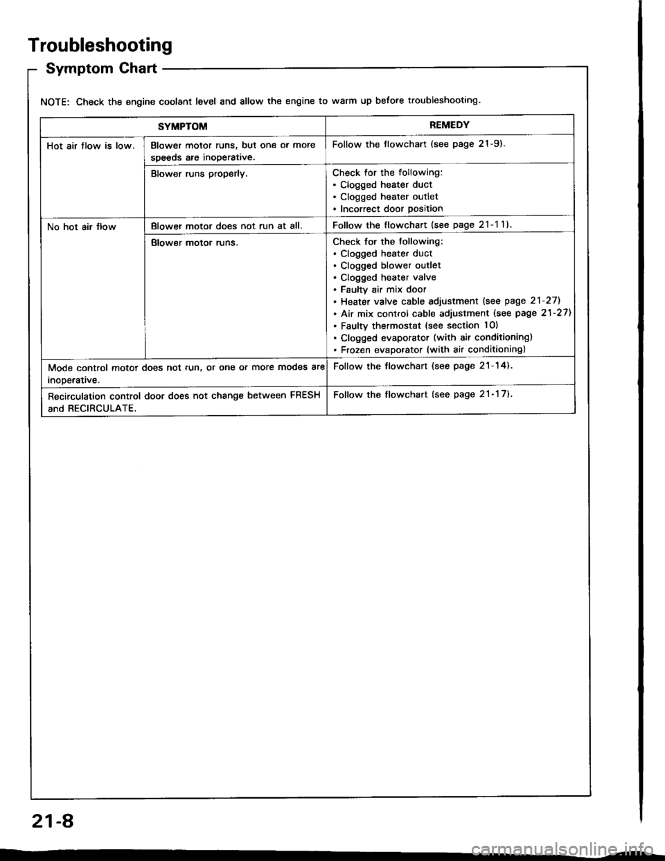
Troubleshooting
Symptom Chart
NOTE: Check the engine coolant level and allow the engine to warm up before troubleshooting.
SYMPTOMREMEDY
Hot air flow is low.Blower motor runs, but one ol more
speeds are inoperative.
Follow the tlowchart (see page 21-9).
Blower runs properly.Check for the following:. Clogged heater duct. Clogged heater outlet. Incorrect door position
No hot air JlowBlowel motor does not run at all.Follow the flowchart (see page 2l-l1l
Blower motor runs.Check for the following:. clogged heatet duct. Clogged blower outlet. Clogged heater valve. Faultv air mix door. Heater valve cable sdjustment lsee page 2'l-271
. Air mix control cable adjustment (see page 21-27)
. Faulty thermostat (see section lO)
. Clogged evaporator (with air conditioning). Frozen evaporator (with air conditioning)
Mode control motor does not run, or one or more modes are
inooerative.
Follow the flowchart (see page 21-14).
Recirculation control door does not change between FRESH
and RECIRCULATE.
Follow the flowchart (see page 21- 17).
21-A
Page 1057 of 1413

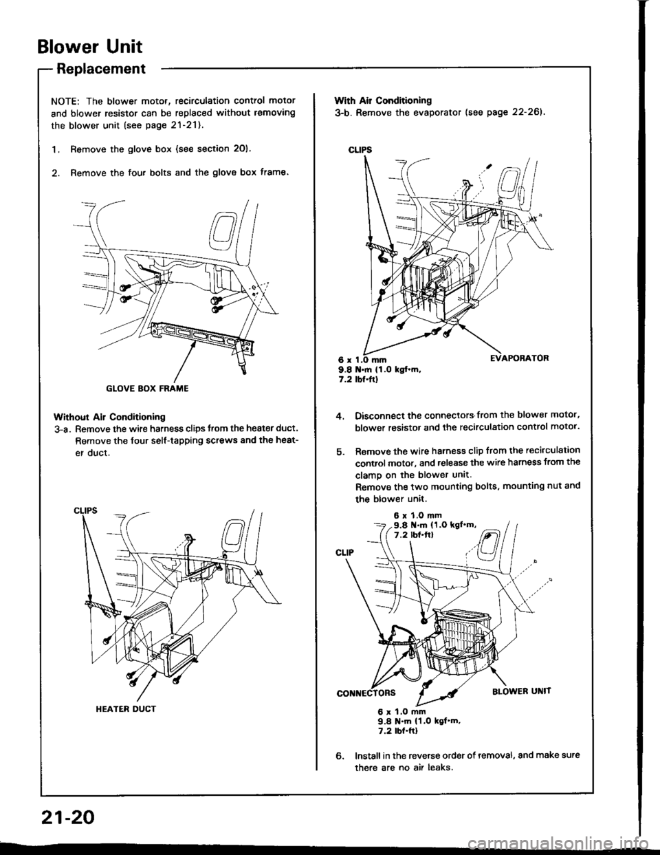
Blower Unit
Replacement
NOTE: The blower motor, recirculation control motor
and blower resistor can be replaced without lemoving
the blower unit (see page 2l-21).
1. Remove the glove box (see section 2O),
2. Remove the fou. bolts and the glove box frame.
Without Ail Conditioning
3-a. Remove the wire harness clips trom the heat€r duct.
Remove the Jour self-tapping screws 8nd the heat-
er duct.
GLOVE BOX FRAME
HEATER DUCT
With Air Conditioning
3-b. Remove the evaporator (see page 22-261.
CLIPS
6x I9.8 .ft 11.O kgt.m,7.2 tbt.ftl
4.
6.
Oisconnect the connectors from the blower motor,
blower resistor and the recirculation control motor.
Remove the wire harness clip from the recirculation
control motor, and release the wire harness from the
clamo on the blower unit.
Remove the two mounting bolts, mounting nut and
the blower unit,
6 x 1.0 mm
6 x 1.O mm9.8 N'm (1.0 kgf'm.7.2 tbt.ftl
lnstall in the reverse order of removal, and make sure
there are no air leaks.
9.8 .m (1.O kgl'm,7.2 lbf'ft}
21-20
--