Page 1018 of 1413
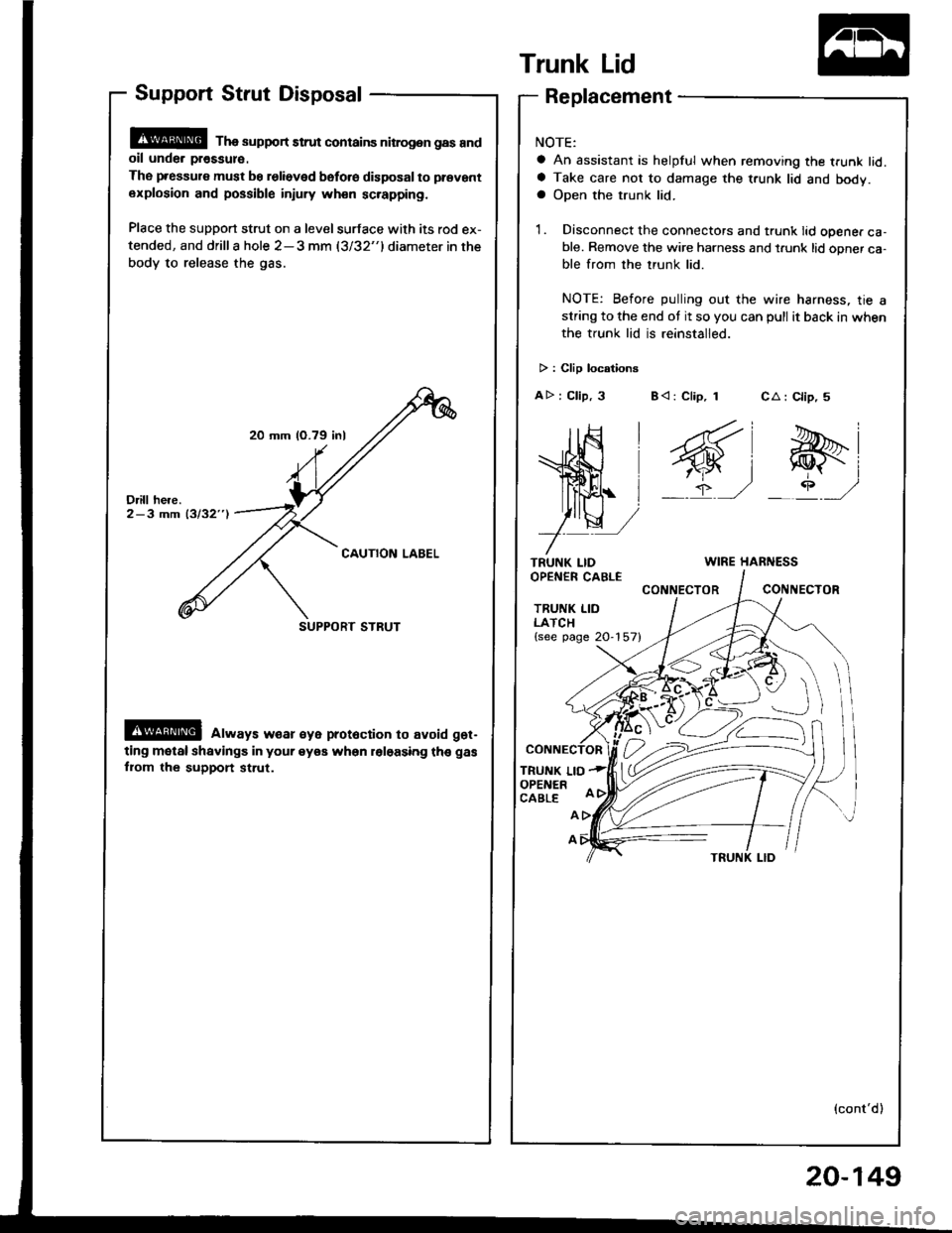
20 mm (O.79 inl
SUPPORT STRUT
Support Strut Disposal
@ Tha support strut contains nitrog.n gas andoil unde. pr€ssul€.
The pressure must be relieved bsfo.e disposal to prevant
explosion and possible injury wh€n sc.apping.
Place the support strut on a level surface with its rod ex-
tended, and drilla hole 2-3 mm (3/32"1diameter in the
body to release the gas.
@ always w€ar €ye prot6ction to avoid get-
ting motal shavings in your eyea when roloasing th€ gas
fiom the support st.ut.
Trunk Lid
TRUNK LIDOPEN€R CABLE
TRUNK LIDLATCH{see page 20-157}
TRUNK LIOOPENERCABLE
CA : Clip, 5
e-i
_rP ,/
Replacement
NOTE:
a An assistant is helpful when removing the trunk lid.a Take care not to damage the t.unk lid and body.a Open the trunk lid.
1. Disconnect the connectors and trunk lid opener ca-ble. Remove the wire harness and t.unk lid opner ca-ble from the trunk lid.
NOTE: Before pulling out the wire harness, tie astring to the end ot it so you can pull it back in when
the trunk lid is reinstalled.
> : Clip locationg
AD : Clip, 3 B< : Clip, 1
WIRE HARNESS
CONNECTORCONIIECTOR
A
A
(cont'd)
20-149
Page 1039 of 1413
lllustrated Index
CAUTION:
a All SRS electrical wiling harnesses are covered with
y€llow insulation.
a Bafore disconnecting any pan of the SRS wile har-
ness. connect the sholt connectorlsl.
a Replace the sntire aflected SRS halness assembly if
it has an open circuit or damaged wiring.
NOTE: The original radio has a coded thelt protection
circuit. Be sure to get the customer's code number before- disconnecting the battery.- removing the No. 32 (7.5 Al fuse lrom the under-
hood fuse/relav box.- removing the radio.
After service, reconnect power to the radio and turn it
on. when the word "CODE" is displayed, enter the cus-
tomer's 5-digit code to restore radio operation.
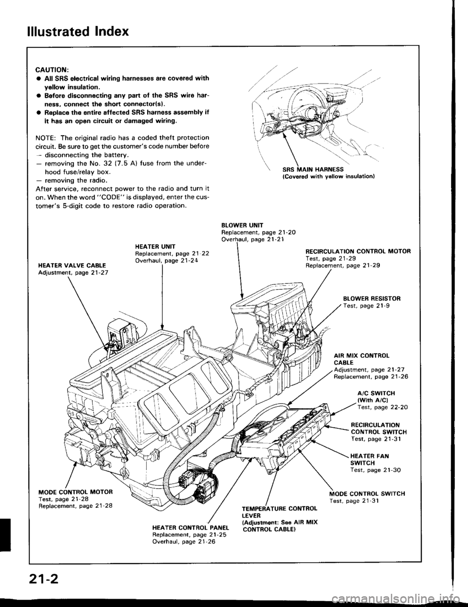
BLOWER UNITReplacement, page 21-2OOverhaul, page 21-21HEATER UNITRepfacement, page 2l 22Overhaul, page 21-24
RECIRCULATION CONTROL MOTORTest, page 21-29Replacement, page 21 29I{EATER VAIVE CABLEAdjustment, page 21-27
BLOWEN RESISTORTest, page 21-9
AIR MIX CONTROLCABLEAd,ustment, page 21-27Replacement. page 21-26
a/c swrTcH(wirh A/clTest, page 22-20
RECIRCULATIONCONTROL SWITCHTest, page 21-31
HEATER FANswtTcHTest, page 2'l-3O
MODE CONTROL MOTORTest, page 21-28Repfacement, page 21'28
MODE CONTROL SWITCHTest, page 21'31
HEATER CONTROL PANELRepf acement, page 21 -25
Overhaul, page 21-26
TEMPERATURE CONTROLLEVER(Adjustmonl: See AIR MIXCONTROL CABLE}
SRS MAIN HARNESS
W,
21-2
I
Page 1057 of 1413
Blower Unit
Replacement
NOTE: The blower motor, recirculation control motor
and blower resistor can be replaced without lemoving
the blower unit (see page 2l-21).
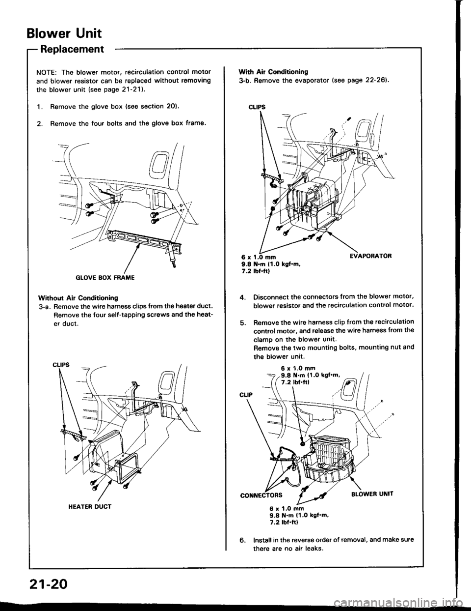
1. Remove the glove box (see section 2O),
2. Remove the fou. bolts and the glove box frame.
Without Ail Conditioning
3-a. Remove the wire harness clips trom the heat€r duct.
Remove the Jour self-tapping screws 8nd the heat-
er duct.
GLOVE BOX FRAME
HEATER DUCT
With Air Conditioning
3-b. Remove the evaporator (see page 22-261.
CLIPS
6x I9.8 .ft 11.O kgt.m,7.2 tbt.ftl
4.
6.
Oisconnect the connectors from the blower motor,
blower resistor and the recirculation control motor.
Remove the wire harness clip from the recirculation
control motor, and release the wire harness from the
clamo on the blower unit.
Remove the two mounting bolts, mounting nut and
the blower unit,
6 x 1.0 mm
6 x 1.O mm9.8 N'm (1.0 kgf'm.7.2 tbt.ftl
lnstall in the reverse order of removal, and make sure
there are no air leaks.
9.8 .m (1.O kgl'm,7.2 lbf'ft}
21-20
--
Page 1060 of 1413
5.
6.
7.
Rsmove the dashboard (see section 2O).
Remove the heater duct (see page 21-20) or theevaporator lse€ page 22-26).
Rsmove the two bolts, nut and the passenger,s SRS(}eam.
PASSEIVGER'SSRS EEAM
Disconnect the mode control motor conngctor, andremove the wire harness clip from the h€8ter unit.Remove the two mounting nuts and the haater unit.
6 r 1.0 mm9.8 .m (l.O kgt.m, 7.2 tbt.frl
MODE COI{TROL I,IOTORcol{t{€cToF
8.
8 x 1,26 mln22 N.m 12.2 kgf.m, 18 tbt.ttl
9. Install in the reverse order of removal, and:
a apply sealant to the grommets.a do not int6rchange the inlet and outl€t hoses.Make sure that the hose clamps are secure.a loosen th€ ble6d bolt on th6 engine and r€fillthetadiator and coolant r€servoir with the propsr en_gine coolant mixture (sse section 1O).Tighten the blsed boh when all the trapped air has6sc8p6d and engine coolant begins to flow fromit (see section 1O).a connect all csbles and make sure they 8re properlyadiusted (see pdge 21-271.
21-23
Page 1066 of 1413
Recirculation Control Motor
Test
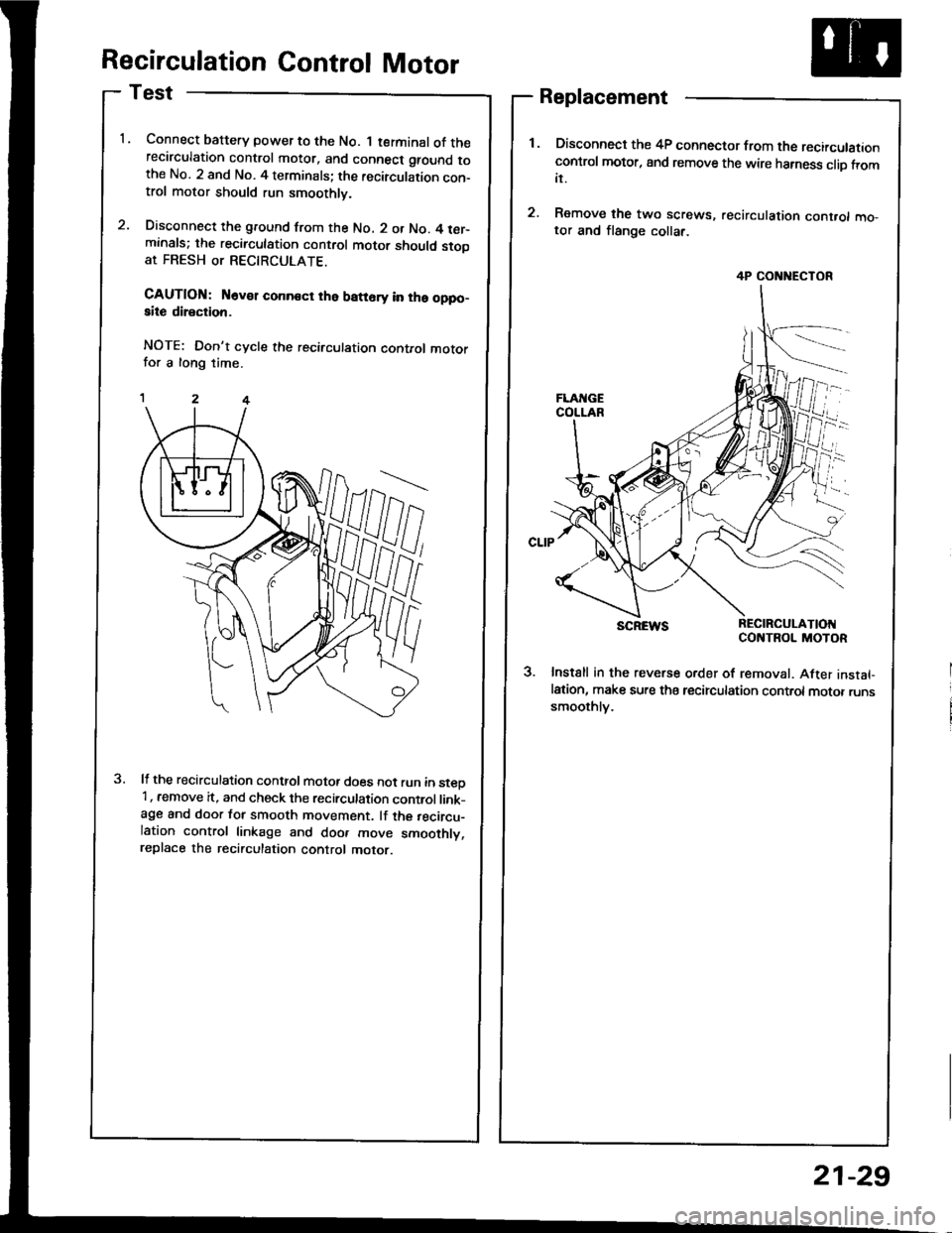
Connect baftery power to the No. 1 terminal of therecirculation control motor, and connect ground tothe No. 2 and No. 4 terminals; the recirculation con-trol motor should run smoothly.
Disconnect the ground from the No. 2 or No. 4 ter-minals; the recirculation control motor should stooat FRESH or RECTRCULATE.
CAUTION: N6v€r conn€ct the batt6ry in ths oppo-aite direction.
NOTE: Don't cycle the recirculation control motorfor a long time.
It the recirculation conttol motot does not run in steD'1, remove it, and check the recirculation control link-age and door for smooth movement. lf the recircu-lation control linkage and doo. move smoothly,replace the recirculation control motor.
Replacement
Disconnect the 4P connector from the recirculationcontrol motor, and remove the wire harness clio fromit.
Remove the two screws, recirculation cont.ol mo,tor and flange collar.
SCREWS REC|RCULAT|OIICONTROL MOTOR
3. Instsll in the reverse order of removal. After instal-lation, make sure tha tecirculation control motor runssmoothlv.
4P CONNECTOR
21-29
Page 1070 of 1413
Special Tools
Ref. No. I Tool Numbel
Test Harness
Belt Tension GaugeOTLAJ - PT3O1OA
07JGG - 001010A
I
22-2
Page 1071 of 1413
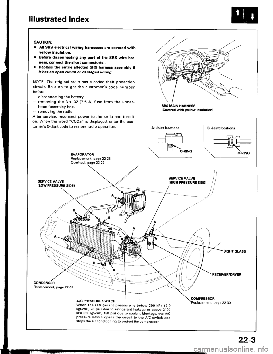
lllustrated Index
CAUTION:
. All SRS electrical wiring harnossos are cover€d withyellow insulation.
. B€fors disconnacting any part of the SRS wire har-ness, connsct the 3hort connsctor(s).. Replace the entirs affscted SRS harness assembly itit has an open circuit or damaged wiring.
NOTE; The original radio has a coded theft protection
circuit. Be sure to get the customer's code number
before- disconnecting the battery.- removing the No.32 (7.5 A) fuse from the under-
hood fuse/relay box.- removing the radio.
After service, reconnect Dower to the radio and turn it
on. When the word "CODE" is displayed, enter the cus-
tomer's 5-digit code to restore radio operation.
SRS MAIN HARNESSlcover€d with yellow insulationl
EVAPORATORReplacement, page 22-26Ovethaul. Oase 22.27
SERVICE VALVE(LOW PRESSURE SIDEI
SERVICE VALVEIHIGH PRESSURE SIDE)
RECEIVER/DRYER
CONDENSERReplacement, page 22,37
A/C PRESSURE SWITCHCOMPRESSORReplacement, page 22-30When the refrigerant pressure is below 200 kpa (2.0kqflcm,,28 psi) due to refrigerant leakage or above 3]OOkPa (32 kgf/cm,, 460 psi) due to coolant btockage, the A,/Cpressure switch opens the circuit to the A"/C switch andstops the air conditionang to protect the compressor.
22-3
Page 1072 of 1413
Wiring/Connector Locations
A/C DIODECONNECTOR(Loc.ted .bovo tho.ight kick p.n.ll
RADIA'OR FAN RELAY{Localed in the undel-hood fu3o/reltY box)
A/CTHERMOSTAT CONDENSERFANCONNECTOR CONNECTOR
MAIN WIRE HARNESS
A/C WIRE HARNESSCONNECTOR
RADIATOR FANCONNECTOR
A/C WIRE HARNESS
COMPRESSOR CLUTCHCONNECTORA/C PR€SSURE SWTTCHCONNECTOR
22-4