Page 1000 of 1413

Dashboard
Component Removal/lnstallation
SRS wire harnesses are routed near the dashboard andsteering column.
CAUTION:
a All SRS olectrical wiring harnesses ar6 covolodwith yallow insulation.
a Betoro disconnecting any paft ot th6 SRS wiro
harn€ss, connoct th€ shoi connectots (s66 page
23-2721.
a Replaco th€ entire Itlocted SRS hsrness asaem-
bly il h has an open circuh or damagod wiring.
CAUTION: Whan prying with a flat tip scrowdiv... wrapit with protoctiv€ tape, and apply protectivo tapo a.oundth€ felatsd parts. to provent damag€.
Instiumont p8n6l, Dashboad lower covor. Knec bobtcframoval:
l. Lower the steering column.
2. Remove the screws and detach the cliDs, then re-
move the instrument panel.
3. Remove the coin oocket.
4. Remove the screws and detach the clips, then re-
move the dashboard lower cover.
Disconnect the connector.
: Scrawlocation3, 5
AIF|]A\g)
A i Clip locationg
AA: Cllp, 2 B> : Clip, 2
I l-l L'l| ,-__-, )
itrvi
) 4Z)
_:n,,4<-ft
INSTRUMENT PAI{EL
(cont'd)
COIN POCKET
20-131
Page 1002 of 1413
4. Remove the screws.
Detach the harness clip and connector clip.
> : Screw locations, 2
Disconnect the air mix control cable from the heat-
er unrt.
AIR MIX CONTROLCABLE
AIR MIX CONTROL
CONNECTOR CLIP
HEATER CONTROL
CABLE
20-133
Pull the heater control panel out, then disco.rEt rhGconneclors.
NOTE: Take care not to bend the atr mtx controlcable.
AIR MIX COI{TROLCABLE
HEATERCONTROIPANEL
7, lnstallation is the reverse o{ the removal procedure.
NOTE: Make sure the connector and air mix con-trol cable are connected properly.
(cont'd)
Page 1005 of 1413

Dashboard
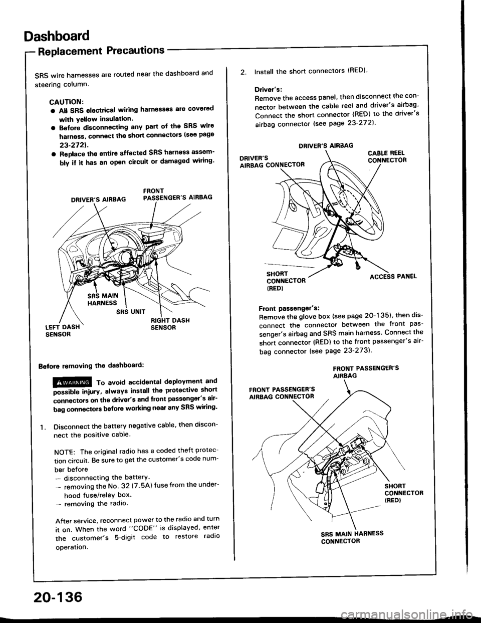
Replacement Precautions
SRS wife harnesses are routed near the dashboard and
steering column.
CAUTION:
a Alt SRS olectrical wiling harness€s ale covorad
with Yollow insulation.
a Botore disconnecting any part ot the SRS wiro
harness, connect ths short connscto6 (see page
23-2721.
a Roplac6 ih€ entiro aflectod SRS halnoss assem-
bly il it has an opon cilcuit or damagod wiling'
LEFT DASHSENSOR
Bstora lomoving the dashboaid:
!@@ To avord accioenlal dsployment and
""iUU inir.v, always install the plotoctive short
;onnectors on the driver's and tlont pass€ngel's air-
bag connectors bolors working near any SRS wiring'
1. Disconnect the battery negative cable, then discon-
necl the positive cable.
NOTE: The original radio has a coded theft protec
tion circuit. Be sure to get the customer's code num-
ber before- disconnecting the battery.
- removing the No 32 (7.5A) Iuse from the under-
hood fuse/relaY box'- removing the radio.
After service, reconnect power to the radio and turn
it on. When the word "CODE" is displayed, enter
the customer's 5 digit code to restore radlo
ooeration.
DRIVER'S AIREAG
SRS UNIT
20-136
DRIVER'S AIRBAG
2.lnstall the short connectors (RED)
Ddvar's:
Remove the access panel, then disconnect the con-
nector between the cable reel and driver's airbag'
Connect the short connector (RED) to the driver's
airbag connector lsee page 23-27 2l'
DRIVER'SAIRBAG CONNECTOB
CABLE REELCONNECTOR
SHORTCONNECTOR(RED)
Front passongor's:
Remove the glove box {see page 20-135}, then dis-
connect the connector between the tront pas'
senger's airbag and SRS main harness Connect the
short connector (RED) to the front passenger's air-
bag connector (see Page 23-273).
FROf{T PASSENGER'SAIRBAG
ACCESS PAI{EL
FRONT PASSET{GER'SAIRBAG CONNECTON
SHORTCONNECTOR(REDI
SBS MAIN HARNESS
CONNECTOR
Page 1006 of 1413

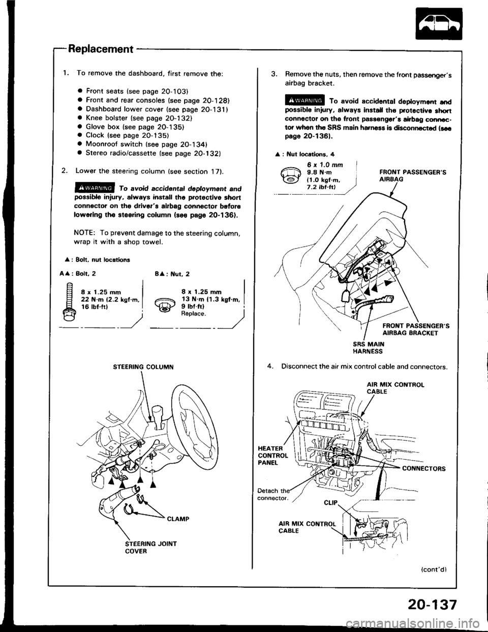
Replacement
To remove the dashboard, first remove the:
a Front seats (see page 2O-103)
a Front and rear consoles (see page 20-128)a Dashboard lower cover (see page 2O-131)a Knee bolster (see page 2O-132)a Glove box lsee page 2O-135). Clock (see page 20-135)
a Moonroot switch (see page 20-1341a Stereo radio/cassette {see page 20-132)
Lower the steering column (see section 17).
@@ ro avoid accidentat dedoyment andpossiblo in ury, always install the prot€ctive short
connector on tho drivsr's airbag connector bgtor€
lowering tho stooring column (so€ page 20-1361.
NOTE: To prevent damage to the steering column,
wrap it with a shoD towel.
: 8olt, nul locations
A
: Bolt, 28 : ut, 2
8 x 1.25 mm22 N-m 12.2 ksl.m,16 lbt.frl
8 x 1.25 mm
gill$"'l
STEERING COLUMN
3. Remove the nuts, then remove the front passsnger,s
airbag bracket,
@ To avoid accidantar daploym.nr ",'dpossibls iniury, always install th€ protoctiv. 3hqtconnoctor on tho ,ront passongor'a airbag conncc-tor whon tha SRS main ha.na$ is disconncctod llcrpago 20-136).
: Nut locatlons, 4
FRONT PASSENGER'S
FRONT PASSENGER'SAIRBAG BRACKET
4.
SRS MAINHARNESS
Disconnect the air mix controlcable and connectors.
AIR MIX CONTROLCAELE
CONNECTORS
(cont'dl
20-137
Page 1007 of 1413

Dashboard
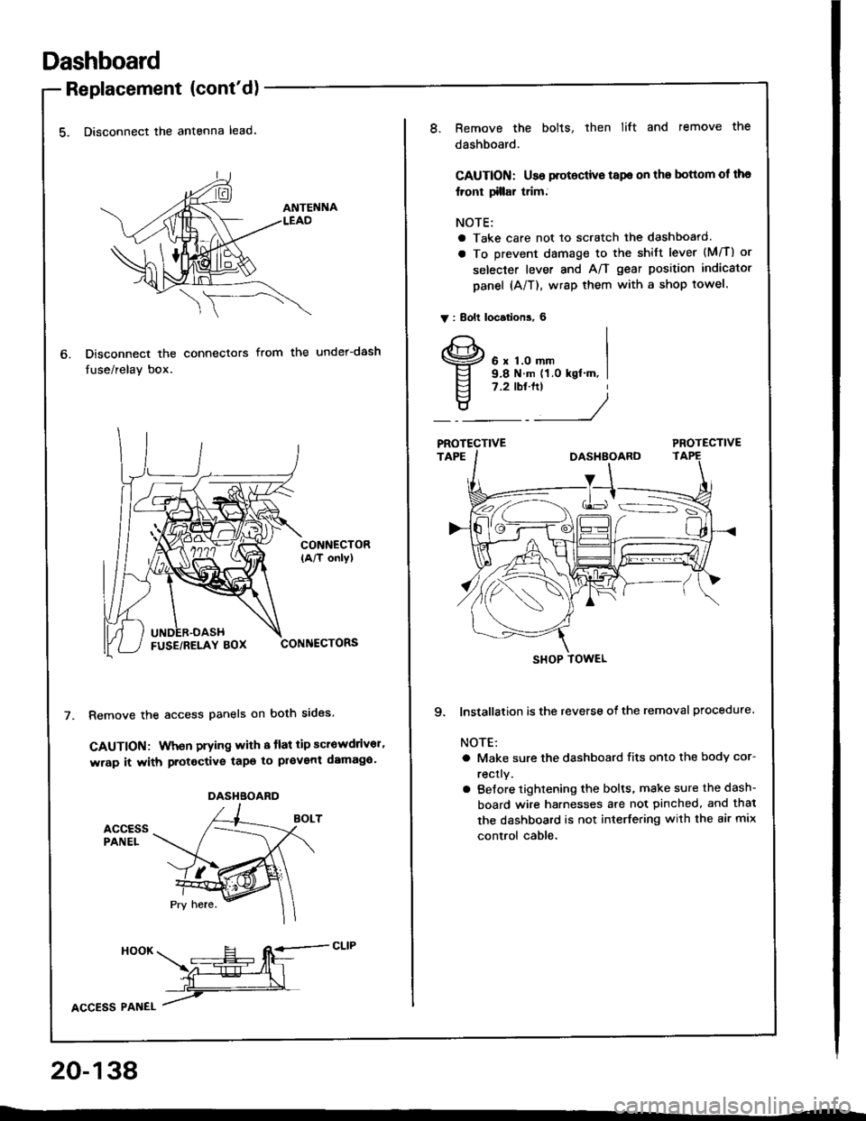
Replacement (cont'd)
5. Disconnect the antenna lead.
Disconnect the connectors
fuse/relay box.
from the under-dash
CONNECTOR(A/T only)
CONNECTORS
Remove the access panels on both sides.
GAUTION: When prying with 8 tlat tip scrowdrivor'
wrap it with protective tapo to pl€vent damaga'
accEssPANEL
6.
DASHBOARD
HooK ___E-- RE=-cLrP
ffiL
lcCesS Plnel /
20-138
8.Remove the bolts, then lift and remove the
dashboard.
CAUTION: Use protoctive tspe on the bottom ol tha
lront tillar trim;
NOTE:
a Take care not to scratch the dashboard.
a To prevent damage to the shift lever (M/T) or
selecter lever and A/T gear position indicator
panel (A/T), wrap them with a shop towel.
V : Bolt locations, 6
6 x 1.0 mm9.8 N.m (1.0 kgt'm, I7.2 tbt.ftt
____/
PROTECTIVE
9. lnstallation is the reverse of the removal procedure
NOTE:
a Make sure the dashboard fits onto the body cor-
rectly.
a Before tightening the bolts, make sure the dash-
board wire harnesses are not pinched, and thal
the dashboard is not interfering with the air mix
control cable.
SHOP TOWEL
Page 1010 of 1413
Rear Bumper Replacement
NOTE:
a An assjstant is helpful when femoving the rear bum-per and rear bumper beam.
a Take care not to scratch the rear bumper.
Hatchback
1. Remove the screw from each side.
REAR BUMPER
Open the hatch, then remove the rear trim panel (see
page 20-921-
Remove the nuts, and disconnect the license plate
light connector and grommet.
Scrow I
A
A\
:
J.
> : Nut locotions, 4
/ 6x1.Omm I
Q) i;L'i$-. l
_':'y:) ,/BIGHT SIDETRIM PANEL
To remove the nuts, remove the rearportion of the side trim panel oneach slde {see page 20-921.
LEFT S|DE L|CENSE PLATE LtcHT
4. Remove the bolts, then remove the rear bumper.
: Bolt locations, 2
5. lf necessary, remove the bumper upper beam from
the rear bumper.
: Screw locotions
A : Scr€w, 4 B <: Sc.ow, 4 V: Clip locations, I
REAR BUMPER
--E- I
.--r-Fl^ |--lEr-
_\"., J
^i
@sl
_'/
LICENSE PI-ATELIGHT HARNESS
(cont'd)
REAR BUMPER
20-141
Page 1012 of 1413
4. lf necessary, remove the license plate light harness,bracket and lens from the rear bumper (see page20-1411.
5. Remove the absorb€r, bumper beam gusset and fearbumper beam.
V i Bolt locatlons, 4
REAR BUMPERBEAM
BUMPER BEAMGUSSET
12 x 1.25 mm64 .m (6.5 kgf47 tbt.ftl
I.m, j
)
6. Installation is the .everse of the removal procedure.
NOTE:
a Make sure the license plate light connector is con-
nected, and the grommet is installed properly.
a Make sure the rear bumper engages the side clips
securelv.
REAR BUMPER
20-143
Page 1015 of 1413

Hatch
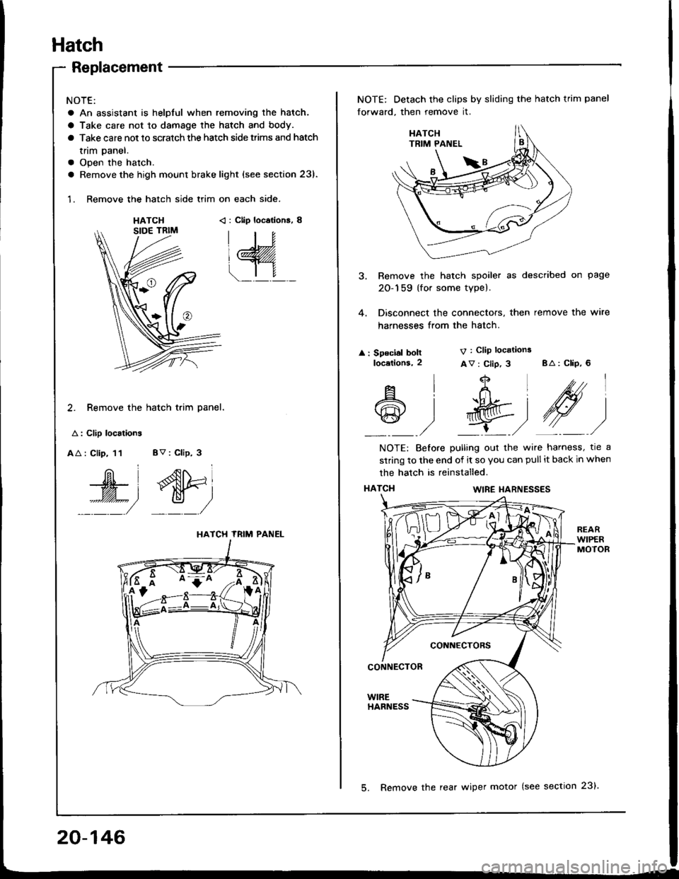
Replacement
NOTE:
a An assistant is helpful when removing the hatch.
a Take care not to damage the hatch and body.
a Take care not to scratch the hatch side trims and hatch
tnm paner.
a Open the hatch.
a Remove the high mount brake light {see section 23).
1. Remove the hatch side trim on each side.
HATCH< : Clip locations, 8
2. Remove the hatch trim panel.
A : Clip localions
AA : Clip, 11 BV : Clip, 3
W', dtri
::::/ _:_/
HATCH TRIM PANEL
NOTE: Detach the clips by sliding the hatch trim panel
forward, then remove it.
3. Remove the hatch spoiler as described on page
20-159 (for some type).
4. Disconnect the connectors, then remove the wire
harnesses from the hatch.
: Speclal boltlocetlons,2
V : Clip locations
Av : Clip, 3 BA: CliP, 6
4
t+Ltfrl
l'R@t
,/ L,/
A
@
l
)
NOTE: Before pulling out the wire harness, tre a
strinq to the end of it so you can pull it back in when
the hatch is reinstalled.
HATCI{WIRE I{ARNESSES
CONNECTORS
CONNECTOR
WIREHARNESS
20-146
5. Remove the rear wiper motor (see section 23).