Page 465 of 1413
S.fdl.enorl! L&l indicdor lighlblinks fourtoon tlmoa.
ls the Malfunction IndicatorLamp (MlL) onl
Stan the ongine and warm it upto normal operating temperature{th€ radiator lan com€s on).
Shift to E position,
Turn rhe ignition switch OFF.
Possible Cause
. Sh"rt ". "e"" i" FAS |YEU ,"rirt. Fsulty ECM.
Connect the Test Harness be-tween the TCM and connociors{see page 14-491.
Turn the ignition switch ON andwsit for at least two seconds.
o oooooo ooo ooo l.tto.oodooo l:,gEoo.ottl o ooooo oooo o
o oooo oooooooo l:OOOO OO 60 l.,OO{tO.O6,'l o oooooooooo
Measure lhe voltage betwgan thso16l+ ) and A25 or A26(- | tor-mrnals.
lcont'd)
Ropair tho PGM-FI Syrtom lloo..ctlon 111.
Chock for looro TCM connoctora.lf noco$ary, subatituta a known-good TCM and .ech€ck.ls thoro approx. 5 V?
Turn the ignition switch OFF.
Dkconnect the Test Harness fromthe TcM.Leave connect€d to car harness.
Turn the ignition switch ON.
fo page 14-74
14-73
Page 466 of 1413

Electrical Troubleshooting
Troubleshooting Flowchart (cont'd)
ls there continuity?
o o o o o o o o O o O o O $:O.COOtt9O$:l:OtO:CtOiOi:l O o O O O O o O o o Oo o o o o o o o o o o o O I:f(O.{iltltO{t{t:I:OFA:F:d:O:l o o o o o o o O o o o
NOTE: View lrom wire side.
NO
From page 14-73
Measure the voltage between theD 16{+ ) and A25 or A26{- ) ter-mtnals.
Check for loos€ TCM connoctors.ll ngcossary, substituto a known-good TCM and rechock.
ls there approx. 5 V?
Disconnect the 26P connectorfrom the ECM.
Check for continuitv between theD16 and A25 or A26 rerminals ofthe Test Harness.
Ropairshort in YEL IFAS) wire be-tw6on TCM and ECM.
Disconnect the 26P and 22P con-nectors from the Test Harness.
Check for continuity between theD16 (YEL) terminal ot fCM 22Pconnector and A19 (YEL) terminalof ECM 26P connector.
Chgck tor loos€ TCM connoctofs.lf nocassary, substitute o known-good TCM and rech6ck.
Ropair opon in YEL {FAS} wiro bo-trve€n TCM and ECM.
oooooooooooo
oooooooooooo
ooooooooooo
ooooooooooo
22P CONNECTOB
Page 482 of 1413
Road Test
NOTE: Warm up the engine to operating temperature (the cooling fan comes on).
1 Apply parking brake and block th€ wheels. Start the engine, them move the selector lever to E] position whiledepressing the brake pedal. Depress the accelerator pedal, and release it suddenly. The engine should not stall,
2. Repeat same test in @ position.
3. Shift the selecto. lever to E position, and chock that the shift points occur at approximate speeds shown. Alsocheck fof abnormal noise and clutch slippage.
NOTE: Throttle position sensor voltage fepresents the throttle opening.
- 1 . Connect the Test Harness between the ECM and connector (see section 1 1).-2. Setthe digital multimeter to check voltage between D1 1{+)terminal and D22 { - ) terminal for the throttle Dosi-tion sensor.
TESTHARI{ESSOTLAJ_PT3OlOA
DIGITAL MULTIMETERCommarcially avsilablo o.KS-AHM-32-OO3
011 {+oooooooooooooooooooooooooooooooooooooooooooooooooooooooooooooooooooooooooooo
14-90
Page 1083 of 1413

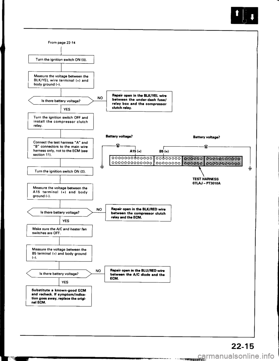
Frcm page 22-11
Bdt ry vohro.?
_@_____-l
Turn the ignition switch ON (lI).
M€asure the voltage betweon th6BLK/YEL wire terminsl {+) andbody ground (-).
R.p.i. opcn in th. 3LX/YEL wirrbalwarn tha undar.da3h tuaa/.clay box and iha como.aaao.clutch rahy.
ls there battery voltage?
Turn the ignition switch OFF andinstall the comprossor clutchrelay.
Connect the test harness "A" and"8" conoectors to th6 main wireharness only, not to the ECM (s6gsection 11).
Turn th6 ignition switch ON (II).
Measure the voltagG between theA15 terminal (+) and bodyground (-1.
R.prir op.n in th. BLK/RED wirtb.twran the compraa.or clotch..1.y .nd th. ECM.
Make sure the A/C and heate. tenswitch6s are OFF.
Measure tho voltage b€tween the85 terminsl (+) and body ground(-).
R.p.ir op.n in th. BI-U/RED wir.b.tw.rn th. A/C diod. .nd th.CCM.
Sub.titute r known-good ECMand rocheck. lt lymptom/indicr-tion go€3 rwry, rapbca th. origi-nrl ECM.
Blttary vohago?
r_--@_Bs {+)
TEST HARNESS07t4, - PT3010a
" , -1llltf,'tfrSfiiwiafi
22-15
Page 1115 of 1413
I
I
POWER DOOR LOCKCOI{TROL UNIT
ENGINE CONTROL MODULE(ECM}
ii.11r'
23-9
Page 1130 of 1413
Connector ldentification and Wire Harness Routing
Main Wire Ha.ness {Right branch}
Connactor or
Terminal
Numbsr of
Caviti€sLocationConnscts tottlotor
c401
c402
c403
c404
c405
c406
c407
c408
c409
c410
,E
10
2
22
lo
22
26
Front Passenger's door
Under right side of dash
Under right side ot dash
Under right side of dash
Under right side of dash
Under right side ot dash
Behind right kick panel
Behind right kick panel
Behind right kick panel
Behind right kick panel
Front passenger's door wire
harness (C626)
A/C diode
Heater sub-harness A (C672)
Heater sub-harness A {C671}
SCS short connectol
Data link connector (DLC)
ABS sub-harness (C7011
Engine control module (ECM)
Engine control module (ECM)
Engine control module (ECMI
23-24
Page 1155 of 1413

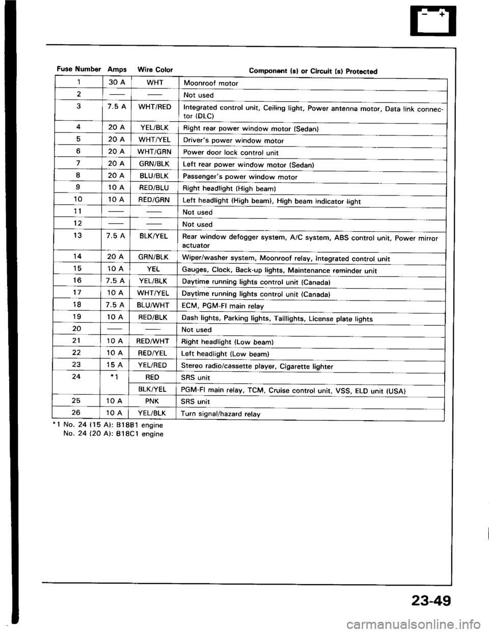
Fuse Numb€r AmDs Wire CololGomponent ls) or Circuit (s) Prot8cted
130AWHTMoonroof motor
2Not used
37.5 AWHT/REDIntegrated control unit, Ceiling light, Power antenna motor. Data link connec-tor (DLC)
420AYEL/BLKRight rea. power window motor (Sedan)
520AWHT/YELDriver's power window motor
o20AWHT/GRNPower door lock control unit
720AGRNiBLKLelt rear power window motor (Sedan)
I20ABLU/BLKPassenger's power window motor
I10 ARED/BLURight headlight {High beaml
1010 ARED/GRNLeft headlight (High beam). High beam indicato. tight
11Not used
12Not used
137.5 ABLK/YELRear window defogger system, A/C system, ABS control unit, power mrrroractuator
1420AGRN/BLKWiper/washer system, Moonroof relay, Integrated control unii'1510 AYELGauges, Clock, Back-up lights, Maintenance reminder unit
to7.5 AYEL/BLKDaytime running lights control unit (Canadal
1710 AWHT/YELDaytime running lights control unit (Csnada)
7.5 ABLU^tvHTECM, PGM-FI main relay'to10 ARED/BLKDash lights, Parking lights, Taillights, License plate tights
20Not used
2110 ARED/WHTRight headlight (Low beam)
10 ARED/YELLeft headlight (Low beam)
2315 AYEL/REDStereo radio/cassette player, Cigarette lighter
24REOSRS unit
BLK/YELPGM-FI main relay, TCM, Cruise controt unit, VSS, ELO unit IUSA)
2510 APNKSRS unit
2610 AYEL/BLKTurn signal/hazard relay'1 No.
No.
24 115 Al:
24 t2O At:.
81881 engine
B18Cl engine
23-49
Page 1158 of 1413
Fuses
Under-hood Fuse/Relay Box
ALTERI{ATOR
fTo .ngino wlto hsrno$ {Tlolll
Not usod
r: l\lot u3.d
umborAmpsColor
nF n nn46 45 /t4 35 3l
UU U UU
n32
U
n
33
U
r:rg
U
n
42
U
n43
U
[To rldidor hn r.l.Yl
Componon! (sl 01 Clrcuit 13) Protoqtod
3115 AYEL/WHTPGM-Fl main relay
327.5 AWHT/BLUECM, TCM. Clock, Stereo radio/cassette plsyer, Maintenance reminder unit
a2204BLK/REDRadiator Jan motor
34Not used
35204WHTCondenser fan motor, A/C compressor clutch
50AWHT/REDNo. I {3O A), No. 3 (7.5 A). No. 4l2O Al, No 5 (2O A), No. 7 (2O A),
No. I (20 A) fuses
3740ABLU/lVHTBlower motor
3830ABLK/GRNRear window defogger, Noise condenser
?q50AWHT/BLKlgnition switch {BAT}
4050AWHTCombination light switch, No. 17 (1O Al fuse
41100 APower distribution
4220AWHT/GRNHorn system, Brake system, Key interlock solenoid (Aff)
4310 AWHT/GRNTurn signal/hazard.elay
44Not used
45Not used
46Not used
23-52