Page 1160 of 1413
Power Distribution
L"I
.r"-
oiotG401
No.1l (100A)
UNOER-HOOD ABS FUSE/FEIAY 8OX
ABS 81 {2OA)
A86 82 II5AI
Gircuit ldentification
BATTERY
WHT/GRN f Bightr- blt) nas trom sotcooia
ABS oumo motor
8n /YEL - A8S contol unit
Btx/YEL < ib.l3 l7.5Al tu!.
YER/RED - A&S control unit
Stldar motorr BLKffEL
_o_:UNDER - HOOD FUSE/RELAY 8OX
No.43ll0Al
no.42 l20A)
wHT/GRt{ - Turn si0nrl/h.z.rd |thY
WHT/GRN
AL]ERNATOR I
tlomllom mLyKey intodock lohnokl {A/TlECMCruiso control unilTran.mksion control modub (TcMl
ABS contiol unh&6k lighl!
{To psge 23 - 55)
23-54
GRi{/REo - ECM
Page 1163 of 1413
IGNITION SWTCH ISTIlFrom p.!€ 23 - 561
f7
I.---F-------lI-lSTARTFPi Bffi,!'HT 6u?'ili,iY i| -' r r l clurcr It-11iPt ;rui8rr H inl-rhicicxswrcr 1,,,,,,Itill-+{ .'.i o-F BIK/RED --.5 BLX/!\,HT - st.der sotenoid il-l I r
BLK/REO
fr
r---
uxrivn Sr$!gfr*,r.,
L€-eumoBLKMHT - Starlsr solenoki
-------J
UNDER -DASH FUSEiRELAY BOX
No.l817.5A)ELUMHT --?- PGM _ Ft msin rctay- ECM
lnt€gretod control unit
St6r6o radio/c$r€tt6 playot
Cig€rone lightor
Option connoctor: C927
Pow6r minor *tuetols
noar wandow dologgor switchindicrtor light
R6dietor fan robyElowor motor rclayfuC compr$sor clutch rsl6yA/C lhomGtstCond6ns& tan ml6yMod6 control motorRocicubtion control motorH6at€r control panolRear window deloggor relayABS pomp motor tolayABS insp€ction connoctorABS contrcl unit
Option connoctor:C925
Daytime running lightscontrolunit
(From pag623-56 )
No.23ll5AlYEURED --E
lG2lFrom p.!623- 56 ){Fus€/relay box sockotl
+ l,lo,16 {7.5A1
23-57
Page 1166 of 1413
Ground Distribution
Gircuit ldentification
_d_:
GI
Blttory
Tnnll|iltirn houinc
Xmct t rmr l(Sl{VTEC}
lLatad orvo.n!.ruor lHozsl
Cnnkd|rft Dorition tICKPI$nlor t
ITDC !.No. t
Cylndar oolitirn fICYPI!.ir.o. 1
Mdn httt !p6od..n.or lAlTl
Co(||llanhrft !p.€dr.Bor WT)
_d_:
G3
Et - Y€||tr rpo€o llrEor rYSq- VrEC Dlaaaura rwitch18 | 8C l.r{i|r)
Engino coohnt tomporlru|! ICCTI!wilch
ux _r]---..o eu {l{ "-
E iTl*;,,
*" ",
L-----------
Dlt linl conn ctor lDl"ClI Tranamildrfi control dbduht (TcMt
ECM (-G ECM ILG2I
ECM
on[/8LU -r-.IWHT/BI-U+IsLu/GRN -FIBLUrYEL -
E: Irn ry oround cebh E , E tgi," *ir" ha."o
E: Enoina 0oond crbL A E , E tgir. *rp"nn"nt *ir. han*"s
E | €ngino ground c.bL 8 E: Mdn wirb hem6r
23-60
Tnnln&don codaol moduLfrcMt
Page 1182 of 1413

Starting System
Startel Test
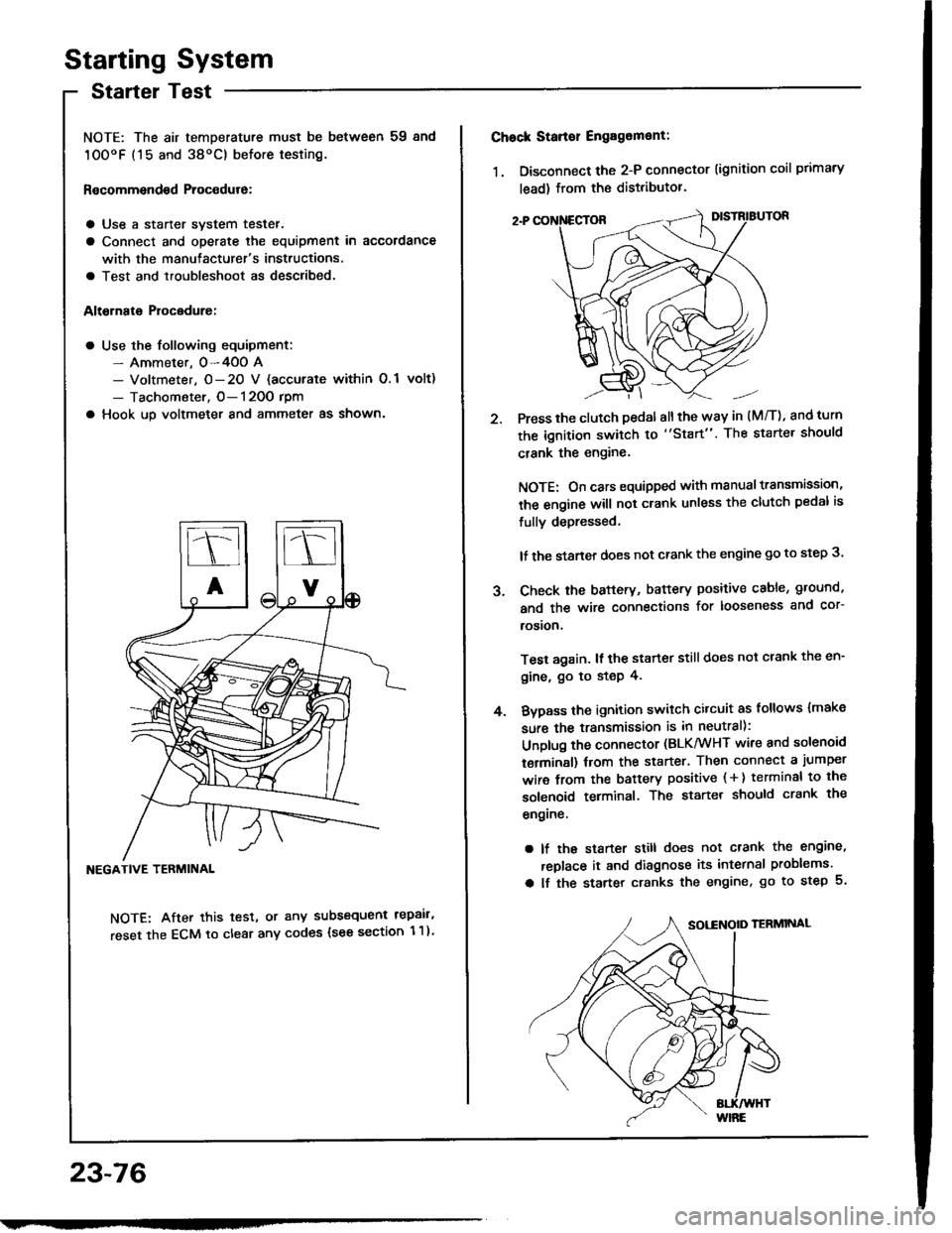
NOTE: The air temDerature must be between 59 8nd
10OoF (15 and 38oC) before testing.
Recommendsd Procodure:
a Use a staner svstem tester.
a Connect and operate the equipment in accordance
with the manutacturer's instructions.
a Test and troubleshoot as described.
Altohato Procedure:
a Use the following equipment:- Ammeter. 0-4OO A- Voltmeter, O- 20 V {accurate within 0.1 volt)
- Tachometer, O- 120O rpm
a Hook up voltmeter and ammeter as shown'
NEGATIVE TERMINAL
NOTE: After this test, or any subsequent repair,
reset the ECM to clear any codes (see section 1 1)
23-76
2.
Chock Stan€r Engag6ment:
1. Disconnect the 2-P connector (ignition coil primary
lead) from the distributor.
Press the clutch pedal allthe way in (M/T), and turn
the ignition switch to "Start". The starter should
crank the engine.
NOTE: On cars equipped with manual transmission,
the engine will not crank unless the clutch pedal is
fully depressed.
lf the staner does not crank the engine go to step 3.
Check the baftery, battery positive cable, ground,
and the wire connections for looseness and cor-
rosion,
Test again. lf the starter still does not crank the en-
gine, go to step 4.
Bvpass the ignition switch citcuit as follows {make
sure the transmission is in neutral):
Unplug the connector (BLK/WHT wire and solenoid
terminsl) trom the starter. Then connect a jumper
wire from the battery positive ( + ) terminal to the
solenoid terminal. The starter should crank the
engrne.
a lf the starter still does not crank the engine,
replace it and diagnose its internal problems.
a lf the starter cranks the engine, go to step 5.
J.
4.
Page 1194 of 1413
lgnition System
Circuit Diagram
CKP: Cr6nk.halt posilioo sonsorCYP| Cylindor position s€nsor
TOC/CKP/CYP SENSOR
-_r_1=__E
-J---L--L--Lr
ORN
U'+++
UNOER- HOOO FUSE/RELAY BOX
ECM
V
I
YEUGNiI
tG tTtoN c0NTROl-MoDUr.r (cMl
/ H8s built - in \I OOrsO I
23-88
Page 1202 of 1413

lgnition
lgnition
System
Control Module (lCMl Input Test
NOTE:
a See section I 1 if the malfunction indicator lamD (MlL)
blinks.
a Pertorm an input test for the ignition control module
(lCM) after finishing the fundamental tests for the ig-
nition system and the fuel and emissions systems.
a The tachometer should operate normally.
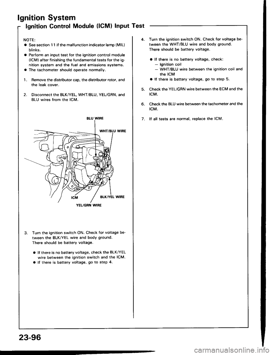
1. Remove the distributor cap, the distributor rotor, and
the leak cover.
2. Disconnect the BLK/YEL, WHT/BLU, YEL/GRN, and
BLU wires from the lCM.
3. Turn the ignition switch ON. Check for voltage be-
tween the BLK/YEL wire and body ground.
There should be battery voltage.
a lf there is no battery voltage, check the BLK^/EL
wire between the ignition switch and the lCM.
a lf there is battery voltage, go to step 4.
YEL/GRN wlRE
4.Turn the ignition switch ON. Check for voltage be-
tween the WHT/BLU wire and body ground.
There should be battery voltage.
a lf there is no battery voltage, check:- lgnition coil- WHT/BLU wire between the ignition coil and
the ICM
a lf there is battery voltage. go to step 5.
Check the YEL/GRN wire between the ECM and the
tcM.
Check the BLU wi.e between the tachometer and the
rcM.
It all tests are normal, replace the lCM.
6.
7.
23-96
Page 1205 of 1413
Circuit Diagram
UI,IDER - HOOD FUS€/REI.AY 8OX
*1 :USA+2 llo.24 ll SAl: 81881 .mintlo.24 {2041: 818C | .niin6
. NTEGRATEDCOMTNOL UMT. aBs coilTRor- uNn
VI
I
ECM
V
I
I
UNDER_OASHFUSE/REIAY 8OX
oiotG401
No.4t 11004) /a ilo.39l50Al
Fr€|'l) wNort'lc
AI.TERNATOR
23-99
Page 1206 of 1413

Charging System
Troubleshooting
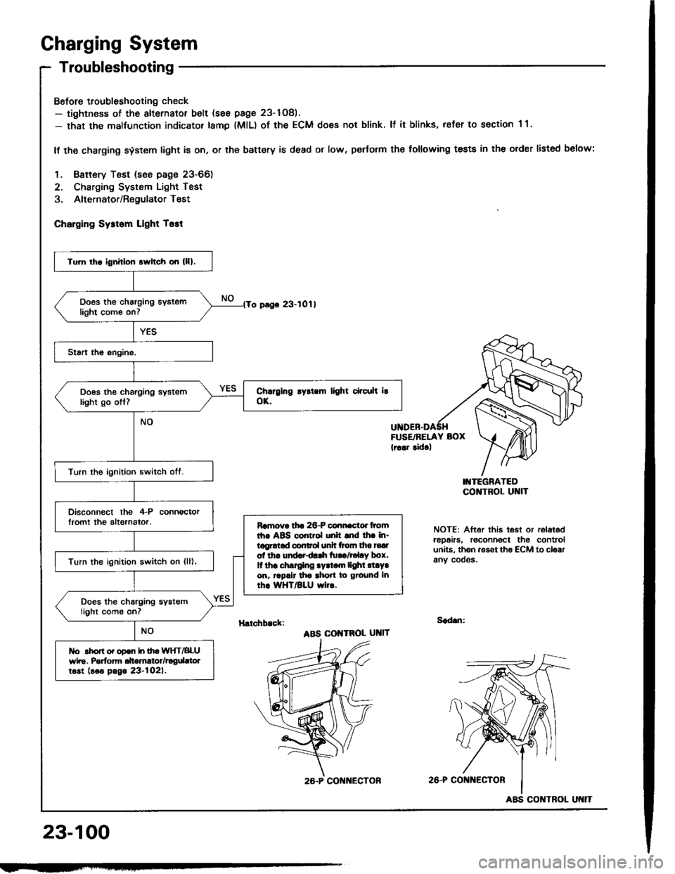
Bofore troubleshooting check- tightness of the alternator belt (see page 23-1Og).- that the malfunction indicator tamp lMlL) of the ECM does not blink. lf it blinks, refer to section 1 1.
lf the charging system light is on, or th€ battery is dead or low, p€rtorm the following tests in the order listed below:
1. Baftery Test (see page 23-66)
2. Charging System Light Test
3. Alternator/RegulatorTest
ChErging Sysrom Light T6tt
o pago 23-1011
FUSE/RELAY BOX(r..r tid.)
I'{TEGRATEDCO]TTROL UI{IT
NOTE: After this test or relaledrep6irs, roconnoct the controlunits. th6n aoset th€ ECM to cloarany cooos.
H.tchb.ck:Sad.n:
ABS COI{TROL UNIT
2A-P CONi{ECTOR
23-100
Tu]n tho ignhlon srvitch on (lll.
Does th€ charging syslemlight come on7
Does tho charging systemlight go ott?
Turn the ignition switch otf.
Disconnect the 4-P connoctorlromt th€ altornator.Ramova tfto 26-P connactd tromth. ABS control unh snd lh. in-tggrotad conrol unh ttoln tha tadol tho und..dlrh tu!a/r.l.y box.It thr .hlrglng .yrtom lighl .l.Y.on, rrpalr tho ahon to ground Inrhr WHT/BLU wi...
Turn the ignition switch on {ll),
Does the charging systemlight come on?
tlo rhon o. opon h ih. WIfT/BLUwho. Porfom dtomrtor/rogdttolrost beo pag. 23-l02l.
26.P CON ECTOR
ABS CONTROL