1994 HONDA INTEGRA Hood removal
[x] Cancel search: Hood removalPage 48 of 1413

Engine Removal/lnstallation
@a Make sure jacks and safety stands aro placed ploper-
ly and hoisl brackots arg attachod to the correct po-
sitions on tho engine (se€ ssction 1).
a Mak€ sure tho car willnot roll off stands and tallwhile
you are wotking under it'
CAUTION:
a Use fendet covals to avoid damaging painted
sudaces.
r Unspecified itsms alo common
a Unplug tho widng connectots carefully while holding
the couplor and tha connector portion to avoid
oamage.
a Mark all wiring and hoses to avoid misconnection.
Also, be sulo that thsy do not contact other wiring
or hoses, or interfere with oth€l parts.
NOTE: Anti-theft radios have a coded theft ptotection
circuit. Be sure to get the customer's code number beJore
- Disconnecting the batterY.
- Removing the No. 32 (7.5 A) fuse from the under-
hood tuse/relay box.- Removing the radio
Atter service, reconnect power to the radio and turn it
on. When the word "CODE" is displayed, enter the cus-
tomer's 5-digit code to restore radio operataon.
1. Remove the hood (see section 2O).
2. Remove the strut brace
8 x 1.25 mm24 N.m (2.4 kgf.m,17 rbt.ft)
Disconnect the battery negative terminal lirst. then
the positive terminal.
Disconnect the battery cables from the undel-hood
fuse/relay box and under-hood ABS fuse/relay box.
6 x l.O mm9.8 N.m (1 .O kgf'm,7.2 rbl.ftl
{cont'd)
STRUT ERACE
BATTERY CABLES
5-3
Page 78 of 1413

Gylinder Head
Removal
I
t
Engine removal is not required for this procedure.
CAUTION: To avoid damaging tho cylinder head, wait
until tho ongino coolant temporature drops bolow 100"F
{38"C) beforo loo36ning the rotainin0 bolts.
NOTE:
. Inspect the timing belt before removing the cylinder
neao.
. Turn the crankshaft pulley so that the No. 1 piston is
at top dead center (TDCI (page 6-12).
. Mark all emissions hoses before disconnecting them.. Anti-theft radios have a coded theft protection circuit.
Be sure to get the customer's code number before.- Disconnecting the battery.- Removing the No. 32 (7.5 A) fuse irom the under-
hood fuse/relay box.- Removing the radio.
After service, reconnect oower to the radio and turn it
on.
When the word "CODE" is displayed, enter the cus-
tomer's 5-digit code to restore radio operation.
1. Disconnect the negative terminalfrom the battery.
2. Drain the engine coolant (see page 10-5).
. Remove the radiator cap to speed draining.
3. Relieve fuel pressure (see Section 1 1).
@ Do not smoke whils working on tusl
systom, keep opon flame or spark away trom work
area. Drain fuol only inlo an approvod containsr.
4. Disconnect the fuel feed hose.
SERVIC€ BOLT
WASHERSReplace.
5, Remove the intake air duct.
Remove the breather
evaporative emission
hose, water bypass hose and(EVAP) control canister hose.
Page 116 of 1413

Cylinder Head
Removal
Engine removal is not required or this procedure.
CAUTION: To avoid damaging tho cylinder head, wail
u[tilths.nginc coolant tsmperaturo drops bolow 100"F(38'Cl bafore loos6ning tho retaining bolts.
NOTE;
. Inspect the timing belt before removing the cylinder
head.
Turn the crankshaft pulley so that the No. 1 piston is
at top dead center (TDc) {page 6-51).
Mark all emissions hoses betore disconnecting them.
Anti-theft radios have a coded theft protection circuit.
Be sure to get the customer's code number before- Disconnecting the battery.- Removing the No.32 (7.5 A) fuse trom the under-
hood fuse/relay box.- Removing the radio.
After service, reconnect power to the radio 8nd turn it
on.
When the word "CODE" is displaved. enter the cus-
tomer's 5-digit code to restore radio operation,
Disconnect the negative terminal from the battery.
Drain the engine coolant (see page 10-5).
. Remove the radiator cap to speed draining.
Relieve fuel pressure (see section 111.
l@ Do not 3moke whilo working on fuel
a
a
'1.
systgm. ko6p opon tlamo ot Spark away trom work
aroa. Drain fugl only into an approved containsr,
4. Disconnect the fuel feed hose.
SERVIC€ BOLT15 N.m (1.5 kgtm, rl bf.tt)WASHERSReplace.
BANJO BOLT
5. Remove th€ strut brace,
6. Remove the intake air duct.
8 x 1.25 mm24 N.m (2.1kg[.m, 17 lbtftl
INTAKE AIR
(cont'd)
6-55
Page 608 of 1413

Steering
Special Tools ............. 17-2
Component Location
lndex ................ ...... 17-3
System Description
Ff uid Flow Diagram ......................... 17 -1
Steering Pump ................................. 17-5
Steering Gearbox ............................. 17-7
Troubleshooting
General Troubleshooting ................ 17-10
Noise and Vibration ......................... 17-14
Fluid Leaks ............. 17-16
Inspection and Adiustment
Steoring Operation .......................... 17 -14
Power Assist Check
with Car Parked ........................... 17-18
Steering Linkage and Gearbox ....... 17-19
Pump Beh .............. 17-20
Rack Guide Adjustment ............. ..... 17-21
Ff uid Replacement ...................... ..... 17 -21
Pump Pressure Check .................. .... 17 -22
Ffuid Leakage lnspection ................ 17-23
+ Steering Wheel
Removal ..,,,,,,,........ 17-24
Disassembly/Reassembly ............... 17 -25
fnstallation ,......,,,,,. 17-26
* Steering Column
Removaf .................17-28
Inspection .............. 17-30
Installation ............. 17-31
Power Steering Hoses. Pipes
Replacemont ......... 17-3tl
Power Steering Pump
Removal ................. 17-35
Disassembly .......... 17-35
Reassembly ........... 17-'10
lnstallation ........,..., l7-tltl
Steering Gearbox
Removaf .,.,............. 17-45
Disassembly .......... 17-/E
Reassembly ........... 17-53
lnstallation ............. 17-63
Ball Joint Boot Replacement .......... 17-65
SUPPLEMENTAL RESTRAINT SYSTEM {SRSI
The Integra SRS includes a driver's airbag. located in the steering wheel hub, In addition, all models except the
RS model for Canada have a front passenger's airbag located in the dashboard above the glove box. Information
necessarv to safely service the SRS is included in this Service Manual. ltems marked with an asterisk {') on the
contents page include, or are located near, SRS components. Servicing. disassembling or replacing these items
will require special precautions and tools, and should therefore be done by an authorized Acura dealer.
a To avoid rsndering ths SRS inoporative, which could load to po.sonal iniury 01 d€ath in th€ event ot a ssvare
lrontal collision, all SRS service work muat be performod by an authorizod Acura deal6t.
a lmploper service procodules. including incorloct romoval and installation of the SRS, could lead to personal iniu-
ry caused by unintontional activation ot the airbags.
a All SRS elsctdcal wiring harnesses ara covorod with ysllow insulation. Rolalod compon€nts 8re locatsd in tho
stse ng column, tront console, dashboard, and dashboard lower panel, and in the dashboard above the glove
box. Do not use oloctrical tost equipmoni on thosa cilcuits.
NOTE: The original radio has a coded thett protection circuit. Be sure to get the customer's code number before
- disconnecting the battery.- removing the No. 32 (7.5 A) tuse from the under-hood fuse/relay box.
- removing the radio.
Alter service, reconnect power to the radio and turn it on. When the word "CODE" is displayed' enter the cus-
tomer's 5-digit code to restore radio operation.
Page 960 of 1413

Interior Trim
Replacement
a W€al gloves to remove and installth€ trim and panols.a When prying with a flat tip screwd.ivor. wrap it withprotective tap€ to prevent damaga.
NOTE: Take care not to bend or scratch the trim andDanels.
Kick panel/Front pillar trim removal:
l. Remove the kick Danel.
< : Clip locations
A< | Cllp, 1 B< : Ctip, 1 CV : C[p, 1
Jtl,Ml*
U ry-ry
NOTE: Remove the driver's kick panel while pullingthe hood release handle.
KICK PANEL
Pull the door trim back, then remove the front oillarrflm.
< : Clip locations, 4
lnstallation is the reverse of the removal procedure.
NOTE: lf necessary, .eplace any damaged clips.
FRONT PILLAR
20-91
Hatchback
Rear trim panet/Side trim panel/Ouarter pillar trim p-l16moval:
1. Open the hatch.
2. Remove the .ear shelt.
Remove the rear seat (see page 20-'l08).
Remove the trunk mat and spare tire lid.4.
ao..t dr
REAR SHELF
REAR SHELF
TRUNK MAT
SPARE TIRE LID
Page 1001 of 1413

Dashboard
Component Removal/lnstallation (cont'dl
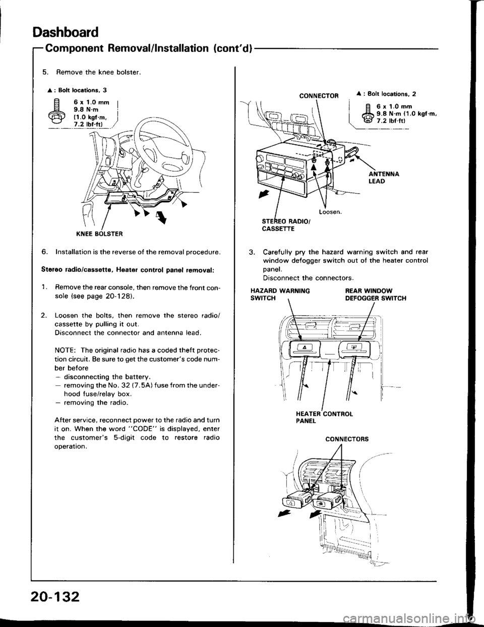
5. Remove the knee bolster.
: Bolt locations, 3
fi 6rt.omm
6 i;i'i#.,7.2 tbr.ftl
?
KNEE
6. Installation is the reverse of the removal Drocedure.
Stol€o radio/cassette, Heater control panal removal:
1 . Remove the rear console, then remove the front con-
sole (see page 20-128).
Loosen the bolts, then remove the stereo radio/
cassette by pulling it out.
Disconnect the connector and antenna lead.
NOTE: The original radio has a coded theft protec-
tion circuit, Be sure to get the customer's code num-
ber belore- disconnecting the battery.
removing the No. 32 17.5A) fuse from the under-
hood fuse/relay box.- removing the radio.
After service, reconnect power to the radio and turn
i1 on. When the word "CODE" is displayed. enter
the customer's 5-digit code to restore radio
operation.
20-132
CONNECTOR
CASSETTE
i Bolt locations. 2
6 x 1.0 mm9.8 N.m {1.0 kgl.m,
3, Carefully pry the hazard warning switch and rear
window defogger switch out of the heater control
Daner.
Disconnect the connectors.
HAZARD WARNINGswtTcHREAR WINOOWDEFOGGER SWITCH
Page 1013 of 1413

Hood
Replacement
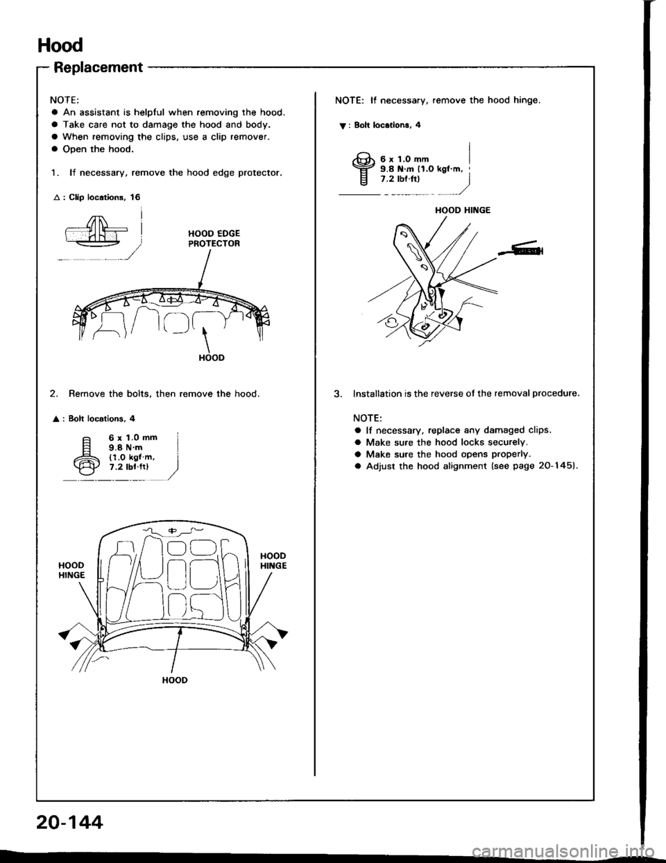
NOTE:
a An assistant is helplul when removing the hood.
a Take care not to damage the hood and body.
a When removing the clips, use a clip remover.
a Open the hood.
1. It necessary, remove the hood edge protector.
: Clip loc.tions, 16
NOTE: It necessary, remove the hood hinge.
V : Boh locationa, 4
I3;;,iH"-,,., I
j .rtor"t
- )
HOOD EDGEPROTECTOR
\HOOD
2. Remove the bolts. then remove the hood.
: Bolt localions, 4
lnstallStion is the reverse of the removal procedure.
NOTE:
a lf necessary, replace any damaged clips.
a Make su.e the hood locks securely.
a Make sure the hood opens properly.
a Adjust the hood alignment (see page 20-1451.
6x1.0mm9.8 N'm{l.O kgl m,7.2 lbl.fr)
HOOD HINGE
n
r)
HOOD
20-144
Page 1022 of 1413

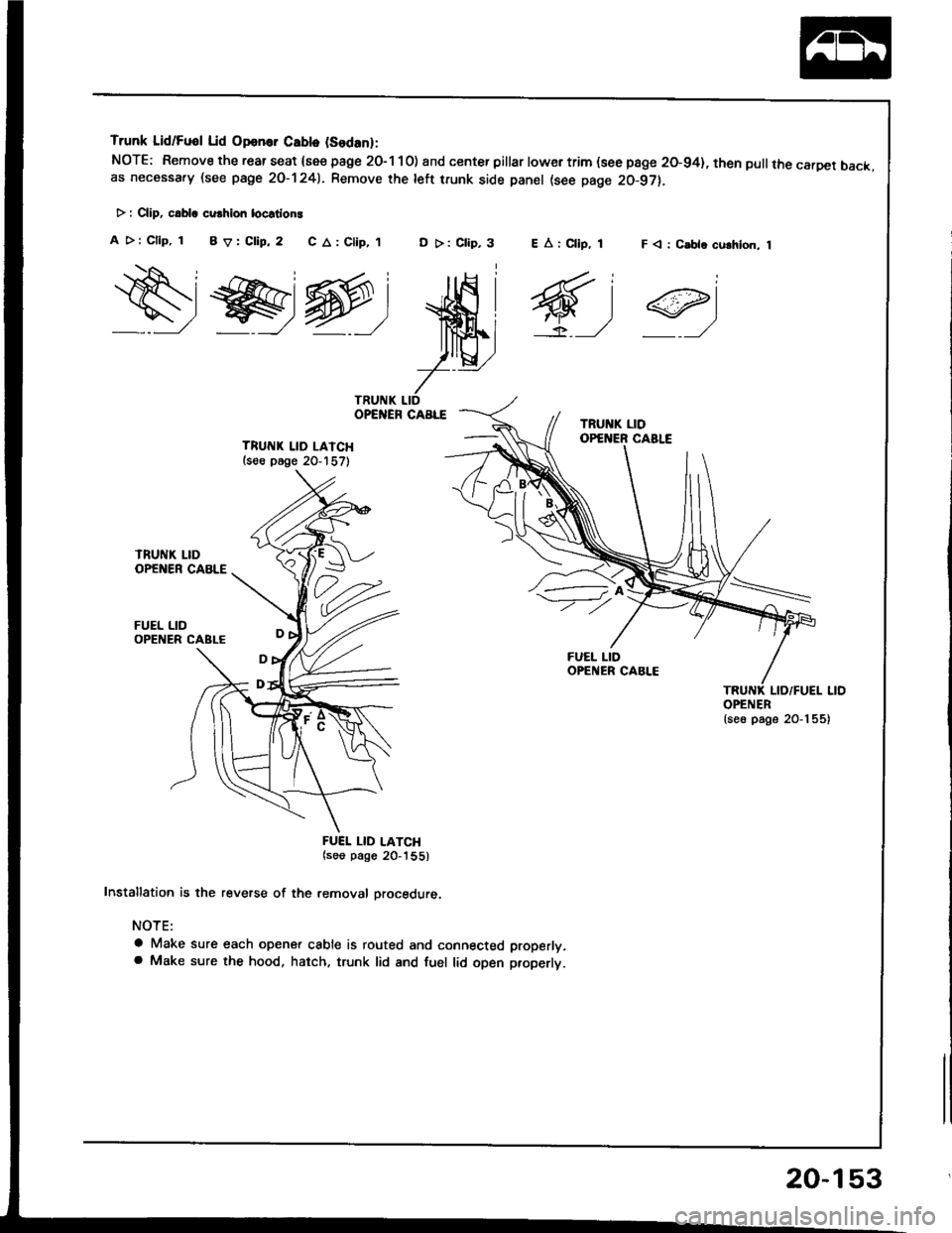
Trunk Lid/Fuol Lid Opan.. Cablo (Sodanl:
NOTE: Remove the rear seat {see page 2O-1 10) and center pillar lowertrim (see page 20-94}, then pullthe carDet back.as necessa.y (see page 2O-1241. Remove rhe left trunk side panel (see page 20-97).
> : CliD, c.bla cu.hion locstlon!
A >: Cllp, 1 BV:Clip,2 C A: Clip,,tD >: Clip,3F < : C.ble culhlon, 1
ws@:
ffi;
7--
TRUITIK LID LAICH(s€e p6ge 20-157)
FUEL LID
FUEI. LID LATCH(soo pago 20_'|55)
Installation is the reverse of the removal orocedure.
NOTE:
a Make sure each opener cable is routed and connected properly.a Make sure the hood, hatch. trunk lid and fuel lid open properlt.
EArCllp, 1
6,1
OPENER{se6 page 20-1 55)
20-153