1994 ACURA INTEGRA Clutch replace
[x] Cancel search: Clutch replacePage 393 of 1413

Automatic Transmission
'l4-2
14-3't 4-6
14-8
14-14
14-23
Hvdraulic Flow ...--...... 14-24
Lock-up System ........ 14-38
Eloctrical Systom
Component Location ............,...,................ I 4-45
Circuit Diagram ............. 14-46'Troubleshooting Procedures ........,..........., l4-48
Symptom-to-Component Chart
Electrical System ...... 14-50
Electrical Troubleshooting
Troubleshooting Flowchart .................... 14-52
Lock-uo Control Solenoid Valve A/8
Test .................. --.... \4-82
ReDlacement ,...,...,..,. 14-82
Shift Control Solenoid Vslve A/B
Test .................. ...... 14-83
Reolacement .............. 14-83
Transmission Control Module (TCM)*ReDlacement ........... 14-84
Mainshalt/CountershaJt SDeed Sensors
Reolacement ............. 14-85
Hydraulic Systom
Symptom-to-Component Chart
Hydraulic System
Road Test
Slall Speed
Test ..................
Fluid Level
Checking/Changing
Pressu.e Testing
Transmission
Transmission
Removal ............. ...... 14-99
lllustrated Index
Right Side Cover .................................. 1 4- 1 04
Transmission Housin9 ..................,,....... I 4-1 06
Torque Converter HousingNalve
Body .................. ... 14- 1O8
Right Side Cover
Removal ............. ...... 14-110
Transmission Housing
Removal ............. .-..-. 14-112
Torque Convener HousingNalve Body
Removal ............. ...... 14-114
Valve Caps
Description ................ 14-116
Valve Body
Repair ................ ...-.. 14-117
Valve
Assembly ...........
Oil Pump
Main Valve Body
Disassembly/lnspection/Reassembly
Regulator Valve Body
Disassembly/lnspection/Reassembly
Lock-up Valve Body
Disassembly/lnspection/Reassembly .......
Secondary Valve Body
Disassembly/lnspection/Reassembly .......
Servo Body
Disassembly/lnspection/Reassembly .......
1st-hold Accumulator/Right Side Covet
Oisassembly/lnspection/Reassembly .,..,..
Mainshaft
Disassembly/lnspection/Reassembly -.. -... 1 4- 1 29
lnsDection ................. 14- 130
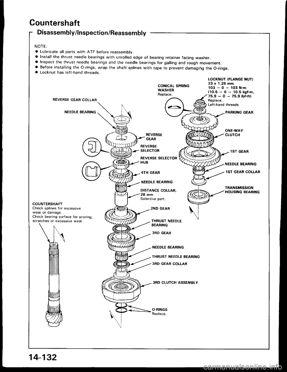
Countershaft
Disassembly/lnspection/Reassembly ....... 14-132
Disassembly/Reassembly ....................... 1 4-1 33
lnsDection ................. 14-134
One-way Clutch/Parking Gear
Disassembly/lnspection .................... -.. -. 1 4-137
Sub-shaft
Disassembly/lnspection/Reassembly ....... 14-138
Disassemblv/Reassemblv ....................... 1 4-1 39
Sub-shaft Bearings
Replacement ............. l4-140
Clutch
fllustrated lndex ................. -..-...-.......... 14-1 41
Disassembly ,,,.,,........ 14-144
Reassembly .............. 14-146
Torque Converter Housing Bearings
Mainshaft Bearing/Oil Seal
Reolacement ......... 14-1 50
Countershaft Bearing Replacement .......,, 14-1 5l
Transmission Housing Bearings
Mainshsft/Countershaft Bearing
Repfacement ...-..-..14-152
Sub-shaft Bearing Replacement .............. 1 4-1 53
Reve.se ldler Gear
lnstallation ................ 14-154
Parking Brake Stopper
lnspection/Adjustment ..........................'14-'154
Transmission
Reassemblv .............,. .14_156
Toroue Converter/Drive Plate ..,..,............... 1 4- 1 63
Transmission
14-120
14-122
14-123
14-124
14-126
14-124
14-86
14-90
't4-92
14-93
14-94
lnstallation
Cooler Flushing'Shitt Cable
Removal/lnstallation ..............................
Adiustment ...-..-......-. 14-'171*Gearshift Selector
Disassembly/Reassembly .....................,. 1 4-17 2*Shift Indicator Panel
Adjustment -..........-...14-173
Throttle Control Cable
fnspection .......,..,...... 14-17 4
Adjustment .............. 14-176
14-164
14-168
14-'t 7 0
Inspection
Page 481 of 1413

NOTES
A.See flushing procedure, page l4-168 and 169.
B.Set idle rpm in gear to specitied idle speed. lf still no good, adiust motor mounts as outlined in engine
section of service manual.
lf the large clutch piston O-ring is broken, inspect the piston groove for rough machining.
lf the clutch pack is seized or is excessively worn, inspect the other clutches Jor wear, and check the
orifice control valves and throttle valves for free movement.
E.It throttle valve B is stuck, inspect the clutches for wear.
lf the 1-2 shift valve is stuck closed, the transmission will not upshift. lI stuck open, the transmission
has no lst gear.
H.lf the 2-3 orifice control valve is stuck, inspect the 2nd and 3rd clutch packs for wear.
ll the orifice cont.ol valve is stuck, inspect the 3rd and 4th clutch packs for wear.
lf the clutch Dressure control valve is stuck closed, the transmission will not shilt out of 1st gear.
K.improper alignment or main valve body and torque converter housing may cause oil pump seizure. The
symptoms ale mostly an rpm-related ticking noise or a high-pitched squeak.
L.ll the ATF strainer is ctogged with panicles of steel or aluminum, inspect the oil pump and ditferential
pinion shaft. lt both are OK and no cause lor the contamination is found, replace the torque converter.
M.lf the 1st clutch feedpipe guide in the right side cover is scored by the mainshaft, inspect the ball bear-
ing for excessive movement in the transmission housing. lf OK. replace the right side cover as it is dent-
ed. The O-ring under the guide is probably worn.
N.ReDlace the mainshstt if the bushing for the 4th feedpipe is loose or damaged.
It the 4th feedpipe is damaged or out ot tound, replace the right side cover'
Replace the subjshaft it thtbushing for the 1st-hold Jeedpipe is loose or damaged.
lf the 1st-hold feedpipe is damaged or out of round, replace it.
Replace the mainshaft if the bushing lor the 1st feedpipe is loose or damaged.
lf the lst feedpipe is damaged or out ot round, replace it.
o.A *o- r, da."s"d "p-g clutch is mostly a result of shifting the transmission in El or Lq! position
while the wheels rotate in reverse, such as rocking the car in snow.
P.InsDect the frame for collision damage.
o.Inspect for damage or wear:
1. Reverse selector gear teeth chamfers.
2. Engagement teeth chamters of countershaft 4th and reverse gear.
3. Shift fork for scutt marks in center.
4. Differential Dinion shaJt for wear under pinion gears.
5. Bottom of 3rd clutch for switl marks.
Replace items 1 , 2, 3 and 4 it worn or damaged. lf transmission makes clicking, grinding or.whirring
noise, atso replace mainshaft 4th gear and reverse idler gear and countershaft 4th gear in addition to
1,2,3ot4.lf ditiersntial Dinion shaft is worn, overhaul differential assembly, and replace ATF strainel, and thoroughly
clean transmission, tlush torque convertet, cooler and lines.
lf bottom of 3rd clutch is swirled and transmission makes gear noise, replace the countershaft and tinal
driven gear.
R.Be wry careful not to dsmage the torque converter housing when replacing the main ballbearing. You
may al;o damage the oil pump when you torque down the main valve body. This will result in oil pump
seizure it not detected. Use proper tools.
qInstall the main seal tlush with the torque converter housing, lf you push it into the torque converter
housing until it bottoms out. it will block the oil return passage and result in damage.
T,Harsh do\/vnshiJt"\./l,'hen coasting to a stop with zero th.ottle may be caused by a bent-in throttle valve
retainer/cam stopper. Throttle cable adjustment may clear this problem.
ifuitle cable adjustment is essential for proper operation of the transmission. Not only does it affect
the shift points if misad,usted, but also the shift quality and lock-up clutch operation'
A cable adjusted too long will result in throttle pressure being too low for the amount of engine torque
input into ihe trsnsmission and may cause clutch slippage. A cable adjusted too short will result in too
hi;h throttle pressure which may cause harsh shitts, erratic shrfts and torque con
14-89
Page 496 of 1413

O RtcHT slDE covER pRoTEcToR
@ RrcHT stDE covER
O MAtt{sHAFr spEED sENsoR
@ o-RtNG Reptace.
@ cour{TERSHAFT SPEEO SENSOR
@ HARNESS STAY
O RoLLCR
@ COLLAR
O O-RING Reptace.
@ FEED PIPE FLAI{GE
@ o-RrNG
@ sIrlAP RING
@ 3RD CIUTCH FEED PIPE
@ COUNTERSHAFT LOCKNUT (FLAt{cE f{UTl Reptace.
@ coultTERsHAFf col{tCAL SpRtt{c WASHER Reotace.
@ PARKI G GEAR
@ oNE-waY cLUTcH
@ couNTERsHAFr lsr GEAR
@ NEEDLE BEARING
@ couNTERsHAFr tsr GEAR coLLAB
@ O-RING Reptace.
@ l sT-HoLD accuMuLAToR ptsToN
@ isT-HoLD ACCUMULAToR spBfi{c
@ o-RtNG Reptace.
@ rsT-HoLD ACGUMULAToR covER
@ SNAP Rrr{G
@ PAFKING BRAKE PAWL
@ PARKING BRAKE PAWL SPRII{G
@ PARKING BRAKE PAWL SHAFT
@ PARKING aRAKE PAWL SToPPER
@ LOCK wasHEn Reptace.
@ PARKI G BRAKE s?oPPER
@ PARKING BRAI(E LEVER
@ PARKI G BRAKE LEVER SPBING
@ DowEL PrN
@ O-RltIG Reptace.
@ RTGHT stoE covER GASKET Feptace.
@ isT ct-uTcH FEED ptpE
@ o-RtNG Reptace.
TOROUE SPECIFICATIONS
@ FEED PIPE GUIDE
@ SNAP RING
@ MAINSHAFT LocKNUT {FLANGE NUT) ReDIace.
@ MAfISHAFT CONTCAL SpRtNG WASHER Reotsce.
@ IsT cLUTcH ASSEMBLY
@ O-RING Reptace.
@ THRUST WASHER
@ THRUSI NEEDLE BEARI G
@ EEDLE BEARING
@ MAI'{SHAFT lsT GEAR
@ THRUST WASHER
@ MAINSHAFT lsT GEAR coLLAR
@ RoLLER
@ coLLAR
@ O-Rlt{c Reptace.
@ FEEo PIPE FLANGE
@ o-RING R€ptace.
@ SNAP RING
@ lsr-HoLD cLUTcH FEED ptpE
@ SUB-SHAFT LoCKNUT IFLAt{c€ NUTI Reptace.
@ suB-sHAFr cot{tcAl spRtNG WASHER Reptace.
@ SU8-SHAFT lST GEAR
@ LOCK WASHER f,eptace.
@ THRoTILE cor{TRoL LEVER
@ THRoTTLE coNTRoL I.EVER SPRING
@ oll sEAt Reptace.
@ THRoTTI"E coNTRoL CABLE STAY
@ sHtFT CONTROL SOLEI{O|O HARNESS
@ Jor T BoLT
@ ATF COOLER PIPE
@ SEAL|NG WASHERS Roptace.
@ ATF cooLER P|PE
@ ATF LEVEL GAUGE
@ JOINT EOLT
@ vEHtcLE spEED sEf{soR
@ o-RtNG Reptace.
@ DRAIN PLUG
@ SEALING WASHER Replace.
Ret No.Torque ValueBolt SizeRemarks
B
D
F
K
L
'12 N.m (1 .2 kgf .m, 8.7 lbJ.tt)
14 N.m (1.4 kgf.m, 10lbf.ft)
22 N.m 12.2 kgf.m, 16 lbf.ft)
8 N.m (O.8 kgf.m, 6 lbf.ftl
28 N'm (2.9 kgf .m, 21 lbf.ttl
49 N.m (5.O kgf.m, 36 lbf'ft)
93 N.m {9.5 kgf.m, 69 lbt.ft}
103 N.m {1O.5 kgf.m, 75.9 lbf.ftl-O-
1O3 N.m (10.5 kgf'm. 75.9 lbf.ft)
93 N.m (9.5 kg-m, 69 lb-ft)
6 x 1,O mm
6 x 1.O mm
I x 1.25 mm
5x0.8mm
12 x 1-25 mm
18 x '1.5 mm
tY x t.z5 mm
23 x 1.25 mm
'19 x 1.25 mm
Specialbolt
ATF cooler pipe joint bolt
Drain plug
Mainshaft locknut(flange nut):
Left-hand threads
Countershaft locknut(tlange nut)
Lett-hand threads
Sub-shatt locknut(flange nut)
14-105
Page 498 of 1413
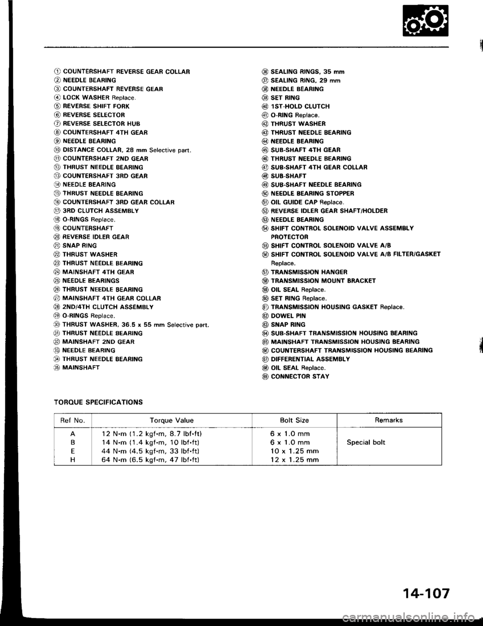
O) COUNTERSHAFT REVERSE GEAR COLLAR
@ NEEDLE BEARING
G) COUNTERSHAFT REVERSE GEAR
@ LOcK WASHER Reptace.
@ REVERSE sHIFT FoRK
@ BEVERSE SELECToR
O REVERSE SELECToR HUB
@ couNTERSHAFT 4TH GEAR
@ NEEDLE BEARING
@ DTSTANCE COLLAR, 29 mm Setecrive part.
@ coUNTERSHAFT 2ND GEAR
@ THRUST NEEDLE BEARING
@ GoUNTERSHAFT 3RD GEAR
@ NEEDLE BEARING
@ THRUST NEEDLE EEARING
G) COUNTERSHAFT 3RD GEAR COLI-AR
O 3RD cLuTcH ASSEMBLY
(!) O-RINGS Replace.
@ coUNTERSHAFT
@ REVERSE IDLER GEAR
@ SNAP RING
@ THRUST WASHER
@ THRUST NEEDLE BEARING
@ MAINSHAFT 4TH GEAR
@) NEEDLE BEARINGS
@ THRUST NEEDLE BEARING
@ MAINSHAFT 4TH GEAR coLLAR
@ 2ND/4TH cLUTcH ASSEMBLY
et O-RINGS Replace.
@ THRUST waSHER, 36.5 x 55 mm Setective pan.
@ THRUST NEEDLE EEARING
@ MA|NSHAFT 2ND GEAR
€, NEEDI.E BEARING
@ THRUST NEEDLE EEARING
.O MAINSHAFT
@ SEAL|NG RtNGs, 3s mm
@ SEAL|NG R|NG, 29 mm
@ NEEDLE BEARING
@ sET RING
@ 1ST-HOLD CLUTCH
@ O-RING Replace.
@ THRUST WASHER
@ THRUST NEEDLE BEARING
@ NEEDLE BEARING
@ SUB.SHAFT 4TH GEAR
@ THRUST NEEDLE BEARING
@ SUB.SHAFT 4TH GEAR COLLAR
@ SUB-SHAFT
@ SUB.SHAFT NEEDLE BEARING
@ NEEDLE BEARING SToPPER
@ otL GUTDE cAP Reptace.
@ REVERSE IDLER G€AR SIIAFT/HOLDER
@ NEEDLE BEARII{G
@ sHIFT GONTROL SOLENOID vAI.vE ASSEMBLY
PROTECTOR
@ sHrFT CONTROL SOLENOTD VALVE A/B
@ SHIFT CONTROL SOLENOID VALVE A/B FILTER/GASKET
Replace.
@ TRANSMISSION HANG€R
@ TRANSMtsstoN MouI{T BRAGKET
@ oll SEAL Replace.
@ sET RING Replace.
@ TRANSMISSION HOUSING GASKET Replace.
@ DOWEL PrN
@ SNAP RI G
@ SUB-SHAFT IRANSMtSStON HOUSNG AEARTNG
@ MAINSHAFT TRANSMISSION HOUSING BEARING
@ coUNTERSHAFT TRANSMISSION HOUSING BEARING
@ DIFFERENTIAL ASSEMELY
@ OtL SEAL Replace.
@ CoNNECTOR STAY
TOROUE SPECIFICATIONS
Rel No.Torque ValueBolt SizeRemarks
B
E
H
12 N.m (1.2 kgf.m,8.7 lbt.tt)
14 N.m (1 .4 kgf .m. 10 lbf .ft)
44 N.m (4.5 kgt.m, 33 lbf .ft)
64 N.m (6.5 kgf .m, 47 lbf .ft)
6 x 1.O mm
6 x 1.O mm'lO x 1.25 mm
12 x 1.25 mm
Special bolt
14-107
Page 501 of 1413
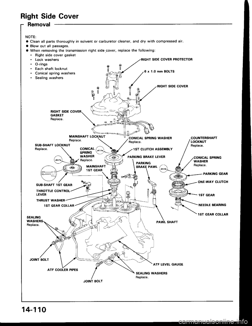
Right Side Cover
Removal
NOTE:
a Clean all pans thoroughly in solvent or carburetor cleaner, and dry with compressed air,
a Blow out all passages.
a When removing the transmission right side cover, replace the following:. Right side cover gasket. Lock washers. O-rings. Each shaft locknut. Conical spring washers. Sealing washers
RIGHT SIDE COVER
SIDE COVER PROTECTOR
1.O mm BOLTS
SUB.SHAFTReplace.
THROTTLE CONTBOLLEVER
MAINSHAFT1ST GEAR
CONICALSPRINGWASHERReplace.WASHERReplace.
PARKING GEAR
ONE.WAY CLUTCHSUB.SHAFT 1ST GEAN
JOINT AOLT
THRUST WASHER,I ST GEAB COLLAR
1ST GEAR
NEEDLE BEABING
lST GEAR COLLAR
ATF LEVEL GAUGE
SEALING WASHERSReplace.
14-110
ATF COOLER PIPES
Page 502 of 1413
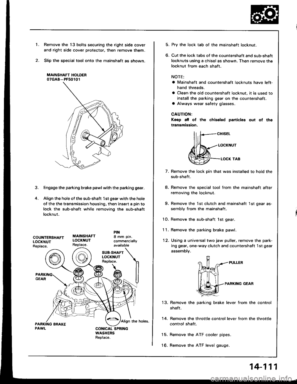
Remove the 13 bolts securing the right side cover
and right side cover protector, then remove them.
Slip the special tool onto the mainshaft as shown.
MAINSHAFT HOLOER07GAB-PF50101
3. Engage the parking brake pawl with the parking gear.
4. Align the hole ot the sub-shaft l st gear with the hole
of the the transmission housing, then insert a pin to
lock the sub-shaft while removing the sub-shaft
locknut.
'1.
COUNTERSHAFTLOCKNUTReplace.
MAINSHAFTLOCKNUTReplace.
8 mm pin.
comm€rciallyavailable
SU8-SHAFTLOCKNUTReplace.
Align the holes.
CONICAL SPNINGWASHERSReplace.
5. Pry the lock tab of the mainshaft locknut.
6. Cut the lock tabs of the countershaft and sub-shaft
locknuts using a chisel as shown. Then remove the
locknut from each shatt.
NOTE;
a Mainshaft and countershaft locknuts have lett-
hand threads.
a Clean the old countershaft locknut, it is used to
install the parking gear on the countershaft.a Always wear safety glasses.
CAUTION:
Keop all of th€ chis€led panicles out of the
tlanamigsion.
llrF-"""*
,fl(,-..- LocKNUr
@-.**'o'
7.
8.
q
10.
11.
12.
13.
14.
15.
to.
Remove the lock pin that was installed to hold the
sub-shaft.
Remove the special tool from the mainshaft after
removing the locknut.
Remove the 1st clutch and mainshaft 1st gear as-
sembly from the mainshaft.
Remove the sub-shaft 1st gear,
Remove the parking brake pawl.
Using a universal two jaw puller. remove the park-
ing gea.. one-way clutch and counlershatt 1st gear
assembly.
PARKING GEAR
Remove the parking brake lever from the control
shaft.
Remove the throttle control lever from the throttle
control shaft.
Remove the ATF cooler pipes.
Remove the ATF level gauge.
14-111
Page 520 of 1413
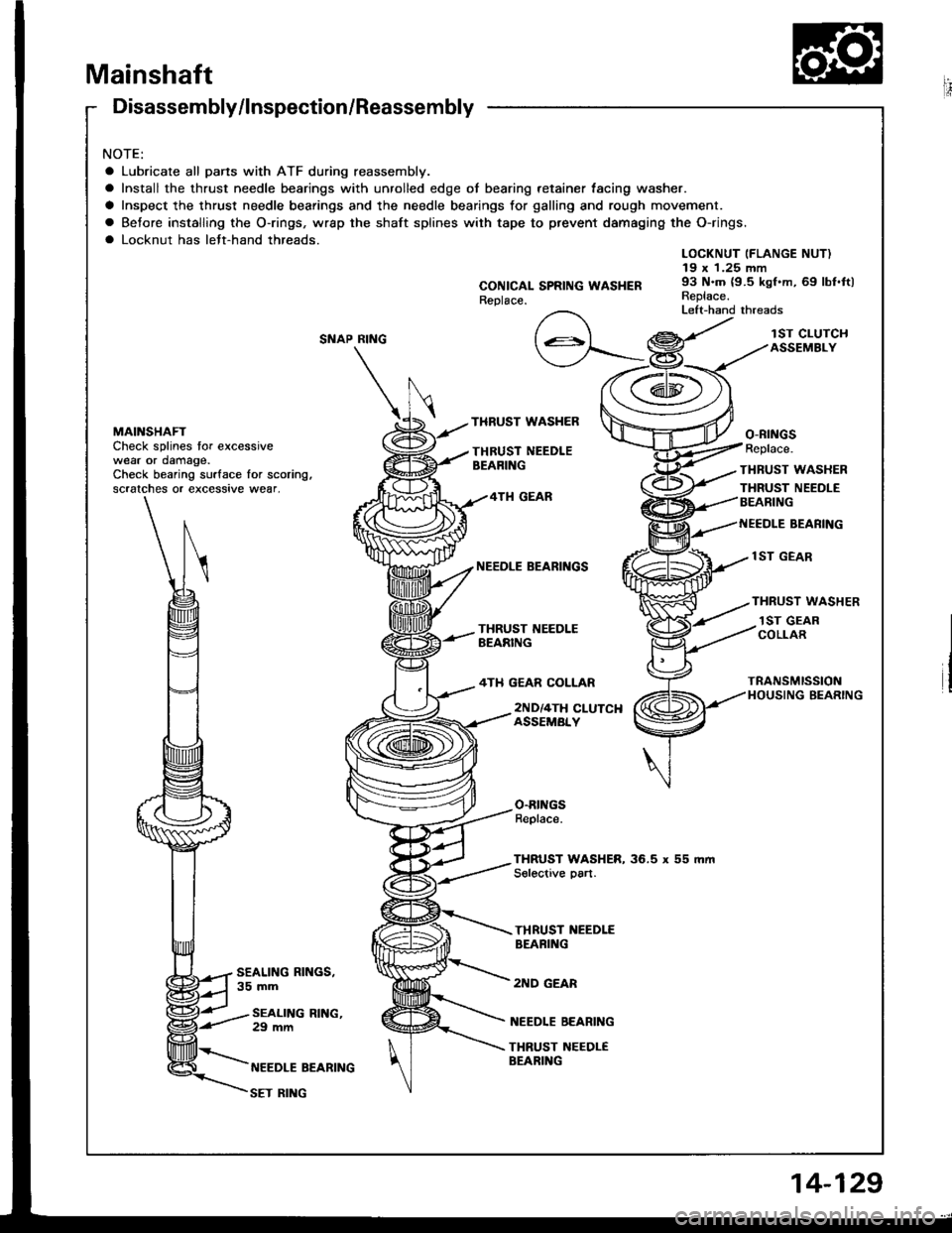
Mainshaft
Disassembly/lnspection/Reassembly
NOTE:
a Lubricate all pans with ATF during reassembly.
a Install the thrust needle bearings with unrolled edge of bearing retainer lacing washer.
a Inspect the thrust needle bearings and the needle bearings for galling and rough movement.
a Betore installing the O-rings, wrap the shaft splines with tape to prevent damaging the O-rings.
a Locknut has lett-hand threads.
RING
\
MAINSHAFTCheck splines tor excessivewear or damage.Check bearing surface for scoring,scralches or excessive wear,
CONICAL SPRING WASI{ERReplace.
LOCKNUT (FLANGE NUT)19 x 1.25 mm93 N.m {9.5 kgf.m, 69 lbf.ftlReplace.Left-hand threads
SNAP
THRUST WASHER
THRUST NEEDLEBEARING
lST CLUTCHASSEMBLY
o-ntNGsReplace.
THRUST WASHER
THRUST NEEDLEBEARING4TH GEAR
NEEOLE BEARIT{GS
4TH GEAR COLLAR
lST GEAR
THRUST WASHER
BEANING
1ST GEARCOLLAR
TRANSMISSIONHOUSING BEARING
SEALING RINGS,35 mm
2ND/4TH CLUTCHASSEMBLY
NEEDLE BEARING
THRUST NEEDLEBEARING
O.RINGSReplace.
THRUST WASHER, 36.5 x 55 mmSolective part.
THRUST NEEDLEBEAFING
2ND GEAR
SEALING RING.29 mm
NEEDLE BEARING
SET RII{G
Page 523 of 1413
Countershaft
Disassembly/lnspection/Reassembly
NOTE:
a Lubricate all parts with ATF belore reassembly.a Install the thrust needle bearings with unrolled edge of bearing retainer facing washer.a Inspect the thrust needle bearings and the needle bearings tor galling and rough movement.a Before installing the O rings, wrap the shaft splines with tape to prevent damaging the O-rings.a Locknut has left-hand threads.
CONICAL SPRINGWASHERReplace.
LOCKNUT {FLANGE NUTI23 x 1.25 mm1O3-0-lO3N.m{10.5-O-'l0.5ksf.m,75.9*O-75.9tbf.fr)Replace.Left-hand threads
REVERSE GEAR COLLAR
NEEDLE EEARINGPARKING GEAR
ONE.WAYCLUTCHREVERSEGEAR
BEVERSESELECTOR
REVERSE SELECTORHUB
4TH GEAR
NEEDLE BEARING
DISTANCE COLLAR,28 mmSelective part.
.I ST GEAR
NEEDLE EEARING
lST GEAR COLLAR
TRANSMISSIONHOUSING BEARING
COUNTERSHAFTCheck splines for excessivewear or damage.Check bearing surface for scoring,scratches or excessive wear_
2ND GEAE
THRUST NEEDLEBEARING
3RD GEAR
NEEDLE BEARING
THRUST NEEDLE BEARING
3RD GEAR COLLAR
3RD CLUTCH ASSEMBLY
O-RINGSReplace.