Page 1348 of 1413
Cruise Control
MAIN SWITCHTest, page 23-250Replacement, page 23-250
Component Location Index
a All SRS 6l6ctrical wiring harnessos aro covorod with
yallow insulation,
a Bofo.6 disconnecting any part of th6 SRS wire har-
ness, connoct th€ shon conneclor(s).
a Replaco the ontiro affected SRS halness assombly if
it has an op€n circuit or damagod widng.
SRS MAIN HARNESS(Cov.rod wilh yollow In.ulation)
CRUISE LIGHT(Built into gauge assembly)Bulb Locations, page 23-115
SET/RESUME SWITCHTest. page 23-248Repfacemont, page 23-248
BRAKE SWITCHTest. page 23-251
CLUTCH SWITCH (M/TI
Test, page 23-251
CRUISE CONTROLfnput Test, page 23-246A/T GEAR POSITIOI{swtTcHTest, page 23-136, 252
23-242
Page 1357 of 1413
Brake Switch Test
'1. Disconnect the 4-P connector from the switch.
2. Check for continuitv between the terminals accord-
ing to the table.
3. It necessary, replace the switch or adjust pedal
height {see section 19).
Glutch Switch Test (M/T)
I� Disconnect the 2-P connector from the switch,
2. Check {or continuitv between the terminals accord-
ing to the table.
3. lf necessary, replace the switch or adjust pedal
height (see section 12).
I
Terminal
il"*on---\B
BELEASEDo---o
PUSHED-o
| ormtnal
Clutch podal \
RELEASEDoo
PUSHED
23-251
Page 1359 of 1413

1.
2.
3.
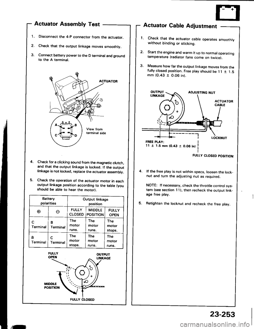
Actuator Assembly Test
Disconnect the 4-P connector from the actuator.
Check that the output linkage moves smoothly.
Connect battery power to the D terminal and groundto the A terminal,
ACTUATOR
Check for I clicking sound trom the magnetic clutch,and that the output linkage is locked. lf the outDutlinkage is not locked, replace the actuator asssmblv.
Check the operation oJ the actuator motor in eachoutput linkago position according to the table (youshould be able to hear the motor).
Actuator Cable Adjustment
Check that the actuator cable operares smoothtvwithout binding or sticking.
Start the engine and warm it up to normaloperatingtemperature (radiator fans come on twicel,
Measure how far the output linkage moves from thefully closed position. Free play should be 1 1 1 1.5mm (O.43 I 0.06 in).
4.
FREE PLAY:1 1 I 1.5 mm (0.43 r 0.06 int
FULLY CLOSED POSITION
4. lf the free play is not within specs, loosen the lock-nut and turn the adjusting nut as required.
NOTE: lf necessary, check the throttle controlsys-tem {see section 1 I }, then recheck the output link-age free play.
5. Retighten the locknut and recheck the free play.
Battery
polaritiesOutput linkage
position
oFULLY
CLOSED
MIDDLE
POStTtON
FULLY
OPEN
Terminal
B
Terminal
The
molor
runs.
The
molor
runs.
The
molor
srops.
I
TerminalTerminal
The
motor
stops.
The
motor
runs.
The
motor
runs.
FULLY CLOSED
,tilr
23-253