Page 581 of 1413

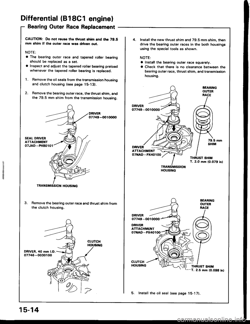
Differential (B18c1 eng:nel
Bearing Outer Race Replacement
CAUTION: Do not rous€ the thrust lhim and tho 79.8mm shim il tho outer rac6 was ddvon out.
NOTE;
a The bearing outer race and taper€d toller bearingshould be reDlaced as a set.a Inspect and adjust the tapered roller bearing proload
whenever th€ tapered roll€f bearing is roplac€d.
1 . Remove the oil seals from the transmission housing
and clutch housing (see page 15-13).
2. Remove the bearing outer raca, the thrust shim, andthe 79.5 mm shim from th€ transmission housing.
Remove the bearing outer racs and thrust shim tromthe clutch housing.
TRANSMtSStOl{ HOUStl{c
15-14
5. lnstall the oil sesl (see page 15-171.
4.Install the new thrust shim and 79.5 mm shim, then
drive the bearing outer races in the both housings
using the special tools as shown.
NOTE:
a Install the bearing outsr race squarely.a Check that there is no clearance between tha
bearing outer race, thrust shim, and transmission
housing.
BEARIl{GOUTER
07749-OOTOOOO
ONNERATTACHMENTOTttAD-PX/IOlOO
Page 582 of 1413

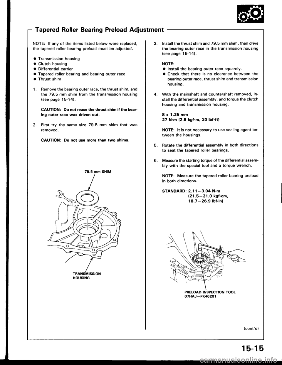
Tapered Roller Bearing Preload Adjustment
NOTE: lf any of the items listed below were replaced,
the tapered roller bearing preload must be adjusted,
a Transmission housing
a Clutch housing
a Diffe.ential carrier
a Tapered roller bearing and bea,ing outer race
a Thrust shim
1 . Remove the bearing outer race, the thrust shim, and
the 79.5 mm shim from the transmission housing
(see page 1 5- 14).
CAUTION: Do not reuss lhe thrust shim it the bear-
ing outer raco was driven out.
2. First t.y the same size 79.5 mm shim that was
removeo.
CAUTION; Do not uso moro than two shims.
79.5 rnm SHIM
HOUSING
4.
o.
Instsllthe thrust shim and 79.5 mm shim, then drive
the bearing outer race in the transmission housing
{see page l5-14).
NOTE:
a Install the bearing outer race squarely.
a Check that there is no clearance between the
bearing outer race. thrust shim and transmission
housing.
With the mainshaft and countershaft.emoved, in-
stsllthe differential assembly, and lorque the clutch
housing and transmission housing,
8 x 1.25 mm
27 N.m 12.8 kgf.m, 20 lbf.ft)
NOTE: lt is not necessary to use sealing agent be-
tween the housings.
Rotate the ditterential assembly in both directions
to seat the tapered roller bearings.
Measure the starting torque of the differenlial assem-
bly with the special tool and a torque wrench.
NOTE: Measure the tapered roller bearing preload
in both directions.
STANDARD: 2.1 1 -3.O4 N.m(21.5-31.0 kgf'cm,
18.7-26.9 lbf.inl
{cont'd}
15-15
Page 584 of 1413
1.lnstallthe oil seal into the transmission housinq us-
ing the special tools as shown.
Install the new oil seal into the clutch housing using
the soecial tools as shown.
DRIVER07749-OOIOOOODRIVER07749-OOl OO00
OIL SEALReplace.OIL SEALReplace.
HOUStl{G
Oil Seal lnstallation
15-17
Page 952 of 1413

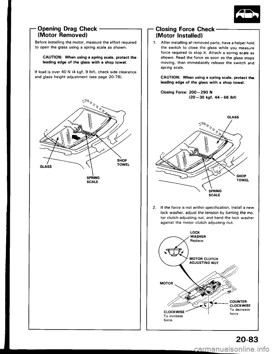
Opening Drag Check
(Motor Removedl
Betore installing the motor, measure the etfort required
to open the glass using a spring scale as shown.
CAUTION: When using a spring scale, protoct the
leading edg6 ot th€ glass with a shop towel.
lf load is over 40 N (4 kgt, 9lbf). check side clearance
and glass height adjustment (see page 2O-78).
Closing Force Check
(Motor Installedl
1. After installing all removed parts, have a hetper hotd
the switch to close the glass while you measure
torce required to stop it. Attach a spring scale asshown. Read the force as soon as the glass siops
moving, then immediately release the switch andspnng scare.
CAUTION: When using a spring scale, protoct tho
leading odge ol th€ glass with a shop towel.
200-290 N(20 - 30 kgf, rt4- 66 lbf)
lf the force is not within specification, install a new
lock washer, adjust the tension by turning the mo-
tor clutch adjusting nut, and bend the lock washer
against the motor clutch adjusting nut.
LOCKWASHERReplace.
'r coul{TER-cLocKwrsETo decrease
GLASS
\
20-83
Page 1087 of 1413
A/C Thermostat
Test
Connect battery power to terminal C and ground termi-
nal B, and connect a test light between terminals A and
NOTE: Use a 12 V, 3W- 18Wtest light.
Dip the A-/C thermostat into a cup filled with ice water,
and check the test light.
The light should go off at 37"F (3"C) or less. and should
come on at 39"F (4"C1 or more.
lf the light doesn't come on and go off as specified,
replace the Ay'C thermostat.
There should be continuity between the A and C term!nals when power and ground are connected to the Band D terminals.
There should be no continuity when power is discon-nected.
. Radiator fan relay
Condenser fan relay
Compressor clutch relay
Relays
a
a
,I Ir-b
InP.I I
12V.3W-18W
ABC
22-19
Page 1091 of 1413

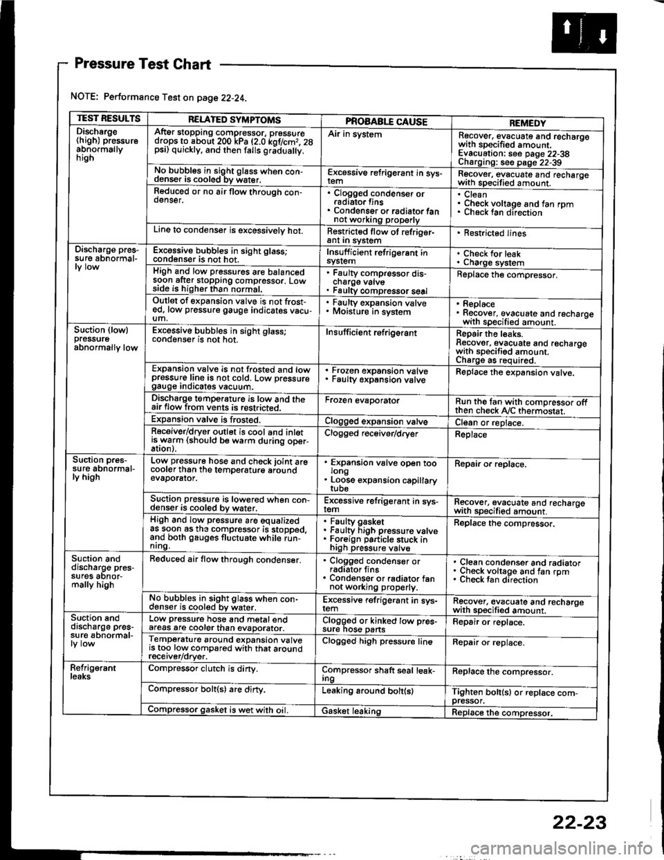
Pressure Test Chart
NOTE: Performance Test on page 22-24.
TEST RESULTSRELATED SYMPTOMSPROAABLE CAUSEREMEDYDischsrge(high) pressureabnormallynrgn
AftEr stopping compressor, pressuredrops to about 200 kPa (2.0 kof/cmr. 28psi) quickly, and then falls gr;dua y.
Air in systemRecover, evacuate and recharqowith sDecified amount. -
Evacuation: see Daqe 22-38Charoino: se6 D;op--2?-?qNo bubbles in sight g16ss when con-denser is cooled bv water.E-\cessive refrigerant in sys-Recover, evacuate and recharqewith specitied amount. -
Reduced or no air flow through con-oenser.Clogged condenser orradiato. finsCondenser o. radiator fannot working properly
CleanCheck voltage and fan rpmunecK lan ofeclton
Line to condenser is excessivelv hot.Restricted flow of refriger-ant In syslem. Restricted lines
Discharge pres-su re abnormal-Excossive bubbles in sight glass;condenser is not hot.Insuff icient refrigerant insyslemCheck for leakCharge systemHigh and low pressures are balancedsoon after stopping compressor. Lowside is higher than normal,
Faulty compressor dis-cnarge vaNsFaulty compressor seal
Replace the compressor.
Outlet of expansion vslve is not frost-ed, low pressure gauge indicates vacu-um,
. Faulty expansion valve. Moisture in sysiem. Replace. Recover, evacuate and recharoewith specified amount. -
Suction (lowlpressureabnormally low
Excessive bubbles in sight glass;conqenser rs not hot_Insuff icient ref rigerantReoair the leaks.Reaover, evacuate and recharoewith sDecifisd amount. -
Charqe as required.Expansion valve is not trosted and lowpressur€ line is not cold. Low pressuregauge Inorcates vacuum.
Frozen expansion valveFaulty expansion valveReplace the expansion valve.
Discharge temperaturg is low and theair flow from vents is restricted.Froren evaporatorRun the tan with comoressor oftthen check Ay'C thermostat.Expansion valve is frost€d.Clogged expansion valveCl€an or replace.Receiver/dryer outlet is cool and inletisrryarm (should be warm during oper-Clogged r€ceiver/dry€rReplace
Suction pres-su re abnormal-ly high
Low pressure hose and check joint arecooler than the temDeraturo aroundevaDorator.
'
ffin"nsion u"lu" oD"n too
. Loose expansion capillary
Repair or replace.
Suction pressure is lowered when con-denser is cooled by water,Excessive refrigerant in sys-remRecover, evacuate and recharqewith sDecifi€d amount. -
High and low pressure are equalizedas soon as the compressor is stopped,and both gauges fluctuate while run-nrng.
Faultv oasketFaulty Figh pressure valveForeign particle stuck inhigh pressure valve
Replace the compressor.
Suction anddischarg€ pres-sufes aonor-mally high
Reduced air flow through condenser.. Clogged condenser orradiator fins. Condenser or radiator fannot working properly.
Clean condenser and radiatorCheck voltage and fan rpmCheck fan direcrion
No bubbles in sight glass when con-cl€nser is cooled bv water.Excessive refrigerant in sys-remRgcover, €vacuate and recharoewith sp€cified amount.Suction snddischarge pres-su r€ abnormal-
Low pressure hose and metal endafeas are cooler than evaDorator.Clogged or kinked tow pre€-sure nos€ pansFepair or replace.
Temperature around expansion valveis too low compared with that aroundrecerver/orver.
Clogged high pressure lineRepair or replace.
Refrig€rantleaksCompressor clutch is dirty.Compressor shaft seal leak-IngReplace the comDressor.
Compressor bolt(s) are dirty.Leaking around bolt(s)Tighten bolt(sl or replace com-pressor.Compressor gasket is wet with oil. IGasket leakingReplace the compressor.
22-23
Page 1097 of 1413
lllustrated lndex
CENTER BOLT
CLUTCHSETInspoc!on,page 22-32
SNAP RING AReplace.
-t COMPRESSOR COMPLETE
f-- lDo nor disassemble)
colLInspection, pag6 22 32
RELIEF VALVE
'-f
Replacement, page 22-34
22-29
Page 1098 of 1413
Compressor
Glutch Inspection
Check the plated parts ot the pressure plate tor color
changes. peeling or other damage. lf there is dam-
8ge, replace the clutch set.
Check the pulley bearing play and drag by rotating
the pulley by hand. Replace the clutch set with a new
one if it is noisv or has excessive play/drag
Measure the clearance betlveen the pulley and the
pressure plate all the way around. lf the clearance is
not within specified limits, the pressure plate must be
removed and shims added or removed as required.
Jollowing the procedure on page 22-33.
Clearrnce: 0.50 t 0.15 mm {0.02 i 0.01 inl
NOTE: The shims are available in three thicknesses:
0.1 mm, 0.3 mm and 0.5 mm.
22-32
Check resistance of the tield coil.
Fisld Coil Rosistance: 3.6 t 0.2 ohm at 68"F {20'C)
lf resistance is not within specifications, replace the
field coil.