Page 343 of 1413

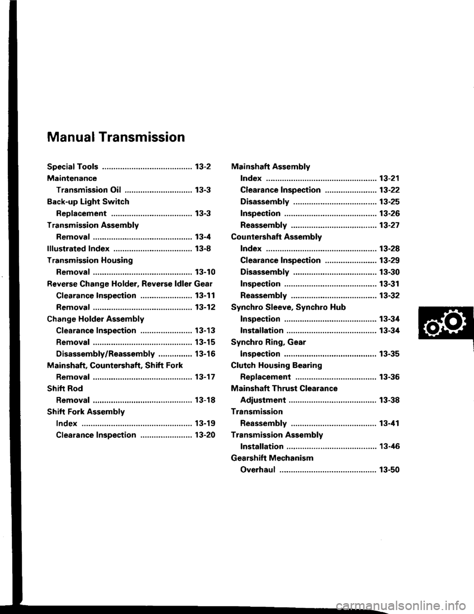
Manual Transmission
Special Toofs ............. 13-2
Maintenance
Transmission Oi1,...,........,........,.,..... 13-3
Back-up Light Switch
Replacement ......... 13-3
Transmission Assembly
Removal ..,.......,...... 13-4
lllustrated Index ................................... 13-8
Transmission Housing
Removal ...........,..... 13-10
Reverse Change Holder, Reverse ldler Gear
Glearance lnspestion ....................... 13-1 1
Removaf ................. 13-12
Change Holder Assembly
Clearance Inspection ....................... 1 3-1 3
Removal ................. 13-15
Disassembly/Reassembly ............... 13-16
Mainshaft, Gountershaft, Shift Fork
Removal ...,............. 13-17
Shift Rod
Removal ................. 13-18
Shift Fork Assembly
Index ................ ...... 13-19
Clearance Inspection ....................... 13-20
Mainshaft Assembly
Index ................ ...... 13-21
Clearance f nspection ....................... 13-22
Disassembly .......... 13-25
Inspection .............. 13-26
Reassembly ........... 13-21
Countershaft Assembly
Index ................ ...... 13-28
Clearance Inspection ....................... 13-29
Disassembly .......... 13-30
Inspection .............. 13-31
Reassembly ........... 13-32
Synchro Sleeve, Synchro Hub
Inspection .............. 13-34
Installation ............. 13-34
Synchro Ring, Gear
lnspection .............. 13-35
Clutch Housing Bearing
Replacement ......... 13-36
Mainshaft Thrust Clearance
Adiustment ............ 13-38
Transmission
Reassembly ........... 13-tl1
Transmission Assembly
lnstallation ............. 13-46
Gearshift Mechanism
Overhaul ................ 13-50
Page 347 of 1413
Removo tho clutch pip€ bracket and th€ slave cylin-
oer.
NOTE: Do not operate the clutch pedal once th€
slavg cvlinder has been r€moved.
R€move the three uppor transmission mounting
bolts 8nd lower staner motor mounting bolt.
STARTEBMOTOBMOUNNNGBOLT
MOUNNNGBOLTS
10. Remove the engine splash shield.
11. Disconnect the heated oxygen sensor (HO2S) con-
nector, lhsn rsmove the exhaust pipe A, and the
three way catalytic converter (B18Cl Engine).
HO2Sco NEctoRSELF.LOCK IIUTRopl.ce.
EXHAUSTPIPE A
THBEE WAYCATALYTICCONVEEIER1818C1 engin6)
SELF.LOCK NUTReplace.
13-5
Page 351 of 1413

12 N.m (1.2 kgim,9 lbnft)
15 N.m (1.5 kgnm, 11 lbf.ft)
15 N.m (1.5 kgf.m, 11 lbf.ft)
24 N.m (2.4 kgf.m, 17 lbf'ft)
27 N.m (2.8 kgnm,20 lbnft)
30 N.m (3.1 kgf.m, 22 lbf'ft)
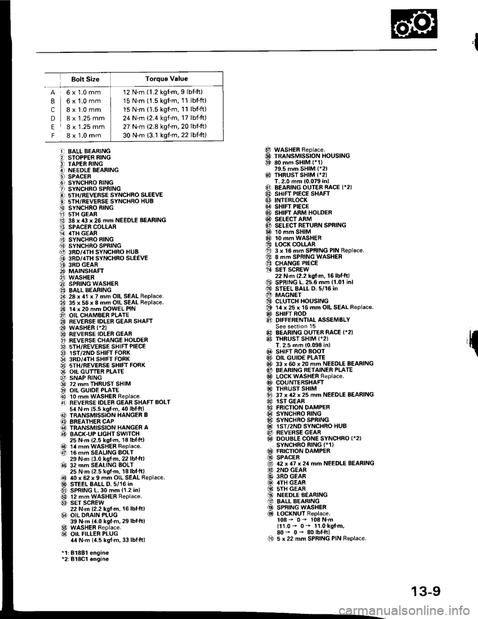
Bolt Size
,l
{
@@69
@
@@@@@@@@6Dq0
o€xv0@
@0!@@@@al
61@
B
c
D
E
F
6x1.0mm
6x1.0mm
I x 1.0 mm
8 x 1.25 mm
8 x 1.25 mm
8 x 1.0 mm
i) BALL BEARINGe sroPPER R|NG9 TAPER RINGA NEEDLE EEARINGO SPACER.d SYNCHRO RINGt sYNcHRo SPR|NG!) 5TH/REVEFSE sYNcHRo SLEEVEO 5TH/REVERSE SYNCHRO HUB[0 sYrucxao nlrucii i) 5TH GEARO 38 x 43 x 26 mm NEEDLE BEARINGt3 SPACEE COLLARO 4TH GEAR.iB SYNCHRO FING.Ii9 SYNCHRO SPRING{, 3RD/,ITH SYNCHRO HUB
@ 3RD/4TH SYNCHBO SLEEVEt9 3RD GEARO MAINSHAFTO wasHER@) SPRING WASHER40 BALL BEARINGO 28 x 41 x ? mm OIL SEAL Replace.ad 35 x 56 x 8 mm OIL SEAL Replace.a0 14 x 20 mm OOWEL PIN@ OIL CHAMBER PLATE'A BEVERSE IDLEN GEAR SHAFT@ wasHER t-2).A REVERSE IDLER GEAFO REVERSE CHANGE HOLDER3A sTH/REVERSE SHIFT PIECEO 1ST/2ND SHIFT FORK04 3RD/.TH sHlFr FoRK@ 5TH/REVERSE SHIFT FORKO9' OIL GUTTER PLATE6' SNAP RING@ 72 mm THRUST SHIM) OIL GUIOE PLATEi!0 10 mm WASHER Replace..4i] REVERSE IDLER GEAR SHAFT BOLT54 N.m {5.5 kgt m, 40lblftl) TRANSMISSION HANGER B(3 BREATHER CAP@ TRANSMISSION HANGER A63 BACK.UP LIGHT SWITCH25 N.m (2.5 ksf.m, 18lbfftl@r 14 mrn waSHER Replace.67 16 mm SEALING BOLT29 N.m (3.0 kgl.m, 22 lbf ft)@ 32 mm SEALING BOLT25 N.m (2.5 kgf.m. 18lbt'ft|@ 40 x 62 x 9 mm OIL SEAL Replace.D STEEL BALL D. 5/16 inGl SPRING L. 30 mm {1.2 in}
@ 12 mm WASHER Replace.63) SET SCREW22 N.m 12.2 kgl.m, 16 lbt'ft,@ OIL ORAIN PLUG39 N.m {4.0 kgt.m, 29 lbf'ftl€9 WASHER Replace.@ oIL FILLER PLUG4,1N.m 14.5 kgJ m, 33 lblftl
*1:81881 engine*2:B18Cl engine
WASHER Beplace.TRANSMISSION HOUSING80 mm SHIM (*1)79.5 mm SHIM {*21THRUST SHIM {*2IT. 2.0 mm (0.079 in)BEARING OUTER RACE {*2}SHIFT PIECE SHAFTINTERLOCKSHIFT PIECESHIFT ARM HOLDERSELECT ARMSELECT RETURN SPRING10 mm SHIM10 mm WASHERLOCK COLLAR3 x 16 mm SPRING PIN Replace.8 mm SPRING WASHERCHANGE PIECESET SCREW22 N.m {2.2 kgf.m, 16 lbf.ft}SPRING L.25.6 mm {1.01 inlSTEEL BALL D. 5/16 inMAGNETCLUTCH HOUSING14 x 25 x 16 mm OIL SEAL Replace.SHIFT RODDIFFERENTIAL ASSEMBLYSee section 15BEARING OUTER RACE I*2ITHRUST SHIM I*2)T. 2.5 mm (0.098 in,SHIFT ROD BOOTOIL GUID€ PLATE33 x 60 x 20 mm NEEDLE BEARINGBEARING RETAINER PLATELOCK WASHER Replace.COUNTERSHAFTTHRUST SHIM37 x 42 x 25 mm NEEDLE BEARINGlST GEARFRICTION DAMPERSYNCHRO RINGSYNCHRO SPRINGlST/2ND SYNCHRO HUBREVERSE GEARDOUBLE CONE SYNCHRO I*2ISYNCHRO BING I*1)FRICTION DAMPERSPACER42 x 6? x 24 mm NEEDLE BEARING2ND GEAR3RD GEAR4TH GEAS5TH GEARNEEDLE BEARINGBALL BEARINGSPRING WASHERLOCKNUT Replace.108 - 0- 108 N.m(11.0 - 0* 11.0 kgt m,80- 0- 80lbf.ft)5 x 22 mm SPRING PIN Replace.00
13-9
Page 352 of 1413
Transmission Housing
Removal
NOTE:
. lf the transmission housing or clutch housing a.ereplaced, the bearing proload must be adjusted(818C1 engine).
. Place the clutch housing on two pieces of wood thickenough to keep the mainshaft from the hitting the
workbench.
1. Remove the back-up light switch.
2. Remove the transmission hanger B,
3. Remove the set screws, the springs, and the steel
balls.
Tna sMtsstoN
SPBINGL. 30 mm11.2 inl
SET SCBEW
WASHERReplace.
4. Remov€ the reverse idler gear shaft bolt,
WASHERReplace.
REVERSE
L
13-10
ATTACHING BOLT
5. Loosen the transmission housing attaching bolts in
a crisscross pattern in several steps. then remove
them.TRANSMISSION
Remove the 32 mm sealing bolt.
Expand the snap ring on ths countershaft ball bear-
ing and remove it from the groove using a pair of
snap ring pliers.
32 mm SEALING BOLT
7.
SNAP RING
Page 353 of 1413

Reverse Change Holder,
Reverse ldler Gear
Clearance Inspection
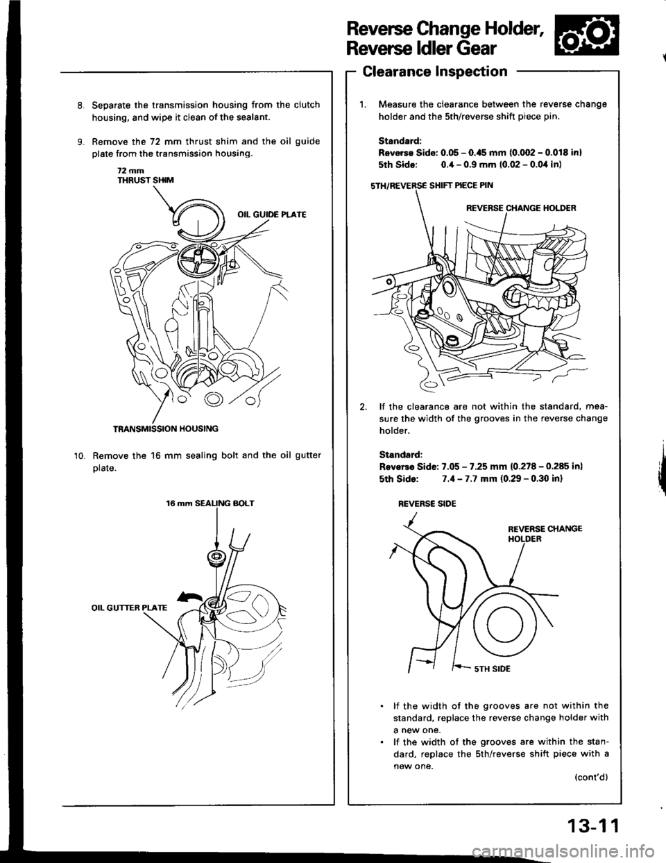
Measure the clearance between the re
holder and the sth/revsrse shift piece p
Standard:
Bevorse Sido: 0.05 - O.ils mm (0.002 - (
5th Sido: o.ia - 0.9 mm 10.02 - 0.0,1
SHIFT PIECE PIN
REVERSE CHANGE
€,
lf the clearance are not within the sti
sure the width of the grooves in the re
holder.
Standsrd:
Rovsrea Side: 7.05 - 7.25 mm {0.278 - (
sth Sido: 7.1-7.7 mm (0.29 - 0.30
REVERSC SIOE
REVERSE
I ' '-- sTH SIDE
lf the width of the grooves are n
standard, replace the reverse chan€
a new one.
lf the width of the grooves are wi
dard, replace the sth/reverse shift
new one,
Separste the transmission housing from the clutch
housing, and wipe it clean of the sealant.
Remove the 72 mm thrust shim and the oil guide
plate from the transmission housing.
t2 mmTHRUST SHIM
TRANSMISSION HOUSING
Remove the 16 mm sealing bolt and the oil gutter
plate.
OIL GUTTER PLATE
10.
reverse cnange
ptn.
.0.018 inl
),1in)
standard, mea-
reverse change
0.285 in)
I inl
not within the
Inge holder with
within the stan-
rift piece with a
(cont'd)
13-1 1
Page 378 of 1413
Clutch Housing Bearing
Replacement
Mainrhaft:
1. Remove the ball bearing using the special tools as
shown.
3/8' - 16 SI.IDE HAMMCR(commercially av6ilable)
CTUTCH
ADJUSTABIT AEARINGPULER, 25 - a0 mrn07736 - A01moA
2. Remove the oil seal from the clutch housing.
CLUTCH HOUSING
3. Drive the new oil seal into the clutch housing using
the specialtools as shown.
ATTACHMEIVT, a2 x 4t rnm0r7a5 - 0010300
()|L SEAIRoplacs.
Drive the ball bearing into the clutch housing usin!
the sDecial tools as shown.
13-36
BATI. BEAMIO
Page 388 of 1413

Transmission Assembly
1. Inst€llthe dowel pins on the clutch housing.
2. Apply grease to the parts as shown, then install the
release fork and release beaaing.
NOTE: Use only Super High Temp Urea Grease(P/N 08798 - 9002).
3. Install the release fork boot.
lnstallation
22 tbt-ttl
BELEASE FORK BOLT29 N.m (3.0 kgl.m,tPlN 08798 - 90021
RELEASEBEARING
@
I
{P/N 08798 - 90021
Place the transmission on the transmission iack,
and raise it to the engine level.
Install the transmission mounting bolts and the rear
mount bracket bolts sELF-LocKrNG BoLT
RELEASE REEASEFORK FORKBOOT
12 x 1.25 mm6it N.m 16.5 kgl.m, 47 lbf.ftl
Replace.14 x 1.5 mm
13-46
6, Raise the transmission, then install the transmission
mounI.
NOTE: Torque the mounting bolt and nuts in the
sequence shown.
CAUTION: Check that the bushings are not twistod
or offset,
O 12 x 1.25 mm54 N.m {6.5 kgt m,47 tbtfrl
7. Install the three upper transmission mounting
and lower starter motor mounting bolt.
bolts
10 x 1.25 mm44 N.m lil,s kgt m,33 tbf.ftl
@ 12 x 1.25 mm7,1 N.m 17.5 kg{.m,5/r lbtftl
12 x 1.25 mm64 N.m 16.5 kgf.m, 47 lbf.ftl
Page 389 of 1413

8, Instsll the right tront mounvbracket.
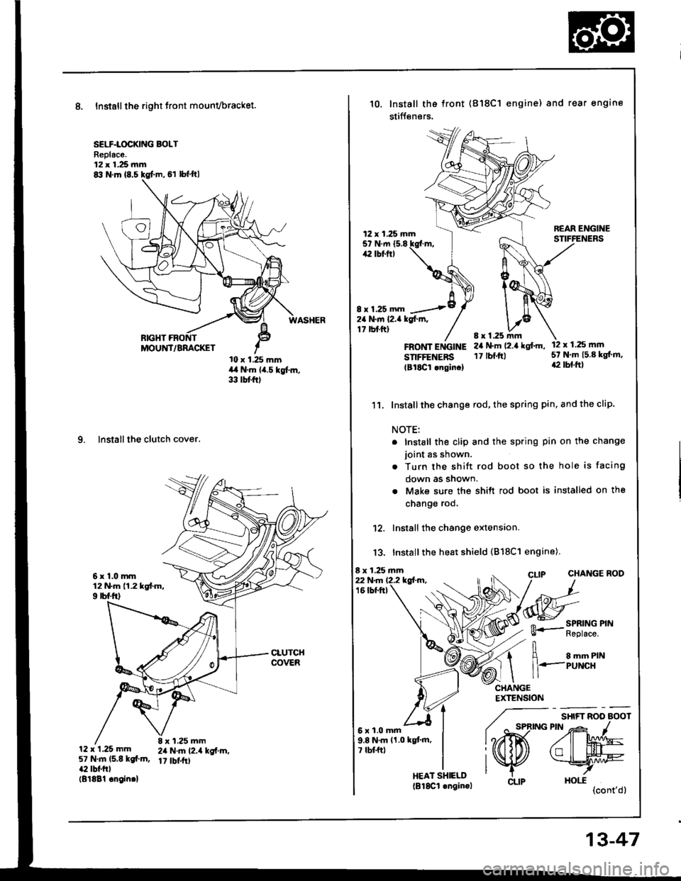
SELF.LOCKING BOLTReplac€.12 x 1.25 mm
10 x 1,25 mmil a N.m (i4.5 kgf..n,33 tbtftl
9. Installthe clutch cover.
6r1.0mm12 N.m 11.2 kgtm,9 rbf.ftl
12 x 1.25 mm57 N.m ls.E kgf.m,a:I lbl.trll818Bl .ngin.l
8 x 1.25 mm2il N'm 12.4 kg{.m,17 tbffrt
RIGHT
10.lnstall the tront
stiff€nsrs.
(818C1 engine) and rear engine
8 x 1.25
12 x 1.25 mm5t N.tn {5.842 tbt ftt
24 N.m l2.a kgf.]n,17 tbtftl
8 x 1.25 mm
22 N.rn 12.2 kgl-m.16 tbtftl
FROifT ENGINE 2r N'm (2.4 kg['m,
SnFFENERS 17lbf.ttl
lBl8Cl lngin.l
11. Installthe change rod, the spring pin, and the clip.
NOTE:
12 x 1.25 ftm5? N.rn l5.E kg[.m,42 tbl.ft)
sHtFT ROO aOOt
2MqlL#--7
HOt.C(cont'dl
. Install the clip and the spring pin on the
joint as shown.
. Turn the shift rod boot so the hole is
down as shown.
. Make sure the shift rod boot is installed
cnange roo,
12. Install the change extension.
13. Installthe heat shield (818C1 engine).
8 x 1.25 mm
change
facing
on the
CHANGE ROD
CHANGEEXTENSION
5xl.0mm9.8 N.m 11.0 kgt'm,7 tbf.ftt
/^ "-*
i@
CLIP
. SPRING PINl3- Replace.
I e -- nrr,l
ll'--PuNcH
HEAT SHIELD(B18Cl .nginol
13-47