Page 54 of 1413
31. Remove the shift cable
I x 1.25 mm22 f.m 12.2 kgl'rn'16 tbl.ftl
(A/T).
SHIFT CABLE
32.
33.
CONTROLLEVER
SHIFT CAALEcovER locx usiea6 x 1.0 mm14 N.m t1.4 kgf.m, 10 lbl'ftlReplace.
Remove the damper tork.
Disconnect the suspension lower arm balljoints us-
ing the special tool. Refer to section 1 8 tor the proper
procedure.
NOTE: Adjust the tool so the iaws are parallel to
each other.
REMOVER 28 mmoTMAC-S10020012 x 1.25 mm
5-9
34. Remove the driveshatls.
CAUTION:
a Do not pull on tho ddv$halt, tho CV ioint mav
como apan.
a Uso caro whsn prying out tho assombly.
Pult it slraight to avoid damaging th6 differantial
oil soal or intormodiato shaft dust seal.
NOTE: Coat all precision tinished surfaces with
clean engine oil or grease. Tie plastic bags over the
driveshaft ends.
(cont'd)
Page 201 of 1413
ENGINECOOLANT
@ FUEL TAI{K EVAPORATIVE EMISSION (EVAP} VALVE
G) FUEL PULSATION DAMPER
@ AIR CLEANER
@) RESONATOR
@ THREE WAY CATALYTIC CONVEnTER (TWC)
o POS|TIVE CRANKCASE VEITITILAT|ON IPCV) VALVE
@ EVAPOBATIVE EMISSION IEVAP) COI{TROL CANISIER
@ EvApoRATrvE EMrssroN IEVAP) PURGE coNTRoL
SOLENOID VALVE
@ EVAPORATTVE EMISSION (EVAP) PURGE CONTROL
DIAPHRAGM VALVE(iD EVAPORATIVE EMISSION (EVAPI TWO WAY VALVE
|l
U]
HEATED OXYGEI{ SEI{SOF (HO2S}
MANIFOI.D ABSOLUTE PRESSURE (MAP) SEI{SONENGINE COOLANT TEMPERATURE IECT} SENSORINTAKE AIR TEMPERATURE IIAT} SEI'ISORIDLE AIR CONTROL IIAC) VALVEFAST IDLE THERMO VALVEFUEL II{JECTORFUEL FILTERFUEL PRESSURE REGULATONFUEL PUMP IFP)FUEL TAI{K
11-9
Page 203 of 1413
G) FUEL PUI-SATION DAMPER
@ AIR CLEANER(D RESONATOR6 imrlre arR Bypass (tAB) coNTRoL DIAPHRAGM
VALVE(D) IITITP IIN BYPASS {IAB) COTROL SOLENOID VALVE
ds) INTIXT AIR EYPASS TIABI VACUUM TANK
rio'l rnrarg ltn BYPASS (lABl cHEcK vALvE
6 rsnee wav cATALYTtc coNvERTER lrwc)
6 posrnve cRAf{KcAsE vENTILATIoN {Pcv) vALVE
6 evlponlrtve EMtsstot{ tEvAPl coNTBoL cANlsrER
6 evlponltvE EMtssloN {EvAP} PURGE coNTRoL
SOLENOID VALVE6i EVAPORATIV€ EMISSION (EVAPI PURGE CONTROL
DIAPHRAGM VALVE
6o ivlpoalrtve Eutsstof{ IEVAPI rwo wAY vALvE
c) HEATED OXYGEN SENSOR lHO2Sl
€) MANIFOLD ABSOLUTE PRESSURE IMAPI SENSOB
O EI{GINE COOLANT TEMPERATURE {ECT} SENSOR
€) INTAKE AIR TEMPERATURE {IAT) SENSOR
@ KNOCK SENSOR tKSl
@ IDLE alR coNTRoL llAcl vALvE
O FAST IDLE THERMO VALVE
@ FUEL INJECTOR
@ FUEL FILTER
@ FUEL PRESSURE REGULATOR
O) FUEL PUMP (FPI
@) FUEL TANK
@ FUEL TANK EVAPORATIVE EMISSION IEVAPI VALVE
11-11
Page 289 of 1413

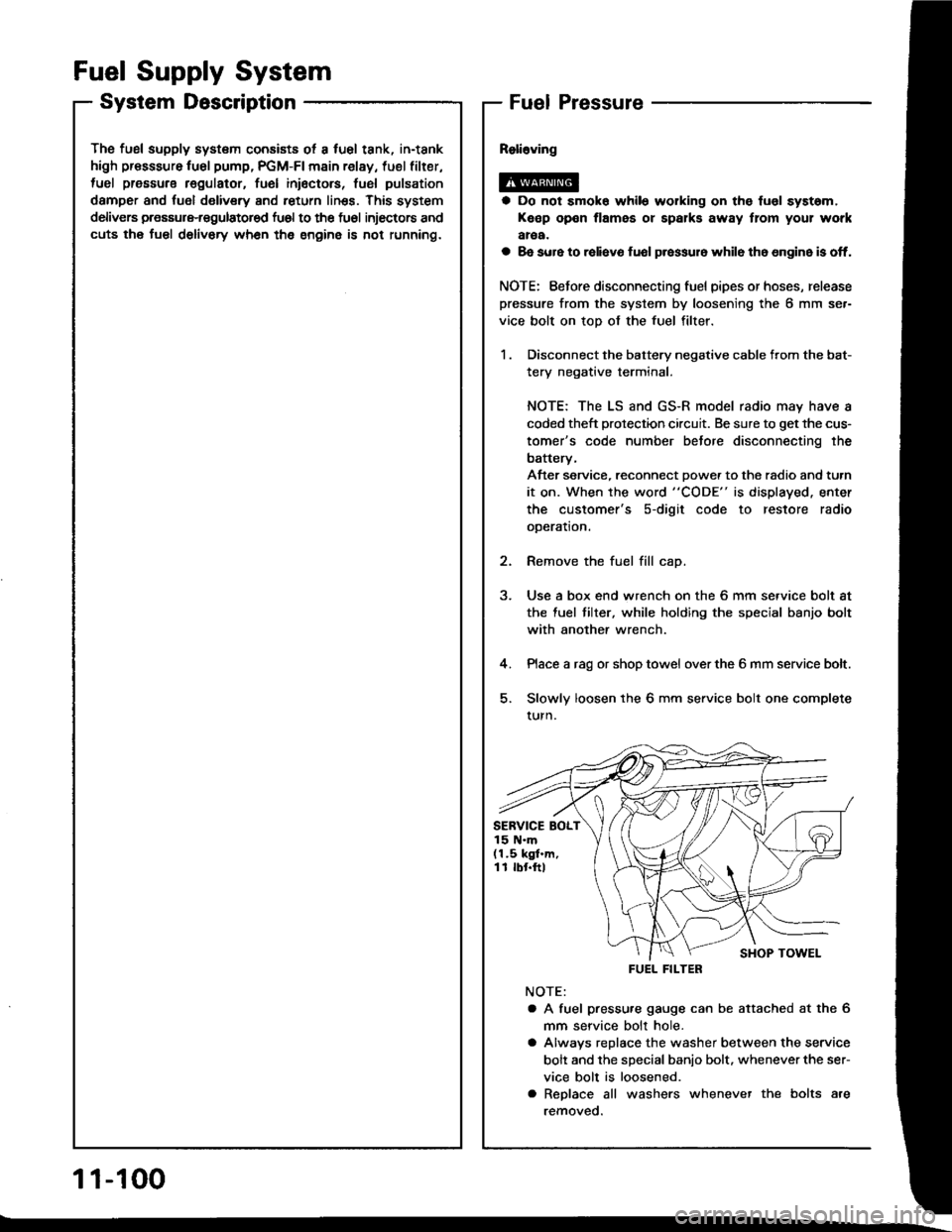
The fusl supply system consists ot a fuel tank, in-tank
high presssure fu6l pump, PGM-FI main relay, fuel filter,
tuel pressure regulatot, fuel inioctors, fusl pulsation
damper and fuol delivery and return linss. This system
delivers pressure-regulatored fu6l to the fu6l injectors and
cuts the fuel delivory wh6n the engine is not running.
Fuel Supply System
System DescriptionFuel Pressure
a Do not smok6 while working on the fuol syst6m,
Keep open flames or spalks away tlom your work
aroa.
a 8e sure to raliavo fuol p.essur6 while th6 6n9in6 is off.
NOTE: Eefore disconnecting fuel pipes or hoses, release
pressure from the system by loosening the 6 mm se.-
vice bolt on top of the fuel filter.
1 . Disconnect the battery negative cable from the bat-
tery negative terminal.
NOTE: The LS and GS-R model radio may have a
coded theft protection circuit. Be sure to get the cus-
tomer's code number betore disconnecting the
batterv,
After service, reconnect Dowe. to the radio and turn
it on. When the word "CODE" is displayed. enter
the customer's s-digit code to restore radio
ooeration.
2. Remove the fuel fill cap.
3. Use a box end wrench on the 6 mm service bolt at
the fuel tilter, while holding the special banjo bolt
with another wrench.
4. Place a rag or shop towel over the 6 mm service bolt.
5. Slowly loosen the 6 mm service bolt one complete
turn.
NOTE:
a A fuel pressu.e gauge can be attached at the 6
mm seryice bolt hole.
a Alwavs replace the washer between the service
bolt and the special banio bolt. whenever the ser-
vice bolt is loosened.
a Replace all washers whenever the bolts are
removeo.
SERVICE BOLT15 N.m(1.5 kgf.m,11 rbr.ftl
FUEL FILTER
1 1-100
Page 335 of 1413
Clutch Master Cylinder
Removal/lnstallation
CAUTION:
a Do not sgill b.ake lluid on the car; it may damags the
painl; it biake fluid does contact tha paint. wash it
otf immediately with water.
a Plug lhe end ot the clutch pips and r€servoil hose with
a shop towel to prsvent blake fluid ttom coming out.
1. Remove the brake fluid from the clutch master
cylinde. reservoir with a syringe.
2. Disconnect the clutch oioe and reservoir hose from
the clutch master cvlinder.
CLUICH PIPE15 N'm {1.5 kgl.m,1 1 tbf.ftl
CLUTCHMASTERCYLINDER
Pry out the cotter pin. and pull the pedal pin out ot
the yoke. Remove the nuts.
NUTS13 N.m {1.3 kgf.m,9 lbt.frl
Remove the clutch master cylinder.
NOTE: Do not spill brake fluid on the
cylinder damper.
OAMPERCLUMAIcYL
Install the clutch master cylinder in
der of removal.
NOTE: Bleed the clutch hydraulic s\
12-61.
clutch master
CLUTCHMASTERCYLINDER
!l rn Ine reverse or-
c system (see page
12-5
Page 351 of 1413

12 N.m (1.2 kgim,9 lbnft)
15 N.m (1.5 kgnm, 11 lbf.ft)
15 N.m (1.5 kgf.m, 11 lbf.ft)
24 N.m (2.4 kgf.m, 17 lbf'ft)
27 N.m (2.8 kgnm,20 lbnft)
30 N.m (3.1 kgf.m, 22 lbf'ft)
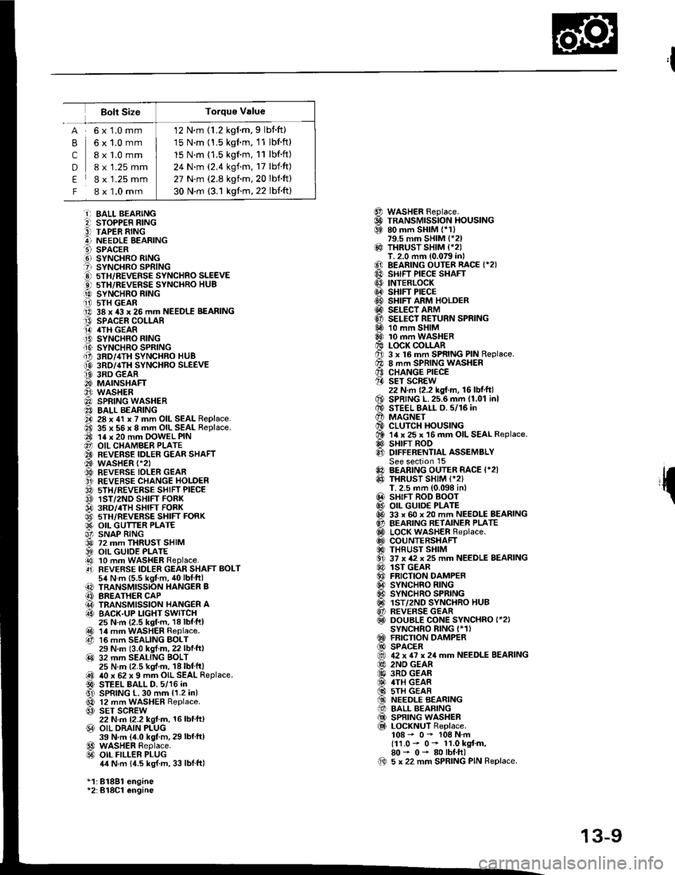
Bolt Size
,l
{
@@69
@
@@@@@@@@6Dq0
o€xv0@
@0!@@@@al
61@
B
c
D
E
F
6x1.0mm
6x1.0mm
I x 1.0 mm
8 x 1.25 mm
8 x 1.25 mm
8 x 1.0 mm
i) BALL BEARINGe sroPPER R|NG9 TAPER RINGA NEEDLE EEARINGO SPACER.d SYNCHRO RINGt sYNcHRo SPR|NG!) 5TH/REVEFSE sYNcHRo SLEEVEO 5TH/REVERSE SYNCHRO HUB[0 sYrucxao nlrucii i) 5TH GEARO 38 x 43 x 26 mm NEEDLE BEARINGt3 SPACEE COLLARO 4TH GEAR.iB SYNCHRO FING.Ii9 SYNCHRO SPRING{, 3RD/,ITH SYNCHRO HUB
@ 3RD/4TH SYNCHBO SLEEVEt9 3RD GEARO MAINSHAFTO wasHER@) SPRING WASHER40 BALL BEARINGO 28 x 41 x ? mm OIL SEAL Replace.ad 35 x 56 x 8 mm OIL SEAL Replace.a0 14 x 20 mm OOWEL PIN@ OIL CHAMBER PLATE'A BEVERSE IDLEN GEAR SHAFT@ wasHER t-2).A REVERSE IDLER GEAFO REVERSE CHANGE HOLDER3A sTH/REVERSE SHIFT PIECEO 1ST/2ND SHIFT FORK04 3RD/.TH sHlFr FoRK@ 5TH/REVERSE SHIFT FORKO9' OIL GUTTER PLATE6' SNAP RING@ 72 mm THRUST SHIM) OIL GUIOE PLATEi!0 10 mm WASHER Replace..4i] REVERSE IDLER GEAR SHAFT BOLT54 N.m {5.5 kgt m, 40lblftl) TRANSMISSION HANGER B(3 BREATHER CAP@ TRANSMISSION HANGER A63 BACK.UP LIGHT SWITCH25 N.m (2.5 ksf.m, 18lbfftl@r 14 mrn waSHER Replace.67 16 mm SEALING BOLT29 N.m (3.0 kgl.m, 22 lbf ft)@ 32 mm SEALING BOLT25 N.m (2.5 kgf.m. 18lbt'ft|@ 40 x 62 x 9 mm OIL SEAL Replace.D STEEL BALL D. 5/16 inGl SPRING L. 30 mm {1.2 in}
@ 12 mm WASHER Replace.63) SET SCREW22 N.m 12.2 kgl.m, 16 lbt'ft,@ OIL ORAIN PLUG39 N.m {4.0 kgt.m, 29 lbf'ftl€9 WASHER Replace.@ oIL FILLER PLUG4,1N.m 14.5 kgJ m, 33 lblftl
*1:81881 engine*2:B18Cl engine
WASHER Beplace.TRANSMISSION HOUSING80 mm SHIM (*1)79.5 mm SHIM {*21THRUST SHIM {*2IT. 2.0 mm (0.079 in)BEARING OUTER RACE {*2}SHIFT PIECE SHAFTINTERLOCKSHIFT PIECESHIFT ARM HOLDERSELECT ARMSELECT RETURN SPRING10 mm SHIM10 mm WASHERLOCK COLLAR3 x 16 mm SPRING PIN Replace.8 mm SPRING WASHERCHANGE PIECESET SCREW22 N.m {2.2 kgf.m, 16 lbf.ft}SPRING L.25.6 mm {1.01 inlSTEEL BALL D. 5/16 inMAGNETCLUTCH HOUSING14 x 25 x 16 mm OIL SEAL Replace.SHIFT RODDIFFERENTIAL ASSEMBLYSee section 15BEARING OUTER RACE I*2ITHRUST SHIM I*2)T. 2.5 mm (0.098 in,SHIFT ROD BOOTOIL GUID€ PLATE33 x 60 x 20 mm NEEDLE BEARINGBEARING RETAINER PLATELOCK WASHER Replace.COUNTERSHAFTTHRUST SHIM37 x 42 x 25 mm NEEDLE BEARINGlST GEARFRICTION DAMPERSYNCHRO RINGSYNCHRO SPRINGlST/2ND SYNCHRO HUBREVERSE GEARDOUBLE CONE SYNCHRO I*2ISYNCHRO BING I*1)FRICTION DAMPERSPACER42 x 6? x 24 mm NEEDLE BEARING2ND GEAR3RD GEAR4TH GEAS5TH GEARNEEDLE BEARINGBALL BEARINGSPRING WASHERLOCKNUT Replace.108 - 0- 108 N.m(11.0 - 0* 11.0 kgt m,80- 0- 80lbf.ft)5 x 22 mm SPRING PIN Replace.00
13-9
Page 370 of 1413
Countershaft Assembly
lndex
NOTE:
3
The 4th and 5th gears are installed with a press.
Prior to reassembling. clean all the pans in solvent, dry them and apply lubricant to any contact surfaces. The 4th
and sth gears. however, should be installed with a press before lubricating them.
LOCKNUT ReDlace.l(E*0*10EN.m
/r1.0 - 0 - 11.0 kgtm,Il8o- o-80rbf.ft I
WASHER
BALL BEARINGInspect for wearand operat|on,
NEEDLE BEARINGInspect Ior wearand operation.
sTH GEAR
4TH GEAR
3RD GEAR
2ND GEAR
NEEDLE BEARINGInspect for wearand operation.
SPACERSelection. page 13-29
FRICTION DAMPER
DOUB1I @NESYNCHRO l818Cl .ngin.lInspection, page 13-35SYNCHRO RING lBl8Bl .ngin )Inspection, page 13-35
SYNCHRO SPBING
SYNCHRO RING
THRUSTBEARING
13-24
Page 374 of 1413

Countershaft Assembly
Reassembly
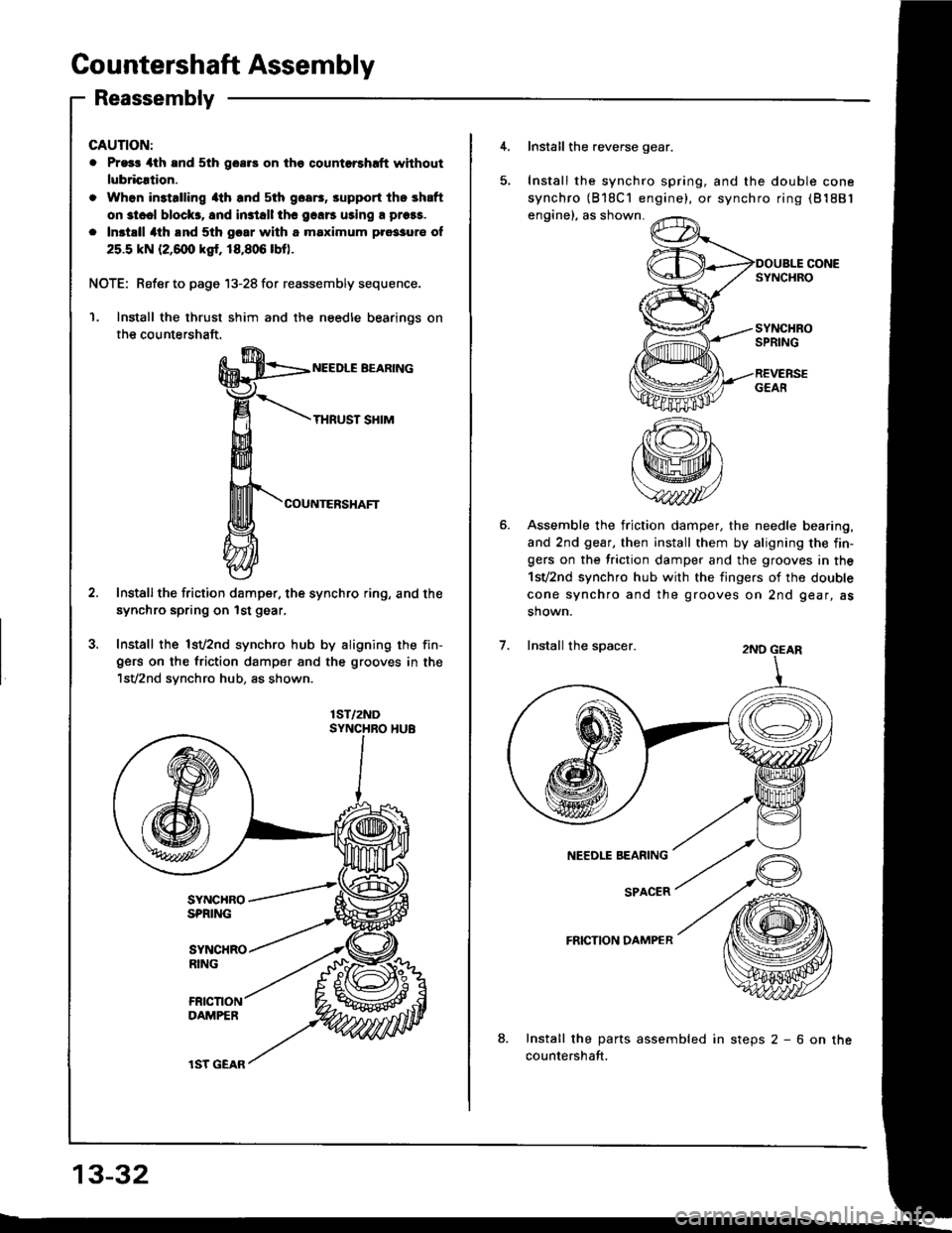
GAUTION:
. Pr93r 4th and 5th goar3 on the qountorshrft without
lubricrtion.
. Whon in3talling 4th and sth goa6, srpport the shaft
on st..l block3, 8nd in3tall thc 9.116 uring a prors.
. Inst.ll 4th lnd 5th gcar with a maximum pro33ur€ of
25.5 kN (2,6@ ksr. 18,806 lbo.
NOTE: Refer to page 13-28 for reassembly sequence.
Install the thrust shim and the needle bearinos on
the countershaft.
NEEDLE BEARING
THRUST SHIM
COUNTERSHAFT
Installthe friction damper. the synchro ring, and the
synchro spring on lst gear,
Install the lsv2nd synchro hub by aligning the fin-gers on the friction damper and the grooves in the'lsV2nd synchro hub, as shown.
1ST/2ND
13-32
lST GEAR
4. Install the reverse gear.
Install the synchro spring, and the double cone
synchro (818C'l engine), or synchro ring (81881
engine), as shown.
SYNCHROSPRING
REVERSEGEAfi
Assemble the friction damper, the needle bearing,
and 2nd gear, then install them by aligning the fin-gers on the friction damper and the grooves in the
1sv2nd synchro hub with the fingers of the double
cone synchro and the grooves on 2nd gear, as
shown.
2ND GEAR
NEEDLE BEARING
SPACER
FRICTION DAMPER
8.Install the parts assembled in steps 2 - 6 on the
countershaft.
Install the spacer.