1993 VOLKSWAGEN GOLF manual radio set
[x] Cancel search: manual radio setPage 7 of 156
Downloaded from www.Manualslib.com manuals search engine __CONTROLS AND EQUIPMENT
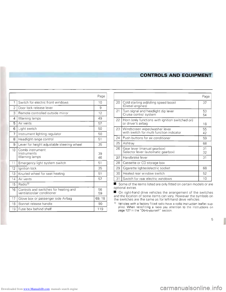
Page
1 Switch for electric front windows 10
2 Door lock release lever 9
3
Remote controlled outside mirror 12
4 Warning lamps 49
5 Air vents 57
6 Light switch 50
7 Instrument lighting regulator 50
8 Headlig ht range control 51
9 Lever for heig ht adjustable steeri ng w heel 35
1 0
Combi instrument:
Instruments
Warning lamps
39
46
1 1 Emer gency light system switch 51
' 2 Ignition lock 35
' 3
Knurled wheel for seat heating 51
'4 A ir ve nts 57
' 5 Radio 1)
·6 Controls and switches for heating and
ventilation/air conditioner 56
59
17 Glove box or passenger side Airbag 69,1 8
18 Bonnet release handle 90
'9 Fuse box behind shelf 119
Page
20 Cold starting aid/idling speed boost (Diesel engines) 37
21 Turn signal and headlight dip lever
Cruise control system 53
54
22 Horn (on ly functions with ign ition switched on)
or driver's airbag 18
23 Windscreen w iper/washer lever
w ith switch for multi function indica tor 55 42
24 Push buttons for air conditi oner 59
25 Ash tray 68
26 Gear lever (manua l ge arbox) Sel ector lever (automa tic gea rbox) 31 32
Xl-Handbrake leve r 31
28 Cassette or CD storage box
29 Cigarette lighter/elec tric soc ket 68
30
Heated rear windo w switch 52
31 Switch for rear electric w indows 10
• Some of the items listed are only fitted on certain models or are op tional extras .
• On right-hand drive vehicles the
arrangement of the switches
and the location of some items can vary. However the symbo ls on
th e switc hes are the same as for left-hand drive vehic les.
n Vehicl es with a facto ry fitted radio have a rad io ins truction le aflet supplied Whe n re trof ittin g a radio pay atte ntion to the instructions on
page 127 in the" Do-it-yours elf " sect ion.
5
Page 43 of 156
Downloaded from www.Manualslib.com manuals search engine CONTROLS AND EQUIPMENT
2 -Analog clock
--e th e time there is a button below the
_ -(right arrow):
• -pr esse d briefly , the
time is advanced one minute.
• pressed continuous ly the minute hand
ss fa ster and the hours are set as well.
;h the button the clock can be set exactly
- h e second :
• Press button until
time is one minute be.,re ti me to be set.
• ress button at the
moment when the
_ =f'"on ds indicator of an accurate clock -~ows a full minute or when the time signal
s eard on the radio.
2-Rev counter *
- e rev counter needle mu st not move into
e red zone of the sca le on any account.
~Changing up in good time helps ~,) to save fuel and keeps the noise down.
_hange down to the next lower gear before ~"e engine starts labouring or no longer runs
l oothly.
rin g the running-in period, high engine ' 9VS should be avoided.
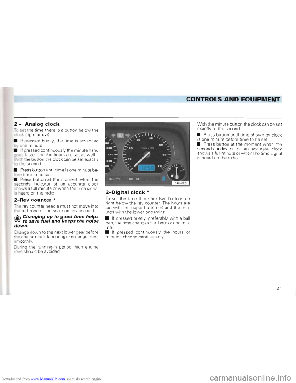
2-Digital clock *
To set the time there are tw o buttons on right below the re v counter . The hours are
set with the upper button (h) and the min
utes with the lower one (min) :
•
If pressed briefly, preferably w ith a ball
pen, the time changes one hour or one min
ute.
• If pressed continuous ly the hours or
m inutes change continuous ly . With
the minute button the clock
can be set
exactly to the second:
• Press button until
time shown by clock is one mi nute before time to be set.
• Press button at the moment w he n the
seconds indicator of an accurate clock
shows a fu ll minute or when the time signa l
i s heard on the radio.
41
Page 66 of 156
Downloaded from www.Manualslib.com manuals search engine CONTROLS AND EQUIPMENT
Operating instructions
• Ensure that the sensor betvveen the
windscreen defrost outlets in the centre of
the instrument panel and the air grille next
to the radio is not covered.
• If, after switching on the ignition,
all sym
bols in the display area flash for about 15
seconds, there is a fault in the system -con
tact a Volkswagen dealer.
Notes for both air conditioning
systems
• To ensure that the heating, ventilation
and air conditioner can work properly, the air
inlet in front of the windscreen should be
kept free of ice, snow and leaves.
• The heat output depends
on the coolant
temperature -the full heat output is there
fore available when the engine IS warm.
• The stale air escapes through openings
in the luggage compartment side panels.
Therefore when loading the luggage com
partment ensure that the openings are not
covered .
• When the ambient temperature
is high
and the air very humid, condensed water can drip off the evaporator and form a
puddle under the vehicle. This is quite nor
mal and does not indicate a leak.
Notes for the normal air condi
tioner
• All controls except the rotar y switch A and buttons 0 and E can be set to any inter
mediate position.
•
To prevent the windows from misting up
the blower should be running slowly when driving at low speeds.
Using air conditioners economi
cally
In cooling operation the air conditioner com
pressor places demands on the engine and
therefo re influences the fuel consumption.
To keep the period switched on as short as possible, the following points should be
noted:
• If the
in side temperature is very high
after the car has been parked in the sun, it is recommended to open doors or windows briefly to enable the hot air to escape
• The air conditioner should not be
switched on during a Journey if the
windows or sliding/tilting roof* are open.
• If the desired interior temperature
can be attained w ithout switching on the air
cond itioner the fresh air operation should
be selected (does not apply to Climatronicl.
Operating faults
• Should the air cond i:ioner not work at
any time, either .
- the ambient temperatu re IS below about +5 °C,
-or the fuse has blown.
Check fuse and if necessary r
enew it - see
page 119. If the troub le is n ot due to a defec
tive fuse, SWitch the system off and have It
checked.
- the air conditioner
has svvitched off due
to coolant temperature being too high -see
page 45.
• If the cooling output drops off, switch
the AlC
off and have the system checked.
64
Page 122 of 156
Downloaded from www.Manualslib.com manuals search engine DO-lT-YOURSELF
Fuse layout
(from left to rig ht)
No. Component A 1)
1 Dipped beam left,
headlight range control left 10 2 Dipped beam right,
head light ra nge co ntrol right 10 3 Instrument and number plate
light ing . 10 4 Rear w iper, slid ing/tilti ng roo f, 15
5 Windscreen w ipe r, windscr een
a
nd rea r w indo w was her,
ele c. heated windsc reen washer
jets . . . . . . 15
6 Blower,
air co nditi oner ... . 30
7 Tail and side light ri ght 10
8 Tail and side light left . . 10
9 Rear window heating , mirror
heating ... 20 10 F og lights, rear fog light 15 11 Main beam left, main beam
w arnin g lamp 10
12 Mai n bea m right . 10
13 Horn, radiator fan (run- on) . 10
14 Reve
rsi ng lights, electric out
side mirrors, seat heating,
elec. w ind ows,
air conditio ne r
cruis e contro l system 15
No. Component Amp. 1)
15 Engine elec tronics , cool ant
c irculat ion run- on pump,
(six cylinder engine)
.. . .. .. . . . 10
16
Warning lamps, glove box light,
cas sette sto rage box light, 15
17 T urn sig nals. . . . . . . . . . . . .. 10 18 Electri c fue l pum p,
Lambda probe ..... .. ....... 20
1 9 Radiat or fan, air cond itioner. . 30
20 Brake lights, cruise control
syste m (tri gger conta cts
on brake and clutch pedals) . 10 21 Interior and luggage compart
ment lights, clock, cigarette lighter,
ce ntral
locking, multi -function
indicator 15 22 Radio 10
Automatic fuse
All electric windows are protected to
ge ther via an automatic fu se (see rig ht -hand
co lum n) which breaks the circuit when
overloaded (e .g. windows frozen) and makes the circuit again after a few seconds.
Additional fuses
(in separate holders)
• above the
rela ys:
Fu se for ABS motor re lay. ..... . .... 30
Fuse for ABS main relay. ... 30
Fuse for normal air conditioner 10
Fuse for fresh air blower on
Climatronic ... ... ... . 30
Fuse for C1imatronic .. .... ... 5
Automatic fuse for electric w indo ws .. 20
Trailer perma nent + 15
• in the engin e compa rtment on the bulk
head above the brake servo:
Diesel glow plugs 21 . . 50
Fuse colour code:
Light brown :
5 Amper e
Red: 10 Ampere Blue: 15 Ampere Yellow 20 Ampere Green 30 Ampere
21 This fuse shou ld onl y be renewed by a Volks wagen dea ler.
1) Amper e
120
Page 129 of 156
Downloaded from www.Manualslib.com manuals search engine DO-lT-YOURSELF
Installing radio
When service installing a radio or replacing
a set installed by the factory the following
points should be noted
• The connection "
in the vehicle is for
Genuine Volkswagen radiosll from Model Year 1994.
• Radios with oth er con nections must be
connected with a n adapter cab le which can also be obtained from a Volkswagen dealer.
Attention On no account cut wires off and leave them without insulation. If necessary use a proper adapter. Otherwise the wiring can be overloaded or short circuits can occur -Fire danger!
11 Not availab le i n all export mark ets
Apart from this, important electronic components can be damaged or the functioning impaired. If for example the speed signal is disturbed this can lead to faulty engine management, automatic gearbox, ABS etc.
Even connecting the speed signal to radio sets with speed dependent volume control from other manufacturers can cause such faults.
• It is advisab le therefore to have the in
sta llation of the radio system done by a Volkswagen dealer. They are fully informed
about the technical features of the vehicle,
have the Genuine radios
1), the necessary
fitting parts from the Genuine Volksvvagen
Accessory Programme 1
) and work in ac
cordance with the guidelines developed by
the factory . •
The radios from the Genuine Volk
swa gen Accessory Programme
1
) are similar
to those used in the factory and ensure
trouble-free Installation .
These sets are
in keeping with the advanced technology and well-planned easy
to-operate design.
In Germany there is also an Exchange Ser
vice for the se radios so that even after years
of use a set requir ing repair
can be ex
changed cheaply for a completely recondi
tioned, good-as-new set by a Volkswagen
dealer.
• Loudspeakers, fitting parts, aerials and
supp
ression kits shou ld also be taken from
the Genuine Volkswagen Accessory Pro
gramme1) These parts have all been
specially developed for each vehicle model.
127