1993 VOLKSWAGEN CORRADO technical data
[x] Cancel search: technical dataPage 690 of 920

SCHEDULED SERVICES
Article Text (p. 8)
1993 Volkswagen Corrado
For Volkswagen Technical Site: http://vw.belcom.ru
Copyright © 1998 Mitchell Repair Information Company, LLC
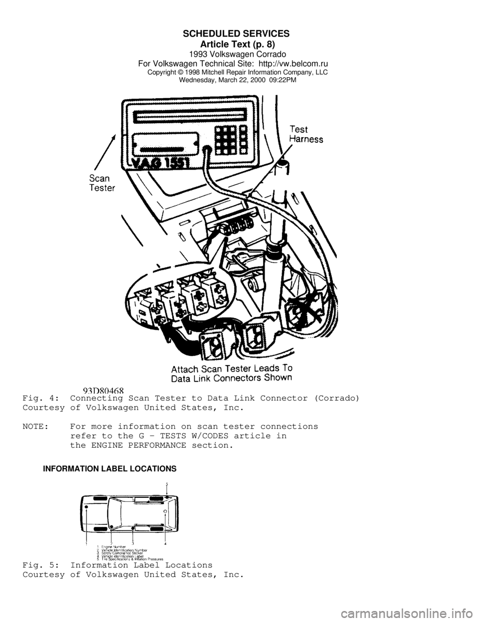
Wednesday, March 22, 2000 09:22PMFig. 4: Connecting Scan Tester to Data Link Connector (Corrado)
Courtesy of Volkswagen United States, Inc.
NOTE: For more information on scan tester connections
refer to the G - TESTS W/CODES article in
the ENGINE PERFORMANCE section.
INFORMATION LABEL LOCATIONSFig. 5: Information Label Locations
Courtesy of Volkswagen United States, Inc.
Page 725 of 920

SPECIFICATIONS & ELECTRIC COOLING FANS
Article Text (p. 2)
1993 Volkswagen Corrado
For Volkswagen Technical Site: http://vw.belcom.ru
Copyright © 1998 Mitchell Repair Information Company, LLC
Wednesday, March 22, 2000 09:23PM
fan is not coming on at proper temperature and engine is
overheating.
Corrado SLC, Passat GLX
The cooling fan is either a 1 or 2-speed motor. If vehicle is
equipped with single-speed motor, the fan comes on at 198-207øF (92-
97
øC) and turns off at 183-196øF (84-91øC). If equipped with a 2-speed
motor, low speed of cooling fan should come on at 198-208
øF (92-98øC)
on vehicles without A/C, or 183-207
øF (84-97øC) on vehicles with A/C.
Low speed will shut off at 183-196
øF (84-91øC) on all vehicles. High
speed comes on at 210-226
øF (99-108øC) on vehicles without A/C, or
201-226
øF (94-108øC) on vehicles with A/C. High speed will shut off at
196-220
øF (91-104øC) on all vehicles.
After-Run Thermoswitch
An after-run switch is used to help prevent fuel
vaporization. The thermoswitch turns cooling fan on when temperatures
in engine compartment exceeds 230
øF (110øC), and turns it off at 217øF
(103
øC).
Passat GL
The cooling fan is a 2-speed motor. Low speed of cooling fan
should come on at 198-207
øF (92-97øC) and will shut off at 183-196øF
(84-91
øC). High speed comes on at 210-221øF (99-105øC) and will shut
off at 196-208
øF (91-98øC).
TROUBLE SHOOTING
NOTE: Trouble shooting information not available from manufacturer.
TESTING
ENGINE COOLANT TEMPERATURE (ECT) SENSOR
Corrado SLC & Passat GLX (2.8L)
1) Ensure engine is cold. Connect Scan Tester (VAG 1551) to
Data Link Connectors (DLC) located in center console, in front of
shift lever.
2) Start engine and allow it to idle. With scan tester in
READ TEST VALUE BLOCK function, select group No. 01 and read coolant
temperature value in field No. 2 of scan tester. Temperature value
must increase uniformly without interruption. If value increases as
specified, select END OUTPUT function on scan tester.
3) If displayed value does not change or if engine
malfunctions during certain temperature ranges, turn ignition off and
measure engine coolant temperature sensor resistance. See ECT SENSOR
LOCATION table. Replace ECT sensor if resistance is not within
specification. See ECT SENSOR RESISTANCE table.
Passat GL
1) Ensure engine is cold. Connect Scan Tester (VAG 1551) to
Data Link Connectors (DLC) located in center console. Start engine and
Page 761 of 920

VR65 ENGINE: AFFIX NEW VACUUM HOSE ROUTING LABEL
Article Text (p. 2)
1993 Volkswagen Corrado
For Volkswagen Technical Site: http://vw.belcom.ru
Copyright © 1998 Mitchell Repair Information Company, LLC
Wednesday, March 22, 2000 09:26PM
Osnabrueck, Germany
5. Evaluation of Emissions and Driveability of the Defect:
Not Applicable.
6. Available Emissions Data:
Not Applicable.
7. Anticipated Follow-Up Action:
VWoA will recall all affected vehicles and instruct dealers to
affix a new label in addition to performing safety recall work.
The details of the safety recall have been reported to the
NHTSA.ÄÄÄÄÄÄÄÄÄÄÄÄÄÄÄÄÄÄÄÄÄÄÄÄÄÄÄÄÄÄÄÄÄÄÄÄÄÄÄÄÄÄÄÄÄÄÄÄÄÄÄÄÄÄÄÄÄÄÄÄÄÄÄÄÄÄÄÄÄÄATTACHMENT I
RECALL CAMPAIGN BULLETIN - SQ
Date: July 1993
SECURE ENGINE COMPARTMENT ELECTRICAL WIRING AND AFFIX
VACUUM HOSE ROUTING LABEL
REPLACEMENT PARTS REQUIRED
ÄÄÄÄÄÄÄÄÄÄÄÄÂÄÄÄÄÄÄÄÄÄÄÄÄÂÄÄÄÄÄÄÄÄÄÄÄÄÄÄÄÄÄÄÄÄÄÄÄÄÄÄÄÄÄÂÄÄÄÄÄÄÄÄÄÄÄÄÄÄRepair Step
³ Quantity ³ Description ³ Part Number
ÄÄÄÄÄÄÄÄÄÄÄÄÅÄÄÄÄÄÄÄÄÄÄÄÄÅÄÄÄÄÄÄÄÄÄÄÄÄÄÄÄÄÄÄÄÄÄÄÄÄÄÄÄÄÄÅÄÄÄÄÄÄÄÄÄÄÄÄÄÄ A
³ 1 (290 mm) ³ Protective Sleeve ³ N905 930.01
³ 1 ³ Beading ³ 535 853 879 A
³ 1 ³ Tie Wrap ³ N020 906.3
³ 3 ³ Tie Wrap ³ ZVW 601 100
B
³ 2 ³ Lock Nut ³ N902 920.01
C
³ ³ No parts required ³ D
³ 1 ³ Beading ³ 701 947 149A
E
³ 1 ³ Clamp ³ 535 253 139
F
³ 1 ³ ECM ³ 095 927 731BD
G
³ 1 ³ Label ³ 021 010 058G
ÄÄÄÄÄÄÄÄÄÄÄÄÁÄÄÄÄÄÄÄÄÄÄÄÄÁÄÄÄÄÄÄÄÄÄÄÄÄÄÄÄÄÄÄÄÄÄÄÄÄÄÄÄÄÄÁÄÄÄÄÄÄÄÄÄÄÄÄÄÄ General Repair Information
REPAIR STEPS TO BE PERFORMED
ÄÄÄÄÄÄÄÄÄÄÄÄÄÄÄÄÄÄÄÄÄÄÄÄÄÄÄÄÄÄÄÄÄÄÄÄÄÄÄÄÄÄÄÂÄÄÄÄÄÄÄÄÄÄÄÄÄÄÄÄÄÄÄÄÄÄÄÄÄÄ VIN Range
³ Repair Steps
ÄÄÄÄÄÄÄÄÄÄÄÄÄÄÄÄÄÄÄÄÄÄÄÄÄÄÄÄÄÄÄÄÄÄÄÄÄÄÄÄÄÄÄÅÄÄÄÄÄÄÄÄÄÄÄÄÄÄÄÄÄÄÄÄÄÄÄÄÄÄFrom 50_NK 000 001 through 50_PK 002 707
³ A, B, C, D, E and G
From 50_PK 000 708 through 50_PK 003 049
³ A, B, C, D, and E
Page 770 of 920

VR65 ENGINE: AFFIX NEW VACUUM HOSE ROUTING LABEL
Article Text (p. 11)
1993 Volkswagen Corrado
For Volkswagen Technical Site: http://vw.belcom.ru
Copyright © 1998 Mitchell Repair Information Company, LLC
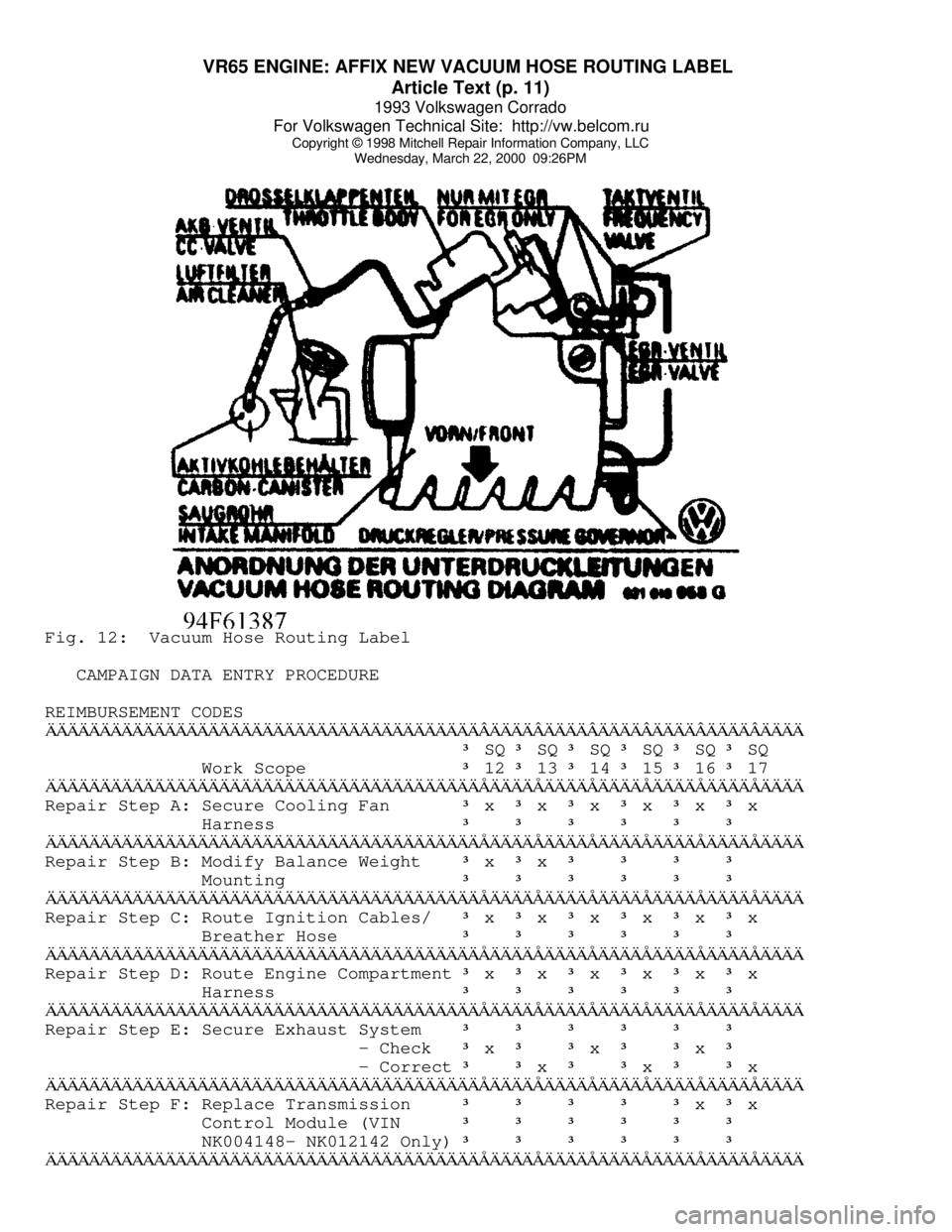
Wednesday, March 22, 2000 09:26PMFig. 12: Vacuum Hose Routing Label
CAMPAIGN DATA ENTRY PROCEDURE
REIMBURSEMENT CODESÄÄÄÄÄÄÄÄÄÄÄÄÄÄÄÄÄÄÄÄÄÄÄÄÄÄÄÄÄÄÄÄÄÄÄÄÄÄÄÄÂÄÄÄÄÂÄÄÄÄÂÄÄÄÄÂÄÄÄÄÂÄÄÄÄÂÄÄÄÄ
³ SQ ³ SQ ³ SQ ³ SQ ³ SQ ³ SQ
Work Scope
³ 12 ³ 13 ³ 14 ³ 15 ³ 16 ³ 17
ÄÄÄÄÄÄÄÄÄÄÄÄÄÄÄÄÄÄÄÄÄÄÄÄÄÄÄÄÄÄÄÄÄÄÄÄÄÄÄÄÅÄÄÄÄÅÄÄÄÄÅÄÄÄÄÅÄÄÄÄÅÄÄÄÄÅÄÄÄÄRepair Step A: Secure Cooling Fan
³ x ³ x ³ x ³ x ³ x ³ x
Harness
³ ³ ³ ³ ³ ³
ÄÄÄÄÄÄÄÄÄÄÄÄÄÄÄÄÄÄÄÄÄÄÄÄÄÄÄÄÄÄÄÄÄÄÄÄÄÄÄÄÅÄÄÄÄÅÄÄÄÄÅÄÄÄÄÅÄÄÄÄÅÄÄÄÄÅÄÄÄÄRepair Step B: Modify Balance Weight
³ x ³ x ³ ³ ³ ³ Mounting
³ ³ ³ ³ ³ ³
ÄÄÄÄÄÄÄÄÄÄÄÄÄÄÄÄÄÄÄÄÄÄÄÄÄÄÄÄÄÄÄÄÄÄÄÄÄÄÄÄÅÄÄÄÄÅÄÄÄÄÅÄÄÄÄÅÄÄÄÄÅÄÄÄÄÅÄÄÄÄRepair Step C: Route Ignition Cables/
³ x ³ x ³ x ³ x ³ x ³ x
Breather Hose
³ ³ ³ ³ ³ ³
ÄÄÄÄÄÄÄÄÄÄÄÄÄÄÄÄÄÄÄÄÄÄÄÄÄÄÄÄÄÄÄÄÄÄÄÄÄÄÄÄÅÄÄÄÄÅÄÄÄÄÅÄÄÄÄÅÄÄÄÄÅÄÄÄÄÅÄÄÄÄRepair Step D: Route Engine Compartment
³ x ³ x ³ x ³ x ³ x ³ x
Harness
³ ³ ³ ³ ³ ³
ÄÄÄÄÄÄÄÄÄÄÄÄÄÄÄÄÄÄÄÄÄÄÄÄÄÄÄÄÄÄÄÄÄÄÄÄÄÄÄÄÅÄÄÄÄÅÄÄÄÄÅÄÄÄÄÅÄÄÄÄÅÄÄÄÄÅÄÄÄÄRepair Step E: Secure Exhaust System
³ ³ ³ ³ ³ ³ - Check
³ x ³ ³ x ³ ³ x ³ - Correct
³ ³ x ³ ³ x ³ ³ x
ÄÄÄÄÄÄÄÄÄÄÄÄÄÄÄÄÄÄÄÄÄÄÄÄÄÄÄÄÄÄÄÄÄÄÄÄÄÄÄÄÅÄÄÄÄÅÄÄÄÄÅÄÄÄÄÅÄÄÄÄÅÄÄÄÄÅÄÄÄÄRepair Step F: Replace Transmission
³ ³ ³ ³ ³ x ³ x
Control Module (VIN
³ ³ ³ ³ ³ ³ NK004148- NK012142 Only)
³ ³ ³ ³ ³ ³
ÄÄÄÄÄÄÄÄÄÄÄÄÄÄÄÄÄÄÄÄÄÄÄÄÄÄÄÄÄÄÄÄÄÄÄÄÄÄÄÄÅÄÄÄÄÅÄÄÄÄÅÄÄÄÄÅÄÄÄÄÅÄÄÄÄÅÄÄÄÄ
Page 866 of 920

WAVEFORMS - INJECTOR PATTERN TUTORIAL
Article Text (p. 7)
1993 Volkswagen Corrado
For Volkswagen Technical Site: http://vw.belcom.ru
Copyright © 1998 Mitchell Repair Information Company, LLC
Wednesday, March 22, 2000 09:26PM
everything together it does not miss anything (though this is also a
severe weakness that we will look at later). If an injector has a
fault where it occasionally skips a pulse, the meter registers it and
the reading changes accordingly.
Let's go back to figuring out dwell/duty readings by using
injector on-time specification. This is not generally practical, but
we will cover it for completeness. You NEED to know three things:
* Injector mS on-time specification.
* Engine RPM when specification is valid.
* How many times the injectors fire per crankshaft revolution.
The first two are self-explanatory. The last one may require
some research into whether it is a bank-fire type that injects every
360ø of crankshaft rotation, a bank-fire that injects every 720ø, or
an SFI that injects every 720
ø. Many manufacturers do not release this
data so you may have to figure it out yourself with a frequency meter.
Here are the four complete steps to convert millisecond on-
time:
1) Determine the injector pulse width and RPM it was obtained
at. Let's say the specification is for one millisecond of on-time at a
hot idle of 600 RPM.
2) Determine injector firing method for the complete 4 stroke
cycle. Let's say this is a 360
ø bank-fired, meaning an injector fires
each and every crankshaft revolution.
3) Determine how many times the injector will fire at the
specified engine speed (600 RPM) in a fixed time period. We will use
100 milliseconds because it is easy to use.
Six hundred crankshaft Revolutions Per Minute (RPM) divided
by 60 seconds equals 10 revolutions per second.
Multiplying 10 times .100 yields one; the crankshaft turns
one time in 100 milliseconds. With exactly one crankshaft rotation in
100 milliseconds, we know that the injector fires exactly one time.
4) Determine the ratio of injector on-time vs. off-time in
the fixed time period, then figure duty cycle and/or dwell. The
injector fires one time for a total of one millisecond in any given
100 millisecond period.
One hundred minus one equals 99. We have a 99% duty cycle. If
we wanted to know the dwell (on 6 cylinder scale), multiple 99% times
.6; this equals 59.4
ø dwell.
Weaknesses of Dwell/Duty Meter
The weaknesses are significant. First, there is no one-to-one
correspondence to actual mS on-time. No manufacturer releases
dwell/duty data, and it is time-consuming to convert the mS on-time
readings. Besides, there can be a large degree of error because the
conversion forces you to assume that the injector(s) are always firing
at the same rate for the same period of time. This can be a dangerous
assumption.
Second, all level of detail is lost in the averaging process.
This is the primary weakness. You cannot see the details you need to
make a confident diagnosis.